ClimaCheck PA Pro III-NX400 Instructions for use

ClimaCheck PA Pro III Hardware Manual –2018-05-15 1
ClimaCheck
PA Pro III – NX400
Hardware user manual
2019-01-29
Updated for Application v. 2.08

ClimaCheck PA Pro III Hardware Manual –2018-05-15 2
Safety Precautions
Read the instruction manuals for all relevant equipment carefully before
starting to use ClimaCheck Performance Analysing systems.
If equipment is used in a way not specified by producer the protection and safety
provided may be impaired.
For activities related to electrical systems, pressurised systems as well as systems charged with
refrigerants certifications/licenses are required in most countries.
ClimaCheck products are only intended for use by competent technicians/engineers with on each
market required certifications/licenses.
Any work with electricity, pressurised systems and refrigerant involve potential dangers to human
health and system integrity if not conducted with caution. In many cases the value of products or
cost of production loss represents great values. ClimaCheck do not assume any responsibility for
injuries or costs occurring if failures are caused in connection with measurements. It is the user that
must evaluate if an installation can be carried out without risks to cause injuries and/or damage.
Installation should only be carried out when it can be done with proper safety margins.
The information in this document is ClimaCheck’s property. The content is strictly confidential and it
is forbidden to distribute information about the contents, other than to personnel at ClimaCheck,
resellers, agents or licence holders without written permission from ClimaCheck Sweden AB. It is
not allowed to copy parts of the documentation, store on data media or other forms, including photo
copies or recording without written permission from ClimaCheck, the copyright owner. First edition
(2009-04-20)
ClimaCheck distributes this document without warranty for the contents. Furthermore,
ClimaCheck reserves the right to make changes, amendments and cut outs in this document
without any further notice. The reason can be printing errors, faulty information, or improvements.
These kinds of changes are always included in new editions of this document.
All rights reserved.
© ClimaCheck Sweden AB

ClimaCheck PA Pro III Hardware Manual –2018-05-15 3
TABLE OF CONTENTS
Safety Precautions .............................................................................................................. 2
1Overview..................................................................................................................... 4
1.1 LED indicators ......................................................................................................... 4
1.2 Display ................................................................................................................... 7
1.3 Climacheck internal application version and PA-ID ....................................................... 8
2Communication ............................................................................................................ 9
2.1 Ports ...................................................................................................................... 9
2.2 SMS Commands ...................................................................................................... 9
3PA Pro III internal application ...................................................................................... 10
3.1 Menu structure ...................................................................................................... 10
3.2 View all values....................................................................................................... 11
3.3 Send interval / Intense send ................................................................................... 11
3.4 Signal level ........................................................................................................... 11
3.5 1-Wire temperature sensors.................................................................................... 12
3.6 Reboot and Reload Configuration ............................................................................. 14
3.7 Reload configuration from Online server ................................................................... 14
3.8 Reboot ................................................................................................................. 14
3.9 Backup configuration to USB memory....................................................................... 14
3.10 Load configuration from USB memory................................................................... 15
3.11 Set network interface ......................................................................................... 15
3.12 Log data to USB memory .................................................................................... 16
4PA Pro III configurator ................................................................................................ 17
4.1 Overview .............................................................................................................. 17
4.2 Password protection ............................................................................................... 18
4.3 Adjust Clock.......................................................................................................... 18
4.4 Configuration files .................................................................................................. 19
4.5 Edit PA Pro III input configuration ............................................................................ 20
4.6 Communication settings ......................................................................................... 24
4.7 Mobile tab............................................................................................................. 24
4.8 LAN 1 tab ............................................................................................................. 25
4.9 WLAN tab ............................................................................................................. 26
4.10 Gateway tab ...................................................................................................... 27
4.11 Debug tab ......................................................................................................... 27
5External switches and connections................................................................................ 28
5.1 Analog Input Mode selection switches (mA/V) ........................................................... 28
5.2 Communication mode selection switch...................................................................... 28
5.3 A and B alarms to digital out ................................................................................... 29
5.4 External connections .............................................................................................. 29
ClimaCheck PA Pro III Hardware Manual –2018-05-15 4
1Overview
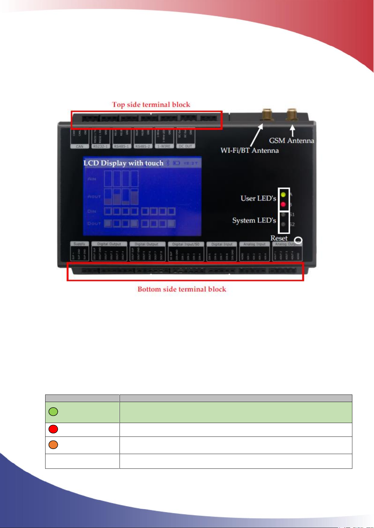
On the front of the PA Pro III unit a display, 4 LEDs and the reset button can be found.
Figure 1 Front view of ClimaCheck PA Pro III NX400
1.1 LED indicators
The ClimaCheck PA Pro III has 4 LED indicators:
-A: ClimaCheck online
-B: 1-wire / Modbus
-S1: Status
-S2: Modem
The A LED indicates the status on contact with ClimaCheck online server.
A LED
Status
900ms On,
900ms Off
(Green)
Connection with Climacheck Online OK (Normal operation)
Fast blinking
(Red)
PA Pro III unsuccessful to send data to Climacheck Online server
(Yellow)
-
Off
No connection e.g. no LAN or Modem connection to Internet
ClimaCheck PA Pro III Hardware Manual –2018-05-15 5
The B LED indicates Modbus and 1 wire communication status
B LED
Status
900ms On,
900ms Off
(Green)
All configured Modbus and 1-Wire units OK and no Alarms active (Normal
operation)
0.400ms On,
0.400ms Off
(Red)
Modbus communication error (see display for additional information)
Continuous On,
Off (Red)
1-Wire communication error (see display for additional information)
On (Red)
Alarms active in the Easycool controller, see alarm page on Climacheck Online
(Yellow)
-
When the Modbus or 1-Wire communication alarm is active, address and name of the unit can be
seen in the display.
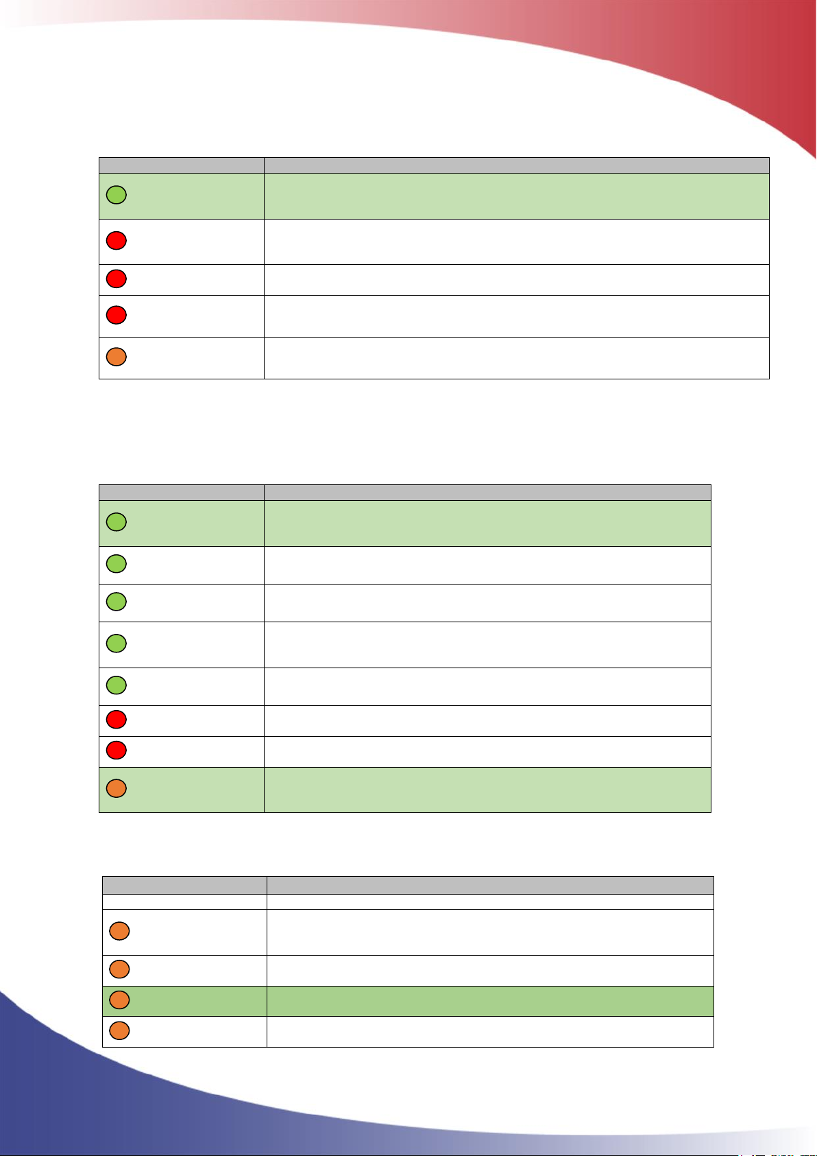
The S1 LED indicates the status on the internal ClimaCheck application.
S1 LED
Status
500ms On,
500ms Off
(Green)
Internal ClimaCheck application running OK (Normal operation)
Fast blinking
(Green)
The unit has been forced into recovery mode with the use of the
system switch. The application is not executing.
Fastest blinking
(Green)
The unit is initializing, preparing to start the application.
1500ms On,
500ms Off
(Green)
The unit is executing the application program, while
charging the internal back-up battery.
75ms On / 925ms
Off (Green)
Execution speed is different from full-speed.
Fast blinking,
(Red)
A runtime error has been detected in the program, contact Climacheck
support
Alternating
Fast/Slow (Red)
The unit has lost its firmware, contact Climacheck support
500ms On /
500ms Off
(Yellow)
Communication with PC Software over USB established (Normal
operation when logging direct to a computer)
The S2 LED indicates the modem status.
Communication status is showed as an icon in the display and with the S2 LED, see table below.
S2 LED
Status
Off
The GSM module is turned off
600 ms On / 600
ms Off (Yellow)
No SIM card inserted or no PIN code entered, or network search in
progress, or ongoing user authentication, or network logon in
progress.
Single 75 ms On
/ 3 s Off (Yellow)
Logged to the network.
No call in progress.
Double 75 ms On
/3 s Off (Yellow)
A GPRS session is active
(bars indicate signal strength)
Flashing (Yellow)
Indicates GPRS data transfer.

ClimaCheck PA Pro III Hardware Manual –2018-05-15 6
ClimaCheck PA Pro III Hardware Manual –2018-05-15 7
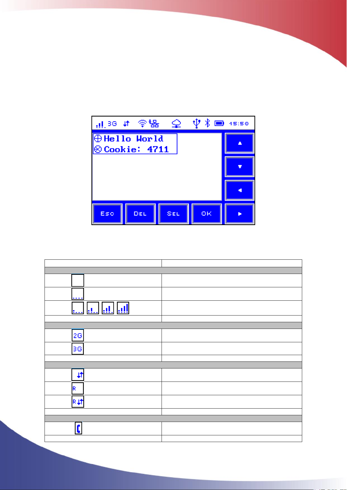
1.2 Display
On the front of the PA Pro III unit a 240x160 pixel, withe on blue, LCD display with built in resistive
touch sensing can be found.
The top part of the display is reserved for a status bar showing status of the different communication
interfaces as well as the time and the battery status, see Figure 2
The main part of the display is reserved for internal Climacheck PA Pro III application showing menus
and data. The lower and right side is used for virtual buttons to navigate.
Figure 2 Display with status bar and
The icons on the status bar are:
Icon
Status
GSM Status
GSM off
GSM on
Signal strength
GSM network type
2G
3G
Mobile network status
Network connected
Roaming
Network connected while roaming
Call Status
Call active (not used in ClimaCheck application)

ClimaCheck PA Pro III Hardware Manual –2018-05-15 8
Wi-Fi Status
Wi-Fi Off
Wi-Fi on
Wi-Fi signal level
LAN Status
LAN off
LAN on (disconnected)
LAN connected
RTCU Gateway Status
RTCU Gateway not enabled
RTCU Gateway enabled
RTCU Gateway connected
USB status
USB host supported
Bluetooth status
Bluetooth off
Bluetooth on
Power status
Battery level (animated while charging)
Table 1
1.3 ClimaCheck internal application version and PA-ID
Each PA Pro III unit has a unique id number to identify it on the ClimaCheck Online server, this
number is set by ClimaCheck and can be seen in the display after the unit has booted up as
“ID=XXXXXX”.
The internal application version can be seen in the display on the same row as the PA-ID. Contact
ClimaCheck support for information on the latest version.

ClimaCheck PA Pro III Hardware Manual –2018-05-15 9
2Communication
2.1 Ports
The PA Pro III unit has LAN, WLAN and Mobile connections to communicate with the ClimaCheck
server. It also has a USB to communicate locally with a computer.
PA Pro III uses the following ports when communicating with the ClimaCheck Online server:
Data sent to ClimaCheck online: UDP outgoing data on port 2049 to URL
online.climacheck.com
Data received from ClimaCheck online: TCP http request outgoing session, port 80, to URL
integration.climacheck.com
Configuration/set-up to PA Pro III from ClimaCheck online: TCP request outgoing session on port
80 to URL integration.climacheck.com
ClimaCheck Gateways to deployment server: TCP, port 5001, to URL online.climacheck.com
Port 2049 to our URL - send UDP text string (ID, Timestamp, data1, data2, ….)
Port 80 to our URL - Send a Http Request for desired analysed values and receive response,
(see Integration manual), also used to check and fetch configuration update
Port 5001 to our URL - used for firmware and application updates and trouble-shooting of
ClimaCheck Gateway through deployment server
2.2 SMS Commands
SMS commands can be sent to PA Pro III to control it. The Modem in the unit is always active and
sms commands are executed regardless of communication mode (GPRS, LAN, WLAN) as long as an
active sim card is inserted.
Table 2, SMS commands
Command
Function
CFG
Fetch configuration from Climacheck Online server
CMD
Check for new commands on Climacheck Online server
RST
Reboot unit
APN new_apn
Changes the APN settings to “new_apn”. If APN internet.com is sent it will
change APN to internet.com
NET GPRS
Changes communication mode to mobile/GPRS
NET LAN
Changes communication mode to LAN
NET WLAN
Changes communication mode to WLAN
There should be One space between the command (APN or NET) and the parameter (new_APN,
LAN, WLAN, GPRS).
The unit will respond with a SMS and then execute the command.
If communication mode is changed with SMS commands the unit will use the pre-set settings for
the selected mode. To change communication settings like APN, SSID´s or IP addresses for GPRS,
LAN or WLAN use the PA Pro III Configurator, see section 4.6.
ClimaCheck PA Pro III Hardware Manual –2018-05-15 10
3PA Pro III internal application
The chapter describes functions in the internal application of the PA Pro III that are accessible
through the display on the unit.
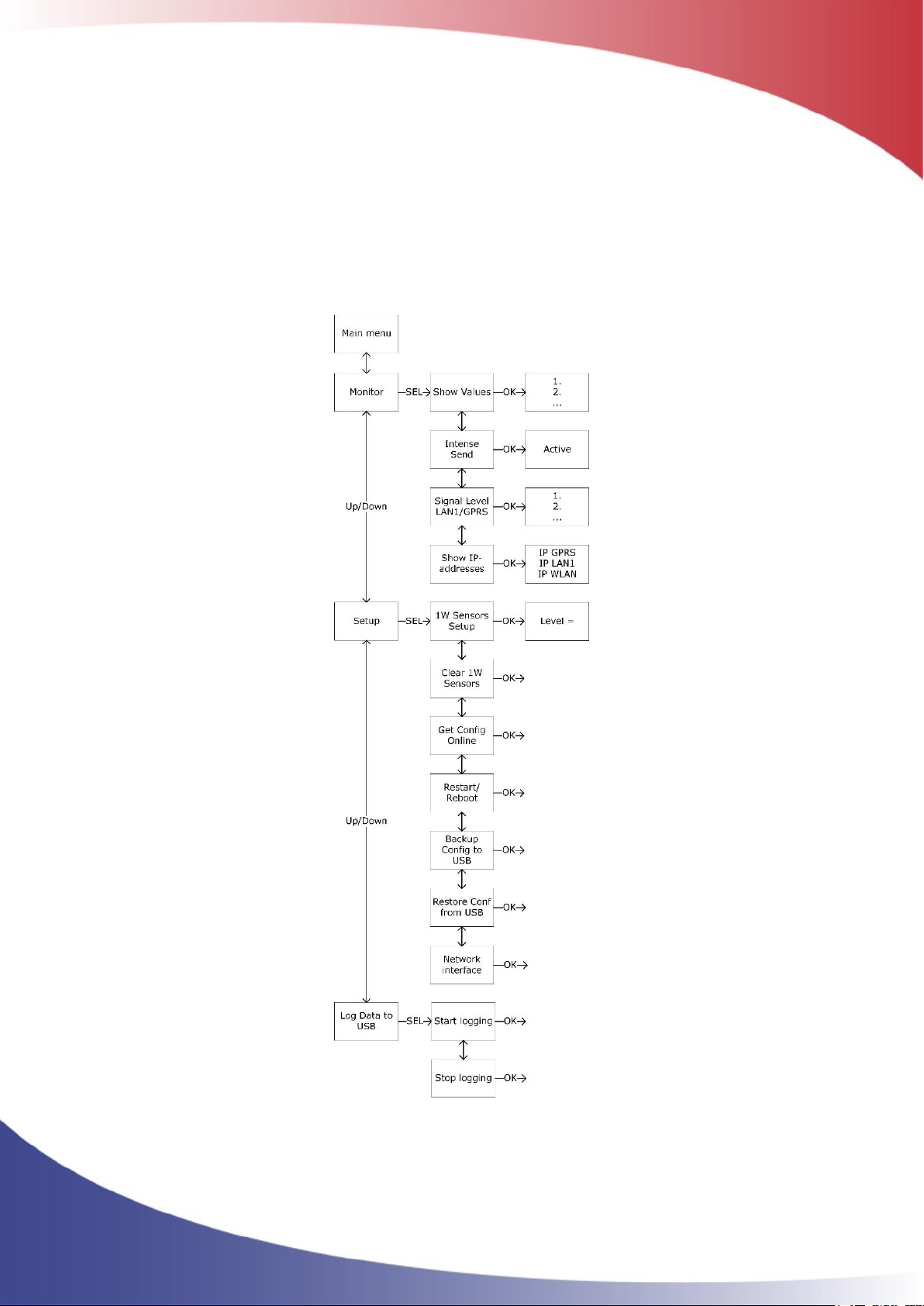
3.1 Menu structure
The menu structure is shown in the figure below. To open a sub menu press the SEL button, to
choose a function or confirm a configuration OK button is used. To go back press ESC.
Figure 3 PA Pro III Menu

ClimaCheck PA Pro III Hardware Manual –2018-05-15 11
3.2 View all values
All values, from internal inputs and external units connected through Modbus, can be seen on the
Show values menu. The list of values varies depending on the number of power meters, IO-modules
and other external units that are configured.
To view all values
-Press ESC to enter the Main menu
-Press Down until “Monitor” is showed in the display
-Press SEL to enter Monitor menu
-“Show values” appears in the display
-Press OK
Values are showed with one sensor/value on each row with Comment/Description, sensor reading,
unit and Modbus address for external units. Press Up/Down to step through the list of values.
3.3 Send interval / Intense send
Data is sent to the Climacheck server ones every minute when the compressor is on and every 5
minute when the compressor is off. To activate “intense send” and send data every 15 second
-Press ESC to enter the Main menu
-Press Down until “Monitor” is showed in the display
-Press SEL to enter Monitor menu
-Press down until “Intense send” is showed in the display
-Press OK
-“Intense Send Active” appears
Intense send is automatically swished off after 15 minutes.
3.4 Signal level
GPRS/WLAN signal strength can be seen in the display of the unit as bars ,see section 1.2. To view
the value in % or dBm
-Press ESC to enter the Main menu
-Press Down until “Monitor” is showed in the display
-Press SEL to enter Monitor menu
-Press Down until “Signal level GPRS” or “Signal level WLAN” is showed in the display
-Press OK
Signal strength is presented in dBm and %. For reliable data transmission a signal strength above 2
“bars”, -80dBm or 40% is required.
3.5 Show IP-addresses
To show what IP-addresses the PA Pro III unit uses on LAN, WLAN and GPRS connections
-Press ESC to enter the Main menu
-Press Down until “Monitor” is showed in the display
-Press SEL to enter Monitor menu
-Press Down until “Show IP-addresses” I showed in the display
-Press OK
IP-addresses for all network interfaces is presented. To change communication settings see section
3.12
ClimaCheck PA Pro III Hardware Manual –2018-05-15 12
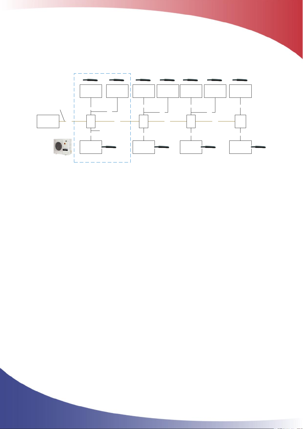
3.6 1-Wire temperature sensors
A 1-Wire temperature sensor is a bus sensor and unlike Pt1000 sensors the measured value of the
sensor is not affected by the resistance in the cable between the master (PA Pro III) and the slave
(sensor). Limitations in number of sensors and cable length as well as the preferred topology is
described below.
ClimaCheck
1-wire master
concom
PA Pro III
Split
(+0.5m)
Split
(+0.5m)
< X m
1-wire sensor
(+0.5 m)
1-wire sensor
(+0.5 m)
1-wire sensor
(+0.5 m)
< 3 m
<3 m
< 3 m
< X m
1-wire sensor
(+0.5 m)
1-wire sensor
(+0.5 m)
< 3 m
< 3 m
Split
(+0.5m)
1-wire sensor
(+0.5 m)
1-wire sensor
(+0.5 m)
1-wire sensor
(+0.5 m)
< 3 m
<3 m
< 3 m
< X m Split
(+0.5m)
1-wire sensor
(+0.5 m)
1-wire sensor
(+0.5 m)
1-wire sensor
(+0.5 m)
< 3 m
<3 m
< 3 m
< X m
1-wire bus
Stub
i.e. cold room,
Heating system,
chilled water
i.e. missing unit
temperatures
Figure 4 1-Wire preferred topology
The preferred topology, Figure 4, is with the PA Pro III connected at one end of the 1-Wire bus and
each sensor connected to the bus with branches or “stubs” where each stub is less than 3m. The PA
Pro III can handle a total of 16 sensors and a total “weight” of 65 m. The weight is the length of all
cables + 0.5m per sensor + 0.5m per split.
Weight = total cable length + 0.5*sensor + 0.5*split
Example: 3 sensors on 2 meter stubs that is located 5 meters from the PA Pro III with 1 split has a
total weight of 0.5*3+(2*3+5)+0.5*1=14.
Do not run signal wires in parallel with power cables.
3.6.1 1-Wire temperature sensor setup
1-Wire sensors delivered with the system/logger will be configured and marked at shipment. Sensors
added later have to be configured/connected.
The 1-Wire sensor has a unique ID to identify it on the 1-Wire bus and each sensor needs to be
configured/connected in the PA Pro III. When a sensor has been connected to a specific position it
will stay on this position regardless of where on the bus it is connected or which 3.5 mm 1-wire
socket that is used.
3.6.2 Connecting sensors
The sensors need to be connected and configured one at a time. Use the following sequence to
setup and connect the sensors:
-Connect sensor
After a few seconds “Unknown 1-W sens found” is displayed
-Press ESC to enter the Main menu
-Press Down until “Setup”is showed in the display
-Press SEL to enter setup menu
-“1W Sensor Setup”appears in the display
-Press OK to start setup

ClimaCheck PA Pro III Hardware Manual –2018-05-15 13
If this is the first setup ”T1 Sensor not conf” appears in the display, if sensors are already
configured these will be listed.
-With the up and down arrows go to the position you want to save a sensor to
-Press SEL
-“TX New=xxxxxx OK” is showed in the display (Were TX is the position and xxxxxx is the id
number of the sensor)
-Confirm with OK, “S-RID Saved” appears for 2 seconds
-Temperature reading and ID is appearing in the display “TX=XX.X ID=xxxxxx”
-Press ESC 4 times to go back to the main menu or start from the top to connect another
sensor.
If “No new s-r found” appears while setting up a new sensor the PA Pro III cannot find any sensor
on the bus that is not already configured, check connection and make sure the sensor has not been
connected already.
3.6.3 Replace a 1-Wire sensor
To replace a sensor
-first disconnect old sensor
-Press ESC to enter the Main menu
-Press Down until “Setup” is showed in the display
-Press SEL to enter setup menu
-“1W Sensor Setup”appears in the display
-Press OK
-select the sensor number in the list, it will say “Sensor missing”.
-Connect new sensor and press SEL,
-“Tx NEW=xxxxxx OK” is showed in the display
-Confirm with OK, “S-RID Saved” appears for 2 seconds
-Temperature reading and ID is appearing in the display “TX=XX.X ID=xxxxxx”
-Press ESC 4 times to go back to the main menu.
3.6.4 Clear all 1-Wire sensors
To clear all configured 1-Wire sensors
-Press ESC to enter the Main menu
-Press Down until “Setup” is showed in the display
-Press SEL to enter setup menu
-Press down until “Clear 1W Sensors” is showed in the display
-Press OK
-“Clearing..” appears and then your back in the setup menu
This will clear all sensor including preconfigured sensors. You can now connect the sensors again,
see section 3.6.2.
3.6.5 Trouble shoot 1-Wire sensors
-“No tempsensors or conn. Wrong. OK?” is showed while configuring sensors.
Check wiring and make sure all sensors are connected properly (Data, GND). If the wires
from one (1) sensor is mixed up the whole 1-Wire bus stops.
-“No new s-r found” is showed when trying to connect/configure sensor.

ClimaCheck PA Pro III Hardware Manual –2018-05-15 14
Check wiring and make sure sensor is not already connected/configured on a different
position.
-Sensors has been connected/configured on the wrong position
Clear all configured sensors and connect them again, see section 3.6.4
-A configured 1-Wire sensor is showing -999.00
PA Pro III has lost connection with the sensor, check wiring.
3.7 Reboot and Reload Configuration
Most of the configuration for external units can be done on the Climacheck server. Any changes to
Modbus addresses for external units such as energy meters or IO modules can be done on the
Climacheck Online server and then downloaded to the unit. If the unit has an internet connection it
will try to contact the server every 6 hour to check for commands to Reload configuration from the
server or Restart.
The unit can also be restarted or forced to reload configuration from the Setup menu.
3.8 Reload configuration from Online server
Make sure the unit has internet connection and then
-Press ESC to enter the Main menu
-Press Down until “Setup” is showed in the display
-Press SEL to enter setup menu
-Press Down until “Get Config Online” is showed in the display
-Press OK to load configuration from CC Online server
-“Waite for config, Loading..” appears in the display
After a few seconds, when the configuration has been updated, the unit will go back to the initial
view.
All configuration made locally with the PA Pro Configurator, section 4, will be overwritten with the
configuration from the server.
3.9 Reboot
-Press ESC to enter the Main menu
-Press Down until “Setup” is showed in the display
-Press SEL to enter setup menu
-Press Down until “Restart/Reboot” is showed in the display
-Press OK
The unit will reboot.
3.10 Backup configuration to USB memory
The present configuration in the unit can be saved to a USB memory connected to the USB-port on
the top side of the unit, see Figure 20.
To save the configuration follow the steps below
-Shut off logger by disconnecting power
-Connect the USB memory to the USB-A port on top side of the unit.
-Start logger by connecting power again
Waite for the unit to start and then

ClimaCheck PA Pro III Hardware Manual –2018-05-15 15
-Press ESC to enter the Main menu
-Press down until “Setup” is showed in the display
-Press SEL to enter Setup menu
-Press down until “Backup Config to USB” is showed in the display
-Press OK, “Saving to USB” is showed in the display
-Press ESC to go back to the main menu
A *.cfg file is created with the PA-id as name.
3.11 Load configuration from USB memory
To load a configuration from a *.cfg configuration file on a USB memory follow the steps below
-Shut off logger by disconnecting power
-Connect the USB memory to the USB-A port on top side of the unit.
-Start logger by connecting power again
Waite for the unit to start and then
-Press ESC to enter the Main menu
-Press down until “Setup” is showed in the display
-Press SEL to enter Setup menu
-Press down until “Restore Conf from USB” is showed in the display
-Press OK, “Loading from USB” is showed in the display
-Press ESC to go back to the main menu
3.12 Set network interface
Network interface used by the PA Pro to communicate with internet can be set on the Set network
interface menu. To enter it
-Press ESC to enter the Main menu
-Press down until “Setup” is showed in the display
-Press SEL to enter Setup menu
-Press down until “Network Interface” is showed in the display
-Press OK
The PA Pro will change view, at the top of the page the current selection is displayed as (Active
XXXX) where XXXX is GPRS, LAN, WLAN, non or DIP. Below 6 options are listed:
Network
Description
GPRS
Use the built-in modem
LAN
Use the LAN connection to connect trough a local network
LAN2 (Not
present)
Not present
WLAN
Use the WLAN/Wi-Fi connection.
No network
Unit is not connected to internet. Only USB connection to a local computer is
used.
Use DIP-Switch
Changes network dependant on the DIP-switch setting, see section 5.2
-Choose network interface by pressing directly on the desired interface.
-Press OK to confirm
To change communication settings like APN, SSID´s or IP addresses for GPRS, LAN or WLAN use

ClimaCheck PA Pro III Hardware Manual –2018-05-15 16
the PA Pro III Configurator, see section 4.7 , 4.8 or 4.9.
3.13 Log data to USB memory
Data can be saved to a USB memory connected to the USB-port on the top side of the unit, see
Figure 20. Data is saved with the same interval that is used to send data to the ClimaCheck Online
server i.e. ones every minute when the compressor is running and every 5 minute when it´s off.
The USB memory needs to be formatted with the file system FAT or FAT32.
To activate follow the steps below.
-Shut off logger by disconnecting power
-Connect the USB memory to the USB-A port on top side of the unit.
-Start logger by connecting power again
Wait for the unit to start and then
-Press ESC to enter the Main menu
-Press down until “Logg data to USB” is showed in the display
-Press SEL to enter USB menu, “Start logging” is showed in the display
-Press OK
A folder is created on the USB memory with the PA-id as name and the data is saved in *.LOG files
as comma separated values. A new file is created for each day and when the USB memory is full
the logging stop.
For instructions on how to run *.LOG files in the Climacheck software please see the ClimaCheck
Software manual.
Figure 5 USB memory with data from two different PA Pro III
To deactivate follow the steps below.
-Press ESC to enter the Main menu
-Press down until “Logg data to USB” is showed in the display
-Press SEL to enter USB menu
-Press down to “Stop logging” is showed in the display
-Press OK

ClimaCheck PA Pro III Hardware Manual –2018-05-15 17
4PA Pro III configurator
The chapter describes how to use the PA Pro III configurator for inputs, external units and
communication settings. The PA Pro III Configuration tool can be found under the Perfomance
Analyser Pro menu in the ClimaCheck software.
Figure 6
All Climacheck PA Pro III systems have their default configuration on the Climacheck Online server
but with the configurator, settings can be changed offline without the need of an internet
connection.
To exit the configurator go to File menu and then Exit. The configurator will be stopped and the
Climacheck software is opened again.
4.1 Overview
The Action menu contains functions for connecting, reboot and disconnecting from the device,
adjust the internal clock, get and send configuration and to unlock the configurator to be able to
change configuration. With the view menu Debug messages can be displayed.
The configurator has 6 tabs
Figure 7, PA Pro III Configurator
IO Config Edit
Handles configuration for analog inputs on the PA Pro III and external units connected through
Modbus/RS485. Data send interval, interval to fetch commands from the ClimaCheck Online server
and Debug mode is also controlled from this tab.

ClimaCheck PA Pro III Hardware Manual –2018-05-15 18
Mobile
APN, username and other settings for the built-in modem
LAN1
IP address and other settings for the wired/ethernet network connection.
WLAN
SSID, passphrase and other settings for the wireless LAN (Wi-Fi) connection
Gateway
Settings for the Climacheck RTCU Gateway
Debug
View debug information
Functions on the different tabs are described in more detail in the below sections.
4.2 Password protection
To be able to write a configuration to the PA Pro III from the configurator a password needs to be
entered. All units are configured with a default password but this can easily be changed.
4.2.1 Unlock unit
Follow the steps below to unlock the unite.
-On the Action menu go to Unlock for Write to Device
-Enter the password in the new window and press OK (default password: ef56 )
When the correct password has been entered all menu options are accessible and a new option
appears on the Action menu where the user password can be changed.
4.2.2 Change password
To change password follow the steps below
-Unlock the device with present password, see 4.2.1
-On the Action menu go to Configure Password for unlock
-Enter the new password in the window and press OK
The new password is saved.
4.3 Adjust Clock
The internal clock in the unit can be set from the Action menu.
-On the Action menu go to Adjust Clock
-A new window will appear where date and time can be set manually or by Applying the
time from the PC.
-Press Apply to save changes in the device.
Figure 8, Clock settings in Configurator

ClimaCheck PA Pro III Hardware Manual –2018-05-15 19
Note that the clock is also set from the ClimaCheck Online server when the unit is connected to
internet.
4.4 Configuration files
All configuration can be saved to and loaded from configuration files, *.CFG.
4.4.1 Open PA Pro III configuration
To open the present configuration follow the steps below
-In the Climacheck software Go to PAPro III menu and PA Pro III Configuration
-On the Action menu choose Connect to Device, in the lower right corner the PAID of the
connected device can be seen, Figure 7.
-On the IO Config Edit tab go to Edit Device and then Open Configuration in device
The configuration is loaded and all settings are displayed on the IO Config Edit tab.
4.4.2 Open and make a backup of the PA Pro III configuration
To open the present configuration and save it to a file follow the steps below
-Go to PAPro III menu and PA Pro III Configuration
-On the Action menu choose Connect to Device, in the lower right corner the PAID of the
connected device can be seen, Figure 7.
-On the IO Config Edit tab go to Edit Device and then Open Configuration in device
The configuration is loaded and all settings are displayed on the IO Config Edit tab.
-Go to Edit File and Save File, choose a name and press save.
To use your backup and restore settings see section 4.4.3
4.4.3 Load configuration from file to PA Pro III
Follow the steps below to load a configuration from a premade configuration file (*.CFG) to the PA
Pro III. In the Climacheck Software
-Go to PAPro III menu and PA Pro III Configuration
-On the Action menu choose Connect to Device, in the lower right corner the PAID of the
connected device can be seen, Figure 7.
-Unlock the configurator with the user password, see section 4.2
-On the IO Config Edit tab go to Edit File and then Open File
-Select the Configuration file in the new window and press Open.
The file is loaded and all settings are displayed on the IO Config Edit tab.
-Go to Edit Device menu and then Save configuration in device
All configuration in the PA Pro III will be replaced by the new configuration file. To make a backup
of existing configuration see section 4.4.1

ClimaCheck PA Pro III Hardware Manual –2018-05-15 20
4.5 Edit PA Pro III input configuration
Figure 9 IO Config Edit tab with 4 external units
4.5.1 Change Analog input configuration
The analog inputs on the PA Pro III unit and Domat R560 module can be used for different 0-10V
and 4-20mA sensors.
To change configuration, follow the steps below.
-Go to PAPro III menu and PA Pro III Configuration
-On the Action menu choose Connect to Device, in the lower right corner the PAID of the
connected device can be seen, Figure 7.
-Unlock the configurator with the user password, see section 4.2
-On the IO Config Edit tab go to Edit Device and then Open Configuration in device
The configuration is loaded and all settings are displayed on the IO Config Edit tab.
-Open the list with inputs for a device with the + to the left, see Figure 10
-Select new sensor type on the drop-down menu
-Write a Comment for the new sensor, this name is what will be showed in the Data source.
-On the IO Config Edit tab go to Edit Device and then Save Configuration in device, the unit
will reboot.
Note that the Sensor Type list is common for PA Pro III and R560 but the analog inputs on the PA
Pro III can’t handle Pt 1000 sensors.
Figure 10
Table of contents
Other ClimaCheck Measuring Instrument manuals

Popular Measuring Instrument manuals by other brands

EUTECH INSTRUMENTS
EUTECH INSTRUMENTS STANDARD PHSCAN 1 PH TESTER Caractéristiques

MICRO-EPSILON
MICRO-EPSILON surfaceCONTROL 3D SC3200 Assembly instructions

Minebea
Minebea CSD-892B-07-25 instruction manual

PCB Piezotronics
PCB Piezotronics IMI SENSORS TOM607A11 Installation and operating manual

Thermo Scientific
Thermo Scientific Sarasota 200 user guide

Alpha Omega Instruments
Alpha Omega Instruments 9510 Series instruction manual


