cliMATE AAS 800 User manual

SAVE THESE INSTRUCTIONS FOR FUTURE REFERENCE
OWNER’S MANUAL
AIR SCRUBBER
MODEL: AAS 800

OWNER’S MANUAL AAS800 AIR SCRUBBER
Page 2
READ AND SAVE THESE INSTRUCTIONS
The Air Scrubber is the most compact, portable unit in our popular line of high performance airscrubbers. The Air
Scrubber features a 22” x 24” footprint and stands only 14” tall. Weighing less than 35 lbs and featuring a molded
handle and stackable design, the Air Scrubber is easy to carry, transport, and store.
For maximum exibility, the Air Scrubber features variable airow and can be operated vertically or horizontally.
The Air Scrubber is designed to accept 16" inlet ex duct and 10" lay at outlet duct for a variety of operating set-up
options.
The Air Scrubber delivers a maximum 500 CFM of HEPA ltered air, while drawing less than two amps of power.
This makes the Air Scrubber perfect for a variety of remediation projects where space and power are at a premium.
A single Air Scrubber is capable of providing 4 air changes per hour (the recommended minimum) on a 7500 cubic
foot room (more than a 30' x 30'x 8').
The Air Scrubber's 2-stage lter design - with documented true HEPA ltration performance - will remove hazardous
particles from the air and, with the addition of an optional carbon/potassium permanganate lter, will adsorb a wide
range of odors and gases.
The Air Scrubber
• Less than 2 amps
• Compact design
• Variable speed ow
• Multiple ducting options
• Tough, plastic cabinet
• Optional carbon lter

OWNER’S MANUAL AAS800 AIR SCRUBBER
Page 3
SPECIFICATIONS
Part No. AAS800
Power 240 V, 0.7 A, 170 W
Blower 500 CFM
Filters: 1st stage 1"Pleated Media, 18" x 18" (optional) 1" Carbon and Potassium Permanganate 2nd stage 2.5"
Pleated HEPA 18" x 18"
Warranty One Year, 100% Parts and Labor
Dimensions Width 22"
Height 14"
Depth 24"
Weight 33 lbs.
IMPORTANT SAFETY INSTRUCTIONS
CAUTION
CAUTION: Risk of electric shock. Can cause injury or death. To reduce the risk of electric shock:
• Do not expose to standing water or rain
• Connect to GFCI outlet
• Do not use an extension cord
• Unplug fan before servicing or changing lters.
• Do not block air intake or outlet. One foot minimum distance to obstructions.
Indoor use only
• Do not use as stool or bench
• Do not operate with damaged cord or plug.
• Do not run cord under carpeting.
• Do not cover cord with throw rugs, runners, or similar coverings.
• Do not route cord under furniture or appliances. Arrange cord away from trac area and where it will not be
tripped over.”

OWNER’S MANUAL AAS800 AIR SCRUBBER
Page 4
OPERATION
Transporting the Air Scrubber
The Air Scrubber should be transported vertically or horizontally on the appropriate feet located on the bottom of the
unit or opposite the handle
Electrical Requirements
The Air Scrubber can be plugged into a grounded 15 Amp circuit. It draws about 2 Amps with clean lters and no
ducting. The amp draw will decrease slightly with added ducting and as the lters load with particulate. Due to the
presence of GFCI receptacle, the Pro model must be plugged directly into a wall outlet. No extension cords should
be used.
Air Ducting
A. Inlet Ducting
Occasionally the area to be ltered is dicult to access and/ or the unit cannot be located in the area. In such
cases, the air can be ducted to the unit’s inlet. A round 16” diameter exible duct can be attached to the unit inlet.
It connects by placing the wire in the duct over the duct collar lip at one location and working over it over the lip
gradually. It may be removed after use for easier transport and storage. Flexible 16” duct is available from.
B. Outlet Ducting
A detachable trapazoid shaped exhaust ring is supplied that will allow 10” round lay-at plastic duct to be attached
to the Air Scrubber outlet. Lay-at plastic ducting is available from. To attach ducting to the collar, remove the
ring from the unit by pressing release tab at the top of the grill. Put the plastic duct end through the inside of the
ring. Roll the duct end outward so that it over-laps the outside of the ring. Clip the ring back onto the exhaust grill.
C. Negative Air Ducting
The Air Scrubber can be used to lter and exhaust air from a space. When exhausting to outside the space, the
space will be under a slight negative pressure. This will help prevent airborne particles from leaving the space,
because the negative pressure will draw air in through openings in the space’s exterior surfaces.

OWNER’S MANUAL AAS800 AIR SCRUBBER
Page 5
OPERATION
CAUTION
CAUTION: Exhausting too much air from a space with open combustion devices (e.g. furnace, replace or
water heater) can cause those devices to backdraft. This can contaminate the space with potentially fatal
gases.
In such cases, the Air Scrubber must be used in one of the following three ways:
A. As a ltering unit only. Exhausting no air from the space and thus causing no negative pressure or backdrafting.
B. Exhausting a very limited amount of air which does not cause backdrafting. In case B, the open combustion
devices must be thoroughly checked to guarantee that they do not backdraft while the Air Scrubber is running.
C. Direct the outlet duct from the Air Scrubber to the room with the open combustion device(s). This will positively
pressurize the room with HEPA ltered air, thus preventing backdrafting. As in case B, those combustion devices
must be checked after the Air Scrubber is running to guarantee that they are not backdrafting.
Power/Speed Control
The power/speed switch is located on the control panel. When turned on to any speed, it powers the impeller fan.
Occasionally the impeller fan may not start on low speed. If this occurs, rotate the speed control to high speed until
the impeller fan starts, then adjust it to a lower speed.
CAUTION
CAUTION: Do not remove HEPA lter with the unit on. Removing the top and lters while running will expose
the dangerous rotating impeller fan. Disconnect the appliance before changing lters.

OWNER’S MANUAL AAS800 AIR SCRUBBER
Page 6
OPERATION
Resettable Circuit Breaker
The 12 AMP thermal response resettable circuit breaker protects the unit and devices connected to its duplex GFCI
outlet. The circuit breaker is designed to sense the total current draw through the circuit.
The circuit breaker "trips" when more than 12 amps of electrical current are drawn through the device's power
cord. Should an over-current condition occur, the Air Scrubber on-board circuit breaker prevents nuisance visits to a
remote power junction box.
IMPORTANT
IMPORTANT: Total amperage of the GuardianR plus all devices plugged into the receptacle must not exceed
12 amps. The circuit breaker will not allow for loads in excess of 12 amps, although there is a time delay
before the overloaded circuit is broken.
IMPORTANT
IMPORTANT: When the GuardianR is plugged into a standard "powered" wall outlet the GuardianR's duplex
outlet is electrically "HOT" and AC voltage is present.
GFCI Protection and the On-Board Duplex VAC Outlet
The standard AC voltage outlet GFCI (Ground Fault Circuit Interrupter) protection promotes operator safety in wet
applications. GFCI devices trip when a fault to electrical "ground" is sensed.
It is recommended to check the GFCI protection prior to operation. To check, push the "TEST" button located on
the GFCI duplex outlet. If operating properly the "RESET" button on the GFCI outlet will pop out. A tripped GFCI
is indicated by a small LED. The device can only be "RESET" when the Air Scrubber is connected to a wall outlet
providing standard voltage. This duplex AC outlet allows the inter-connection of other AC powered devices. The sum
total amperage of all devices plugged into the receptacle must not exceed 10 amps.
Servicing
Before each use inspect for damage, blocked inlet or outlet.
Inspect the GFCI to ensure it is not in a "tripped" condition. Push "RESET" to reset the GFCI. When the Air Scrubber
is rst turned on, check for excessive vibration. If the unit vibrates excessively or if impeller rubs on housing, turn o
the unit immediately. Have a service technician inspect the unit to locate the problem.

OWNER’S MANUAL AAS800 AIR SCRUBBER
Page 7
MAINTENANCE
WARNING
Use extreme caution when changing the HEPA lter as hazardous material could be trapped in the media.
Always make sure to dispose of lters in the appropriate way. If you are unsure of how to safely dispose of
any lter-consult an industrial hygienist to ensure that all hazardous materials are contained and disposed
of properly.
Air Filters
The standard Air Scrubber HEPA System is equipped with two lters that progressively lter out smaller particles. An
optional activated carbon/potassium permanganate lter can be also added. These lters must be checked regularly.
Operating the unit with dirty lters will reduce the airow, but will do no harm to the unit. The unit can be run indenitely
with dirty lters. The two standard lters used are listed below (as installed in the unit from top to bottom):
A. 25 to 30% ecient (per ASHRAE 52.1-1992), MERV-7, pleated fabric pre-lter.
B. 99.97% DOP ecient HEPA lter.
Filter replacement
When the amber “lter change light” illuminates. It may be time to replace one or both lters.
To check airow accurately, an airow meter or anemometer must be used:
When the lter change light illuminates; remove all ducting and run on high speed. if the lter light remains lit;
replace the pre-lter and run on high again. If the light remains; it is time to replace the HEPA lter for full 500 CFM
performance.
Airow on high speed with all lters clean and no ducting is slightly over 500 CFM. The unit can be run with very dirty
lters and virtually no ow without harming the unit. The operator’s decision to change lters should be based on lter
cost vs. the unit’s ltering eectiveness. If airow is 250 CFM vs. 500 CFM, the unit will lter particles from a space at
half the rate. The operator must judge if that is acceptable. If the operator determines the lters should be changed
due to low airow, it is most economical to change them in the following order:
Change the pre-lter (top) rst. This is the least expensive lter. Recheck the airow. If the airow is acceptable, no
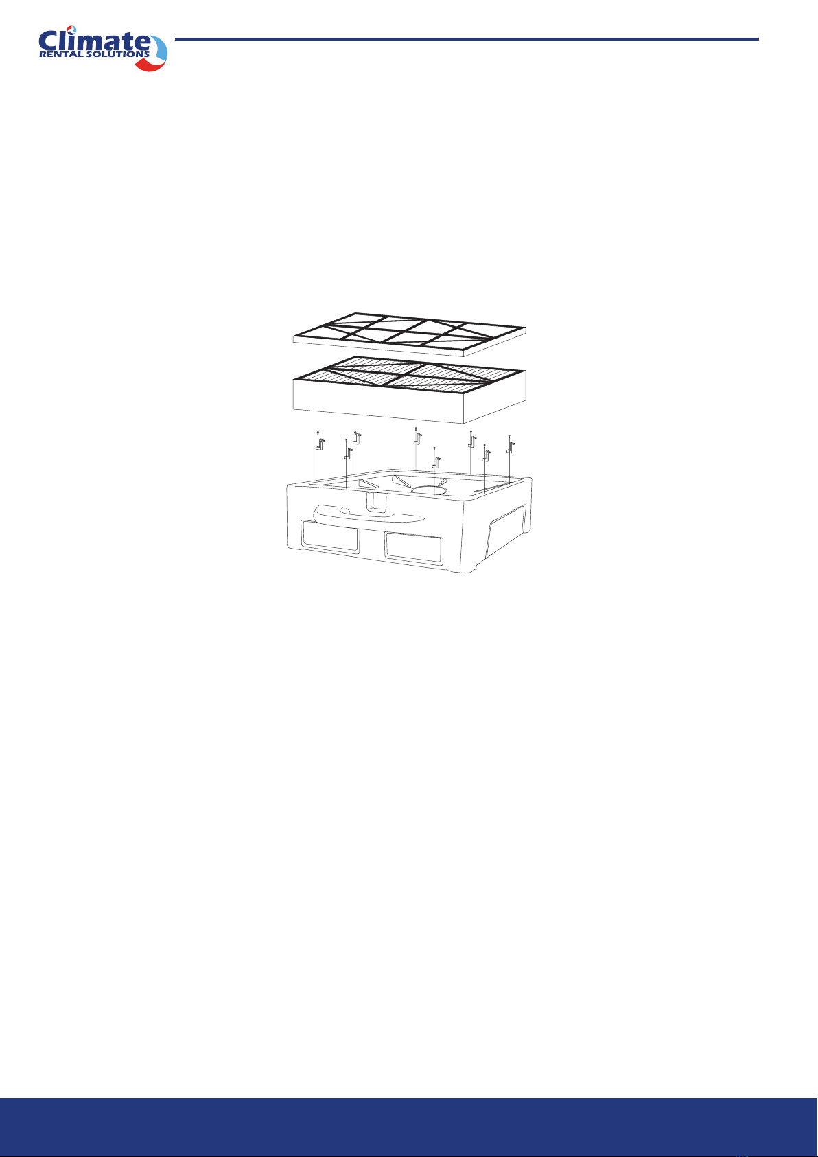
other lters need to be changed. If the airow is still too low, the HEPA lter must be changed. To remove the HEPA
lter, follow these steps:
1. Loosen the eight screws one revolution
2. Rotate all eight clips out of the way.
3. Remove old lter.
4. Installing the new lter is the reverse of these instructions
OWNER’S MANUAL AAS800 AIR SCRUBBER
Page 8
MAINTENANCE
Optional Activated Carbon/Potassium Permanganate Filters They use a blend of activated carbon and
potassium permanganate.
This blend removes the vast majority of gaseous contaminants encountered in most ltering applications. The
activated carbon removes the heavier volatile organics while the potassium permanganate removes lower molecular
weight contaminants. This is well suited to the smoke odors present after re damage.
The life of the media blend depends upon both the hours used and the contamination level. Another advantage of the
blended media versus activated carbon only is that part of the blend changes color as it loads up with contaminants.
It starts out black, then turns pink, then brown, and nally white. It is best changed when it passes the brown stage
and begins to turn white. It has lost most of its eectiveness at that point. The lter is the same size as the pleated
fabric lter. Install it in place of the pleated fabric lter.
WARRANTY
This appliance is not intended for use by persons (including children) with reduced physical,sensory or mental
capabilities, or lack of experience and knowledge, unless they have been given supervision or instruction concerning
use of the appliance by a person responsible for their safety.Children should be supervised to ensure that they do
not play with the appliance.

OWNER’S MANUAL AAS800 AIR SCRUBBER
Page 9
ITEM No DESCRIPTION QTY ITEM No DESCRIPTION QTY
1Screw 46 13 Strain relief-lq tight 1
2Rubber foot 12 14 Power cord 1
3Removable Foam Cap 115 Nut, hex 1
4Upper half shell 1 16 Circuit breaker 1
5Buckle 2 17 Filter net plug alarm lamp 1
6Primary eciency lter 118 AC motor 1
7High eciency lter 119 Fan blade 1
8Fixed buckle 820 Fixed plate 1
9Lower half shell 121 Bottom cover plate 1
10 larger & Wider air outlet 1
11 Switch panel/GFCI panel 1
12 On/o rocker switch, blk 1

CONTACT DETAILS
Climate Rental Solutions Pty Ltd
PO Box 84 Berwick Victoria 3806
Ph:1300 447 247
Email: [email protected]
www.climaterentals.com.au
Table of contents
Other cliMATE Scrubber manuals


