Central Pneumatic 46149 Installation manual

OIL EXTRACTOR
6 1/4 GALLON
46149
SET UP AND OPERATING INSTRUCTIONS
Distributed exclusively by Harbor Freight Tools®.
3491 Mission Oaks Blvd., Camarillo, CA 93011
Visit our website at: http://www.harborfreight.com
Read this material before using this product.
Failure to do so can result in serious injury.
SAVE THIS MANUAL.
Copyright©2001 by Harbor Freight Tools®. All rights reserved. No portion of this manual or any artwork
contained herein may be reproduced in any shape or form without the express written consent of
Harbor Freight Tools. Diagrams within this manual may not be drawn proportionally. Due to continuing
improvements, actual product may differ slightly from the product described herein. Tools required for
assembly and service may not be included.
For technical questions or replacement parts, please call 1-800-444-3353.
Cover Revised 09h

Page 2 For technical questions, please call 1-800-444-3353. SKU 46149
SAVE THIS MANUAL
Keep this manual for the safety
warnings and precautions, assembly,
operating, inspection, maintenance and
cleaning procedures. Write the product’s
serial number in the back of the manual
near the assembly diagram (or month
and year of purchase if product has no
number). Keep this manual and the
receipt in a safe and dry place for future
reference.
Safety Alert Symbol and Signal
Words
In this manual, on the labeling,
and all other information
provided with this product:
This is the safety alert
symbol. It is used to alert
you to potential personal
injury hazards. Obey all
safety messages that
follow this symbol to avoid
possible injury or death.
DANGER indicates
a hazardous
situation which, if not
avoided, will result in death or
serious injury.
WARNING
indicates a
hazardous situation which, if
not avoided, could result in
death or serious injury.
CAUTION, used
with the safety
alert symbol, indicates a
hazardous situation which, if
not avoided, could result in
minor or moderate injury.
NOTICE is used to
address practices
not related to personal injury.
CAUTION, without
the safety alert
symbol, is used to address
practices not related to
personal injury.
SAFETY WARNINGS AND
PRECAUTIONS
KEEP PRODUCT USAGE AREA1. CLEAN. Cluttered areas invite
injuries.
KEEP CHILDREN AWAY FROM2. PRODUCT USAGE AREA. Do not
allow children to handle this product.
STORE IDLE EQUIPMENT.3. When
not in use, tools and equipment
should be stored in a dry location to
inhibit rust. Always lock up tools and
equipment and keep out of reach of
children.
DO NOT USE THIS PRODUCT4. IF UNDER THE INFLUENCE OF
ALCOHOL OR DRUGS. Read
warning labels on prescriptions
to determine if your judgement or
reexes are impaired while taking
drugs. If there is any doubt, do not
attempt to use this product.
USE EYE AND BREATHING5. PROTECTION. Wear ANSI-
approved safety goggles and NIOSH-
approved dust mask or respirator
when using this product.
DRESS SAFELY.6. Non-skid footwear
or safety shoes should be used when
working with this product. Do not
wear loose clothing or jewelry as

Page 3For technical questions, please call 1-800-444-3353.SKU 46149
they can become caught in moving
parts. Wear a protective hair covering
to prevent long hair from becoming
caught in moving parts.
INDUSTRIAL APPLICATIONS MUST7. FOLLOW OSHA REQUIREMENTS.
DO NOT OVERREACH.8. Keep
proper footing and balance at all
times to prevent tripping, falling, and
back injury, etc.
REPLACEMENT PARTS AND9. ACCESSORIES. When servicing,
use only identical replacement parts.
Only use accessories intended for
use with this product. Approved
accessories are available from
Harbor Freight Tools.
STAY ALERT.10. Watch what you are
doing at all times. Use common
sense. Do not use this equipment
when you are tired or distracted from
the job at hand.
CHECK FOR DAMAGED PARTS.11.
Before using this product, carefully
check that it will operate properly
and perform its intended function.
Check for damaged parts and any
other conditions that may affect the
operation of this product. Replace
or repair damaged or worn parts
immediately.
MAINTAIN THIS PRODUCT WITH12. CARE. Keep this product clean and
dry for better and safer performance.
MAINTENANCE:13. For your safety,
service and maintenance should be
performed regularly by a qualied
technician.
USE THE RIGHT PRODUCT FOR14. THE RIGHT JOB. There are certain
applications for which this product
was designed. Do not use small
equipment to do the work of larger
industrial equipment. Do not use this
product for a purpose for which it was
not intended.
SPECIFIC PRODUCT WARNINGS
AND PRECAUTIONS
MAINTAIN A SAFE WORK1. ENVIRONMENT. Do not use this
product in or near damp or wet
areas. Keep work area oor free of
oil, grease, and other liquids. Do not
expose this product to rain. Keep
work area well lit. Make sure there
is adequate surrounding work space.
Remove all ammable liquids and
objects from the work area. Do not
operate this product in the presence
of ammable liquids, gases, or dust.
DISCONNECT EQUIPMENT FROM2. ITS AIR SUPPLY SOURCE AND
RELEASE ALL COMPRESSED
AIR FROM THE SYSTEM BEFORE
PERFORMING ANY SERVICES OR
MAINTENANCE.
NEVER LEAVE THIS PRODUCT3. UNATTENDED WHILE
EVACUATING OIL.
NEVER USE THIS EQUIPMENT4. NEAR OPEN FLAMES, HEAT OR
IGNITION SOURCES. ALLOW OIL
TO BE EXTRACTED TO COOL
DOWN TO BETWEEN 70-80° F
BEFORE EXTRACTING OIL.
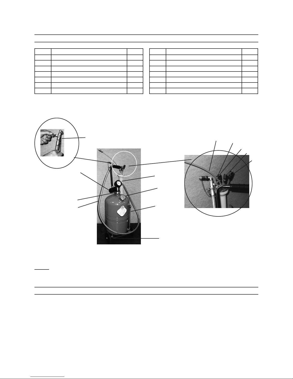
CLOSE BALL VALVE (4) BEFORE5. PRESSURIZATION. Do not attempt
to pressurize Tank (1) with Ball Valve
open.
IF USED OIL DOES NOT6. EVACUATE TANK (1) UPON

Page 4 For technical questions, please call 1-800-444-3353. SKU 46149
PRESSURIZATION, check to make
sure the Ball Valve (4) is fully closed
(with its Handle in the horizontal
position). If this does not correct the
problem remove the unit from service
immediately and have it repaired by a
qualied repair service technician.
DISCONNECT AIR SUPPLY AFTER7. EVACUATING OIL.
USE ONLY THE HOSE/NOZZLE8. ASSEMBLY (5) PROVIDED. Do not
attempt to modify the Hose/Nozzle
Assembly in any way.
THE AIR RELEASE VALVE HAS9. BEEN PRE-INSTALLED AND
PRESET TO OPERATE AT 70-110
PSI. Do not tamper with or remove.
DO NOT DRAIN CAUSTIC OR10. FLAMMABLE PRODUCTS. Do not
expose tank to heat or any ignition
source. Do not do any welding on
or around tank. When removing oil
keep hands and face protected to
prevent against possible burns.
WARNING: The brass components11. of this product contain lead, a
chemical known to the State of
California to cause birth defects (or
other reproductive harm).
(California Health & Safety code §
25249.5, et seq.)
T12. he warnings, cautions and
instructions discussed in this
instruction manual cannot cover
all possible conditions and
situations that may occur. It must
be understood by the operator that
common sense and caution are
factors which cannot be built into
this product, but must be supplied
by the operator.
SPECIFICATIONS
Tank Reservoir Size 6-1/4 Gallons
Maximum Oil Level 4-1/4 Gallons
Maximum extraction
rate 1/2 GPM
Air Inlet 1/4” NPT
Working Air Pressure 70-110 PSI
Min/Max. Oil
Temperature 68-158° F
Oil Extractor Probes
(Total Qty = 5) 1/4” x 27-1/2” Long, Nylon
5/16” x 27-1/2” Long, Nylon
5/16” x 39-1/4” Long, Nylon
1/4” x 27-1/2” Copper
9/32” x 27-1/2” Copper
UNPACKING
When unpacking, make sure that the
item is intact and undamaged. If any parts
are missing or broken, please call Harbor
Freight Tools at 1-800-444-3353 as soon
as possible.
REV 09h

Page 5For technical questions, please call 1-800-444-3353.SKU 46149
OPERATING INSTRUCTIONS
NOTE: All parts below refer to the parts
listed on Page 7 of this manual.
Draining Oil
Locate the extractor on a at, level 1. surface.
Figure A
Ball Valve (4)
(Closed position)
2. Close the Ball Valve (4) on the
Hose (5) by turning its handle to a
horizontal position. See Figure A.
Hand tighten Emptying Cap (9).
Emptying
Cap (9)
Air Inlet
1/4” NPT
Figure B
3. Hook unit up to shop air for
suction. Connect compressed air
(recommended 90 PSI) to coupler.
See Figure B. Never exceed 110 PSI
working air pressure.
Figure C
Mufer
4. Air will ow out of the mufer. See
Figure C. When the arrow on the Air
Pressure Gauge approaches the red
eld, shut-off the shop air compressor
(about 60-80 seconds). The Oil
Extraction Tank is now ready for oil
extraction.
Figure D
Cap
11
(Turn down
to open)
5. Choose the appropriate Probe (7)
(one of ve choices) for the job of
draining the oil. Place Probe in dip
stick area of auto, boat or whatever
needs draining. Remove cap (which
is attached to a chain) off the end
of the Hose (5) and attach it to the
probe inserted in the dip stick tube.
Secure over the two rubber gaskets
in the Assembly. It should feel
secure. See Figure D.

Page 6 For technical questions, please call 1-800-444-3353. SKU 46149
Figure E
11
6. Open the Ball Valve Lever (4) by
turning it vertically; oil will begin to
ow.
Figure F
Oil Level
Tube (8)
Emptying
Cap (9)
7. Oil should be removed when it is
70-80° or personal injury or property
damage may result. The Oil Level
Tube (See Figure F) will show you
how much oil is in the tank. Be sure
to keep the Probe near the bottom of
the sump.
EMPTYING OIL EXTRACTION
TANK
First close Ball Valve Lever (4)1. (Horizontally). Remove Probe from
vehicle.
Detach and close off Hose by putting2. on attached Cap. Disconnect Air
Compressor.
Remove Emptying Cap (9) and3. manually drain oil into an oil recycling
container.
Properly dispose of used oil. Contact4. local Hazardous Waste Disposal
Authorities for proper oil disposable
guidelines.

Page 7For technical questions, please call 1-800-444-3353.SKU 46149
PARTS LIST AND ASSEMBLY DIAGRAM
7B 7C
7D
7E
7A
2
6
5
14
9
8
4
(shown closed)
3
Probes
Note: Some parts are listed and shown for illustration purposes only and are not
available individually as replacement parts.
PLEASE READ THE FOLLOWING CAREFULLY
THE MANUFACTURER AND/OR DISTRIBUTOR HAS PROVIDED THE PARTS DIAGRAM IN THIS MANUAL
AS A REFERENCE TOOL ONLY. NEITHER THE MANUFACTURER NOR DISTRIBUTOR MAKES ANY
REPRESENTATION OR WARRANTY OF ANY KIND TO THE BUYER THAT HE OR SHE IS QUALIFIED TO MAKE
ANY REPAIRS TO THE PRODUCT OR THAT HE OR SHE IS QUALIFIED TO REPLACE ANY PARTS OF THE
PRODUCT. IN FACT, THE MANUFACTURER AND/OR DISTRIBUTOR EXPRESSLY STATES THAT ALL REPAIRS
AND PARTS REPLACEMENTS SHOULD BE UNDERTAKEN BY CERTIFIED AND LICENSED TECHNICIANS
AND NOT BY THE BUYER. THE BUYER ASSUMES ALL RISK AND LIABILITY ARISING OUT OF HIS OR HER
REPAIRS TO THE ORIGINAL PRODUCT OR REPLACEMENT PARTS THERETO, OR ARISING OUT OF HIS OR
HER INSTALLATION OF REPLACEMENT PARTS THERETO.
Part Description Qty
1 Oil Extractor Tank Reservoir 1
2 Air Pressure Gauge 1
3 Air Inlet 1
4 Ball Valve with Lever 1
5 6 Ft. 2-1/2” Long Hose/Nozzle 1
6 Wheels 2
7 5/16” x 39-1/4” Long, Nylon Probe 1
Part Description Qty
8 Oil Level Tube 1
9 Emptying Cap 1
10 1/4” X 27-1/2” Copper Probe 1
11 1/4” x 27-1/2” Long, Nylon Probe 1
12 5/16” x 27-1/2” Long, Nylon Probe 1
13 9/32” x 27-1/2” Copper Probe 1
14 Mufer 1

Page 8 For technical questions, please call 1-800-444-3353. SKU 46149
LIMITED 90 DAY WARRANTY
Harbor Freight Tools Co. makes every
effort to assure that its products meet
high quality and durability standards, and
warrants to the original purchaser that this
product is free from defects in materials
and workmanship for the period of 90 days
from the date of purchase. This warranty
does not apply to damage due directly or
indirectly, to misuse, abuse, negligence or
accidents, repairs or alterations outside
our facilities, criminal activity, improper
installation, normal wear and tear, or to
lack of maintenance. We shall in no event
be liable for death, injuries to persons
or property, or for incidental, contingent,
special or consequential damages arising
from the use of our product. Some states
do not allow the exclusion or limitation
of incidental or consequential damages,
so the above limitation of exclusion may
not apply to you. THIS WARRANTY IS
EXPRESSLY IN LIEU OF ALL OTHER
WARRANTIES, EXPRESS OR IMPLIED,
INCLUDING THE WARRANTIES OF
MERCHANTABILITY AND FITNESS.
To take advantage of this warranty,
the product or part must be returned to
us with transportation charges prepaid.
Proof of purchase date and an explanation
of the complaint must accompany the
merchandise. If our inspection veries
the defect, we will either repair or replace
the product at our election or we may
elect to refund the purchase price if
we cannot readily and quickly provide
you with a replacement. We will return
repaired products at our expense, but if we
determine there is no defect, or that the
defect resulted from causes not within the
scope of our warranty, then you must bear
the cost of returning the product.
This warranty gives you specic legal
rights and you may also have other rights
which vary from state to state.
3491 Mission Oaks Blvd. • PO Box 6009
• Camarillo, CA 93011 • (800) 444-3353
Table of contents
Other Central Pneumatic Scrubber manuals
Popular Scrubber manuals by other brands

Minuteman
Minuteman E17 Parts and instruction manual

Black & Decker
Black & Decker GPC900 manual

BETCO
BETCO Stealth ASD26BT Operator and parts manual

Minuteman
Minuteman Ambassador 20 C8420-115 Operating and service guide

Nilfisk-ALTO
Nilfisk-ALTO SPINTEC 343 operating instructions

Taski
Taski CO150.5 Translation of the original instructions of use

Hillyard
Hillyard TRIDENT R36 SC PLUS Use and maintenance manual

Tennant
Tennant 5500 Pac Operator and parts manual

Numatic
Numatic TRG 720/200T Original instructions

Numatic
Numatic NX 1K Original instructions

Guangzhou Baiyun Cleaning Tools
Guangzhou Baiyun Cleaning Tools A508 product manual

ROBLIN
ROBLIN LINEAR MURALE Instructions for installation