26/96 2016/03 - Indice de révision : E - Code : 0033340
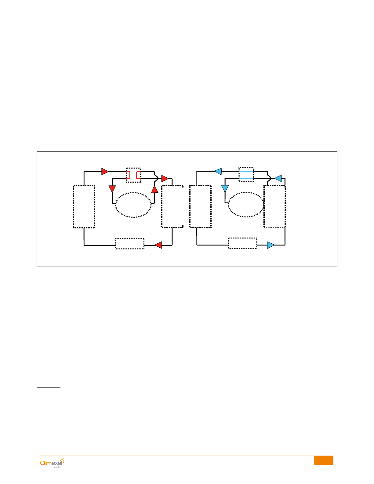
As the ambient air temperature increases, more calories are transferred to the heat transfer fluid at the evaporator, and
then from the heat transfer fluid to the pool water in the condenser. Inversely, as the ambient air temperature falls, less
calories will be available for transfer to the pool water.
To provide a general idea, the following reduction coefficients should be applied to the power values quoted for an
ambient air temperature of 15°C if the machine is operated at lower temperatures.
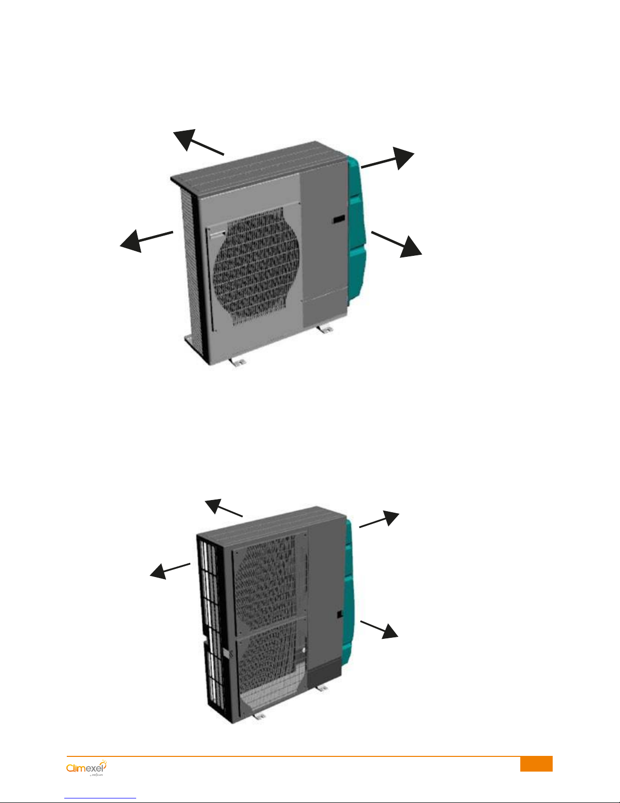
To ensure correct operation and safety, CLIMEXEL heat pumps are fitted with several safety mechanisms:
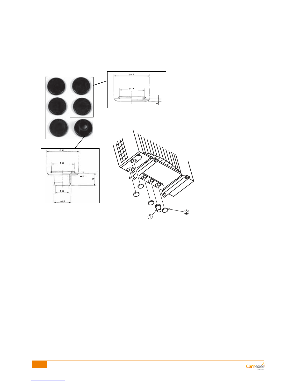
- water flow controller, controls the flow of pool water entering into the condenser: shuts down the heat pump if
the water flow drops below a certain rate or stops completely (not enough calories being transferred from the
heat transfer fluid) ;
- LP pressure gauge, on the LP loop: stops the heat pump if the gas pressure is too low and allows the heat
pump to restart automatically when the pressure returns to normal, within the limit of 3 stop/start cycles per hour,
otherwise switches to fault mode (LP alarm)
- HP pressure gauge, on the HP loop: shuts down the heat pump if the gas pressure is too high, the machine
switches to fault mode;
- CLIMEXEL POWER INVERTER heat pumps feature numerous electronic safety mechanisms.
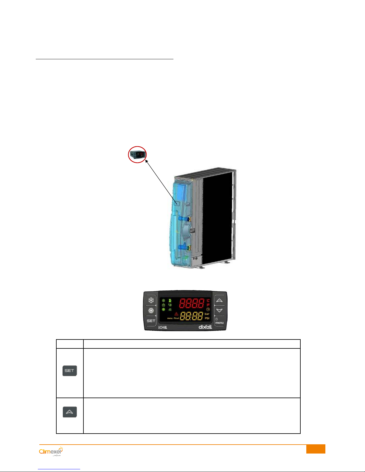
Start up of the compressor and evaporator is controlled by a regulator that allows:
- the user to choose a temperature (the set-point) to which the pool water should be heated;
- automatic start up of the machine if the pool water temperature drops below the set-point (unless filtration is
stopped and is not slaved to the heat pump) ;
- automatic shut down of the machine once the pool water reaches the set-point
- selection of the operating mode; Comfort or Eco
- selection of the configuration; heat or chill the pool water
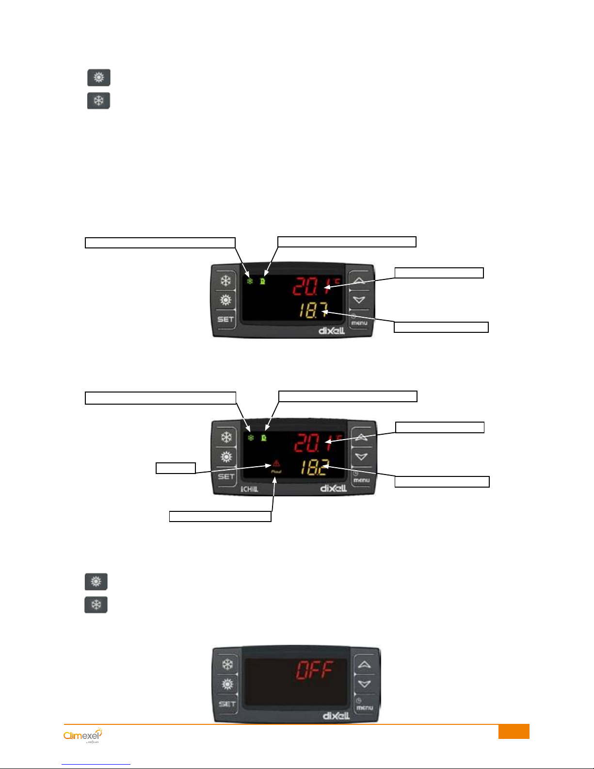
temperature is around the set point, the Inverter compressor runs at low speed (between 11 and 50 Hz).
Operating at low speeds, the noise level is extremely low, the COP is optimised and the service life of the compressor
is extended.
Note: the actual operating range varies depending on the heat pump model.
The power levels or "STEPs" are managed automatically by the machine, they can be viewed from the thermostat
menu. STEPs range from 0 to 7, the higher the STEP the higher the machine's power level.
The machine features a safety mechanism that allows it to switch to a higher power level if it is taking too long for pool
water to reach the set point.
Note:
In Comfort mode, the machine will run at full power until the set point is reached.
In Eco mode, the machine will regulate its power as a function of the air and water temperatures in order to optimise
power consumption. In Eco mode it will take longer for the pool water to reach the set point than in Comfort mode.
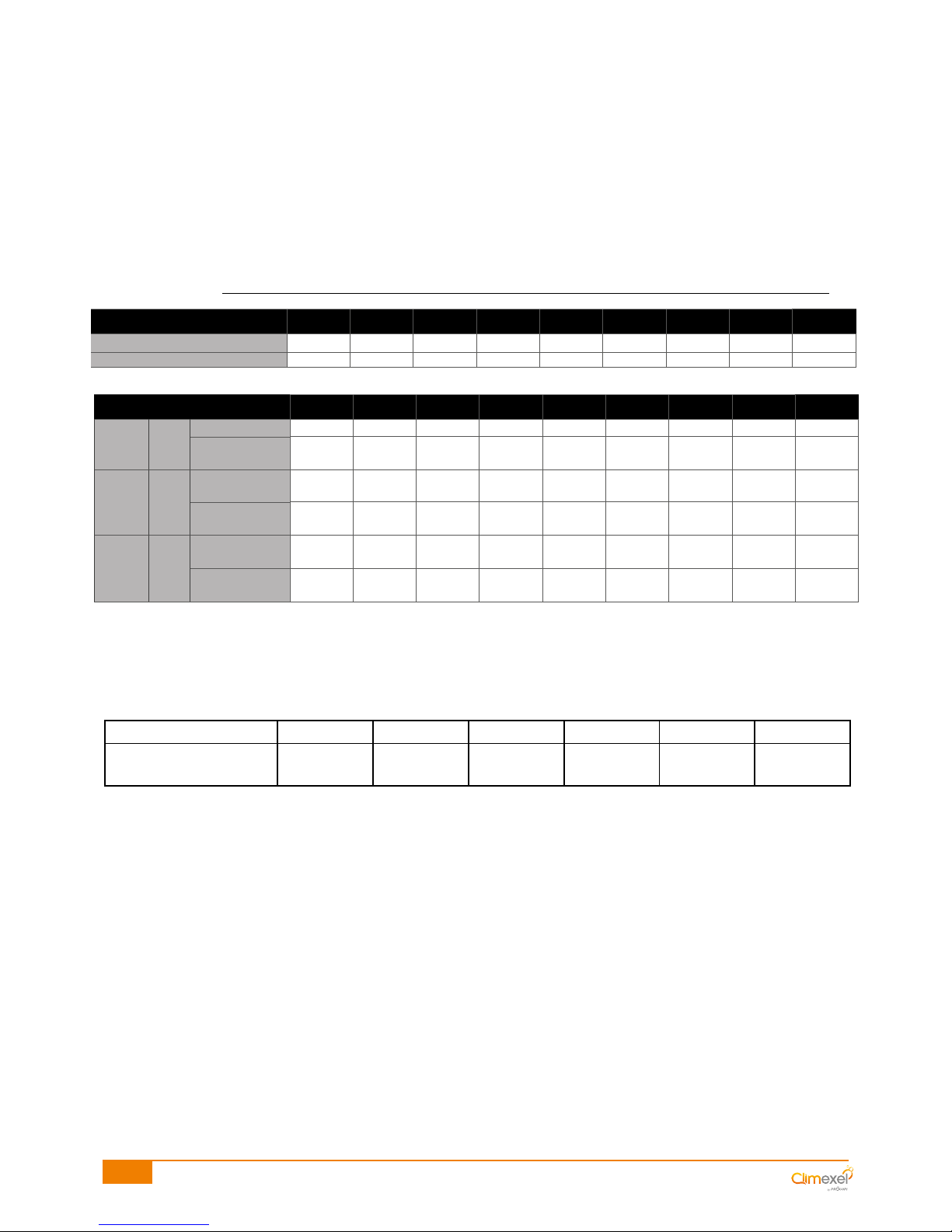
*Values indicated under the following conditions: temperature of the ambient air temperature 15°C and water at 26°C
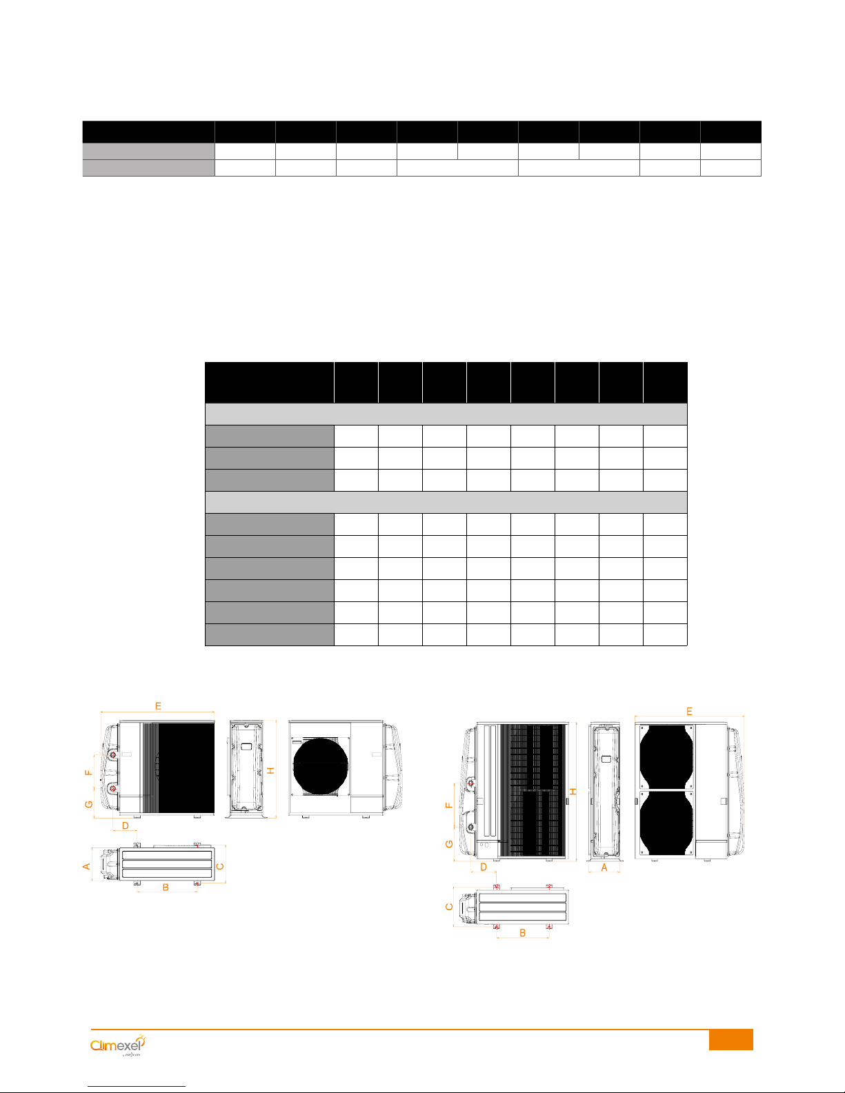
M.P.I.-80M M.P.I.-100M M.P.I.-160M M.P.I.-190M M.P.I.-190T M.P.I.-240M M.P.I.-240T M.P.I.-320T M.P.I.-380T
Maximum heating power* 8 kW 10 kW 16 kW 19 kW 19 kW 24 kW 24 kW 32 kW 38 kW
Quantity of gas 2.1 Kg 2.1 Kg 3.2 Kg 4.6 Kg 4.6 Kg 4.6 Kg 4.6 Kg 7.1 Kg 7.7 Kg
M.P.I.-80M M.P.I.-100M M.P.I.-160M M.P.I.-190M M.P.I.-190T M.P.I.-240M M.P.I.-240T M.P.I.-320T M.P.I.-380T
Low speed STEP 1:
20 Hz
COP 7.5 7.6 7.26 6.86 6.86 6.42 6.42 5.03 4.48
Sound power
(dB(A)) 52 52.8 57.9 55.8 55.8 58.7 58.7 62.9 62.9
Cruising
speed
STEP 4:
50 Hz
COP 6.2 6.3 5.04 5.47 5.47 6.18 6.18 5.3 4.73
Sound power
(dB(A)) 55.6 56.5 61.9 57.8 57.8 62.8 62.8 67.3 67.3
High speed STEP 7:
100 Hz
COP 4.9 5.1 3.75 4.37 4.37 5.34 5.34 4.32 3.87
Sound power
(dB(A)) 62 63 69 68.6 68.6 72 72 76 76
outside temperature (°C) 15 12 7 -7 -10 -15
Maximum power
Climexel MPI (%) 100 % 94 % 82 % 58 % 52 % 44 %