manuals.online logo
Brands
  1. Home
  2. •
  3. Brands
  4. •
  5. BWT
  6. •
  7. Heat Pump
  8. •
  9. BWT HI-HC 66 User manual

BWT HI-HC 66 User manual

24 /76
2019/11– C - Code : 33260
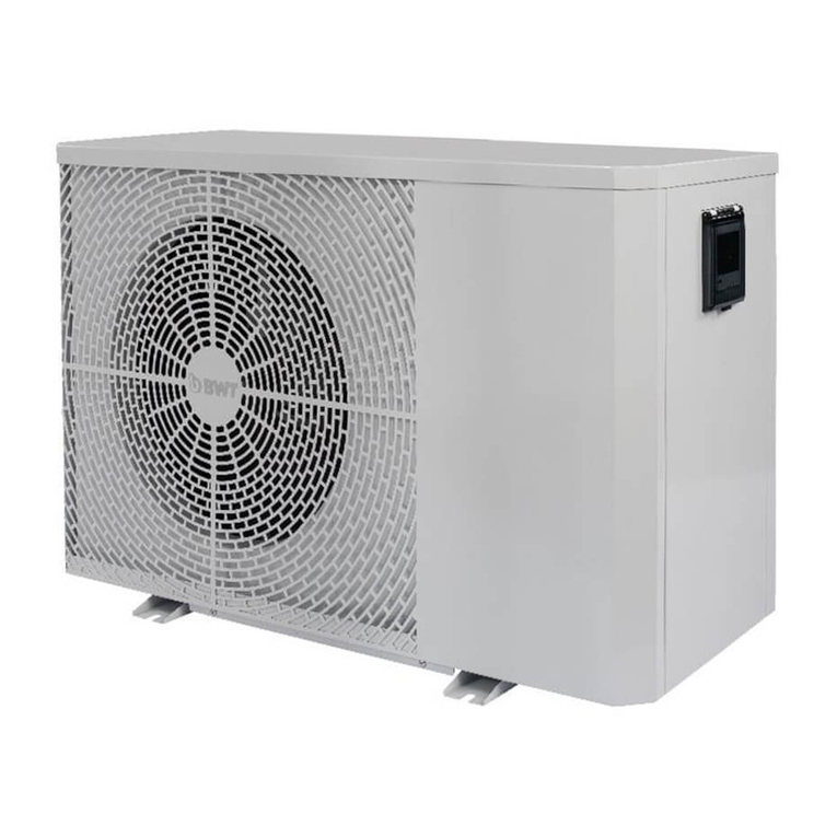
BWT Horizontal Inverter
Heat Pump
HI-HC 66 - HI-HC 85 - HI-HC 106 - HI-HC 132
HI-HC 150 - HI-HC 177 - HI-HC 204 - HI- HC 273
HI-HC 270 - HI-HC 358
25 /76
2019/11– C - Code : 33260
I. Genera product presentation and operating 28
II. Safety recommandations 28
III. Content 28
VII. Technica data and dimensions 29
V. Product insta ation 30
V.1) Siting 30
V.2) Support 31
V.3) Hand ing 31
V.4) Connection to the hydrau ic circuit 31
V.5) Wiring 32
VI. Start up and operation 33
VI.1) Screen ock/un ock : 34
VI.2) Se ecting the operating function : 34
VI.3) Se ecting the set temperature va ue : 35
VI.4) Se ecting the operating mode : 35
VI.5) Defrosting (heating and auto functions on y) 35
VI.6) Wifi setting 36
VIII. Upkeep and maintenance 36
VII.1) Shut down for winterizing: 36
VII.2) – Technica inspections: 36
VII.3) – Spare parts: 36
IX. Error messages 36
X. Troub e shooting 38
X. Wifi setting 39
26 /76
2019/11– C - Code : 33260
Warning:
a. P ease read the fo owing tips before insta ation, use and maintenance.
b. Insta ation, remova and maintenance must be carried out by qua ified professiona in accordance
with the instructions.
c. Gas eakage test must be done before and after insta ation.
1. se
a. It must be insta ed or removed by professiona s, and it is forbidden to dismant e and refit without
permission.
b. Don’t put obstacles before the air inlet and outlet of the heat pump.
2. Installation
a. This product must be kept away from any source of fire.
b. The insta ation can’t be in a c osed environment or indoors, and must be kept we venti ated.
c. Vacuum comp ete y before we ding, we ding can on y be performed by qua ified professiona .
27 /76
2019/11– C - Code : 33260
d. Insta ation must be stopped if any gas eakage.
3. Transportation & Storage
a. Sea ing is not a owed during transportation
b. Transporting goods at a constant speed is needed to avoid sudden acce eration or sudden braking, so
as to reduce the co ision of goods.
c. The unit must be far away from any source of fire.
d. Storage p ace must be bright, wide, open and good venti ation, venti ation equipment is required.
4. Maintenance Notice
a. If maintenance or scrap is required, contact a qua ified professiona nearby.
b. Qua ification requirement :
A operators who dispose gas must be qua ified by va id certification which issued by professiona
agency.
c. P ease strict y comp y with the requirement from manufacturer when maintenance or fi ing gas.
P ease refer to the technica service manua .
28 /76
2019/11– C - Code : 33260
I. General product presentation and operating
BWT Inverter water/ air heat pumps are purpose designed to heat or coo swimming poo s. Performance data
is on y guaranteed for this specific app ication.
Water / air heat pumps are an efficient inexpensive means of heating swimming poo water.
The device exp oits the thermodynamic properties of heat transfer f uids when subjected to the we known
compression – expansion cyc e: owing to its specia properties, the refrigerant recovers ca ories from the
inexhaustib e supp y contained in ambient air, then, after compression and heating, transfers them to the
swimming poo water, thus heating it.
Given that a heat pump transfers heat extracted from outdoor air to the poo water, rather than creating heat
ike a boi er or e ectrica heater a heat pump heats the poo water for 80 % ess than the cost of heating by
other means.
Neverthe ess, in order to further reduce poo heating costs. the poo shou d be covered with an isotherma
cover at night and. more genera y. whi e the poo is not in use. The cover minimises evaporation from the
surface of the water the main source of heat oss.
Despite this, during the co der times of year, it may be necessary to run the heat pump continuous y 24 hours
a day. This is not a cause for concern; heat pumps are designed to run 24 hours a day. Even under these
circumstances a heat pump is a ways cheaper than other conventiona heating means.
Un ike On/ Off heat pumps, Inverter heat pumps can modu ate their operating mode and adapt it to
the swimming poo ’s heating demand. This characteristic makes them even more economica than other
machines, a ows them to run more si ent y in temperature maintenance mode and increases the service ife
of critica components, notab y the compressor.
.
II. Safety recommandations
•Whi e the compressor is working. some elements of the refrigerant circuit
•may become very hot others very cold. Therefore, access to areas ocated
•being the machine’s pane s is restricted to qua ified professiona s.
•Never poke any object through the slots in the grating that protects the
impeller, this cou d damage the impe er.
•Never operate the machine while the impeller’s protective grating is not
in position.
•The distance separating the heat pump and its electrical panel from the water area should be determined
by a qualified professional in accordance with the regu ations in effect in at the insta ation site - See the
recommendations set out in paragraph V.1 and V.3.
•To avoid any risk of danger damaged power cables must be rep aced immediate y by the manufacturer, its
after sa es service or simi ar y qua ified personne .
•Always cut the power supply to the device upstream before any intervention
requiring remova of the pane s or invo ving the hydrau ic connections.
•During storms, cut the power supply to the machine
•When instne in; to dismant e the machine, proceed in the reverse order.
III. Content
Caps for the hydrau ic
unions
Condensate drain
union
Condensate drainage
29 /76
2019/11– C - Code : 33260
VII. Technical data and dimensions
Operating range: outdoor ambient air temperature between -10°C and +43°C.
Performance eve s are maximised between +15°C and +25°C. The machine is not guaranteed to run proper y
outside the -10°C / +43°C operating range.
Water resistance index for e ectrica parts : IPX4.
Set point temperature regu ation range:
•Heating mode: 18°C to 40°C
•Coo ing mode: 12°C to 30°C
Technical data HI-HC
66
HI-HC
85
HI-HC
106
HI-HC
132
HI-HC
150
HI-HC
177
HI-HC
204
HI-HC
273
HI-HC
270 HI-HC 358
Advised water vo ume
(m3) 15~30 20~40 25~45 30~55 35~65 40~75 50~95 65~120 65~120 90~160
Power supp y 230 V / 1 phase / ~ 50 Hz 60Hz 400 V / 3 ph /
~50 Hz 60Hz
max/min consumed
power(kW)*
1
,
11
/
0,13
1
,
2
4
/
0,17
1
,
5
6
/
0,19
1
,
8
7
/
0,24
2
,
2
8
/
0,27
2
,
6
7
/
0,31
3
,
30
/
0,38
3
,
75
/
0,57
3
,
75
/
0,53
5
,
2
0
/
0,62
max/min consumed
current (A)*
4
,
82
/
0
,
56
5
,
39
/
0
,
74
6
,
78
/
0
,
83
8.13
/
1
,
0
4
9
,
91
/
1
,
17
11
,
6
/
1
,
3
4
1
4.3
/
1
,
65
16
,
5/
2
,
4
8
5
,
6
0
/
0
,
7
6
7
,
4
0
/
0
,
8
9
Recommended f owrate
(m3/h)
2 to 4 2 to 4 3 to 4 4 to 6 5 to 7 6,5 to 8,5
8 to 10 10 to 12 10 to 12 12 to 18
Ext. Diam. of hydrau ic
pipe
50 mm
Net weight kg 42 45 49 50 52 63 68 90 93 120
Dim ( ength x width x
height) mm 894 x 359 x 648 954 x 359 x 648 954x429
x 648
954x429
x 755 1084 x 429 x 948 1154 x
539 x 948
Sound power eve dB(A)
at max / midd e / min.
speeds**
61/
53,9/
51,6
62/
55,2/
52,6
63,7/
57,1/
52,4
64,5/
59,5/
55,9
68,8/
60,3/
55,1
67,6/
60,3/
56,9
69/
61,2/
55,7
69,7/
63,2/
58,3
69,7/
63,2/
58,3
69,5/
60,6/
57,4
Refrigerant mass
R 32 (grams) 500 650 750 800 900 1000 1200 2000 2000 2700
Standardised heating performance data according to the standard AFNOR AC-P 90-327 (ex DTP n°10): air temperature 15°C. water
temperature 26°C. relative humidity 70 %
Heating power at max
speed (kW)
5.0 6,2 7,5 9.0 10,5 12.0 14,0 18,0 18,0 24,5
COP at
max / 50 % / min speeds
4,5/6,3/
7,3
5,0/6,6/
7,4
4,8/6,8/
7,7
4,8/6,8/
7,7
4,6/6,6/
7,8
4,5/6,4/
7,8
4,4/6,3/
7,7
4,8/6,8/
8,1
4,8/6,8/
8,1
4,7/7,0/
8,0
Heating performance data. air temperature 26°C. water temperature 26°C. relative humidity 80 %
Heating power at max
speed (kW)
6,6 8,5 10,6 13.2 15,0 17,7 20,4 27.3 27,0 35,8
COP at
max /
50 %
/ min s
peeds
6
,
0/10
,
5
/14
,
7
7
,
4/10
,
9
/14
,
8
7
,
4/11
,
0
/15
,
0
7
,
3/11
,
0
/15
,
4
6
,
7/10
,
9
/15
,
5
6
,
2/11
,
1
/15
,
8
6
,
0/10
,
7
/15
,
3
6
,
5/11
,
2
/15
,
4
6
,
5/11
,
2
/15
,
3
5
,
8/10
,
9
/15
,
6
Cooling performance data. air temperature 35°C. water temperature 28°C. relative humidity 80 %
Coo ing power (kW) at
ma
x speed
3,0 4,0 4,5 5.5 6,8 7,7 9.8 12,1 12,1 16,4
*air 15°C, water 26°C **according to EN 12102 and EN ISO 3744
30 /76
2019/11– C - Code : 33260
Dimensions in mm
Mode A B C D E F G H
HI-HC66
334
590
318
359
894
250
74
648
HI-HC85
334
590
318
359
894
250
74
648
HI-HC106
334
590
318
359
894
2
9
0
74
648
HI-HC132
334
590
318
359
954
28
0
74
648
HI-HC150
334
590
318
359
954
340
74
648
HI-HC177
404
590
388
429
954
390
74
648
HI-HC204
404
590
388
429
954
460
74
755
HI-HC273
404
720
388
429
1084
620
74
948
HI-HC270
404
720
388
429
1084
620
74
948
HI-HC358
514
790
498
539
1154
650
74
948
Nota bene:technical data and dimensions may be subject to modification, without notification, over timedue to
product improvements. For more detail, refer to the information plate on the machine.
When the weather is co d and damp, frost can bui d up on the evaporator fins. This phenomenon is not theresu t of a
ma function; the frost wi be e iminated by automatic triggering of the thermodynamic defrostingcyc e (inversion of
the refrigerant cyc e). Once the frost has been me ted, the machine wi revert to norma operating mode.
The heat pump is fitted with a f ow contro er that on y a ows the machine to start up when the water f owrate
through the machine is adequate (see the recommended va ues in the technica data tab e).
V. Product installation
V.1) Siting
The fo owing points must be taken into consideration:
•The device must be installed outdoors
•Condensate drainage
Connect the e bows and the condensate drainage hose to the ho e in the machine f oor such that the
condensates wi be channe ed to waste. Do not mix condensates with the poo water.
•Distance from the water area
The distance must satisfy the stipulations of the local regulations
if effect at the installation site. However, this distance shou d not
be so great that the ength of the pipes makes it impossib e to
achieve the minimum water f ow rate necessary for correct
operation of the machine.
•Clearance
The minimum recommended c earances between each surface of
the machine and the nearest obstac e (wa , partition, hedge, etc.)
are shown as indicated :
The machine shou d not be ocated in a corner where air
circu ation and renewa cou d be hindered.
31 /76
2019/11– C - Code : 33260
Pay attention to the proximity of deciduous vegetation. Leaves, f owers, po en, etc. cou d be drawn in by the
fans and obstruct the gratings.
•Proximity to neighbours
Quite apart from the heat pump’s intrinsic acoustic eve , (measured in a aboratory according to
standardized methods and on standardised insta ations) the insta er is responsib e for ensuring that the
insta ation site wi not cause a phonic nuisance to neighbours, and take any necessary steps.
Refer toany oca ru es that app y.
•Soil moisture
The heat pump must not be insta ed in a ocation where precipitation can accumu ate and gather in
pudd es around the machine.
Condensates generated by the heat pump whi e it is running must be drained away (use the drain
connectionenc osed), and must not accumu ate around the machine.
•/30
•Installation height
If the machine is wa mounted, the intrinsic strength of the wa and the mounting must be sized, with
asafety margin, to bear the weight of the machine when fi ed with water. Take exposure to prevai ing
windsinto consideration. Mounting brackets must be treated against corrosion. Piping must be attached to
the wa to be supported (but not by the machine).
Make sure the fi tration pump can overcome the height difference between the fi tration pump and the
heatpump. Take any necessary steps (increase pump power, additiona pump, etc.).
V.2) Support
The heat pump must be attached by its feet to a so id, stab e and horizonta base (stain ess stee M
10screws). A s oped position cou d interfere with the f ow of condensates.
In the interest of noise abatement, the machine and pipes connected to it must be insta ed in such a waythat
they do not vibrate whi e running.
V.3) Handling
Never ift the machine by its hydrau ic unions.
Do not store the machine ying on its side. If the machine was aid on its side,
put it upright after storage,
and eave it stand ike this, switched off, for at
east 48 hours.
V.4) Connection to the hydraulic circuit
The heat pump must be mounted on a
fi tration circuit by-pass, downstream from
the sand fi ter, andupstream from the
injection of any treatment chemica s (the
titanium condenser is resistant to di ute poo
chemica s, but is not guaranteed against
exposure to high concentrations of poo
chemica s).
The bypass oop must be fitted with three
va ves, one on the bypass intake, one on the
bypass out et(iso ation va ves) and one
between the two tapping points (va ve to
32 /76
2019/11– C - Code : 33260
contro the f ow rate through the heat pump).
To imit heat oss from the pipes, bury them underground (at a depth of 50 to 80 cm depending on the
region) or ag the pipes. In any case, minimize the amount of uninsu ated pipe exposed to the air.
V.5) Wiring
The machine must be wired in by a qua ified professiona , after the hydrau ic connections have been
comp eted. When dismant ing the machine, disconnect it e ectrica y before disconnected the hydrau ic
connections.The heat pump’s power cab e connection termina is ocated behind the socket. Use a cab e with a
wirecross section that comp ies with the specification be ow, connected upstream to a breaking device rated
as set out in this tab e.
HI-HC
66
HI-HC
85
HI-HC
106
HI-HC
132
HI-HC
150
HI-HC
177
HI-HC
204
HI-HC
273
HI-HC
270
HI-HC
358
Therma magnetic
circuit breaker rating(A) 9.0 10.5 12.0 14.5 16.5 18.0 21.0 24.0 9.0 12.0
bipolar tetrapolar
Residua current device sensitivity 30 mA max
bipolar trtrapolar
Power cab e (wirecross
section in mm2) 3 x 1,5 3 x 2,5 3 x 2,5 3 x 2,5 3 x 2,5 3 x 4,0 3 x 4,0 3 x 6,0 5 x 2,5 5 x 2,5
Remote insta edcontro
pane cab e(wire cross
section inmm2)
3 x 0.5
*For a cable length less than 10 m. Increase the wire cross section if the cable is more than 10 m long. The cable
length should never exceed 50 m.
!IMPORTANT :
Damaged cab es must be rep aced immediate y by a qua ified professiona .
When insta ing the device, make sure earth wiring wi present an ohmic resistance eve comp ying with oca
regu ation requirements.
Check the e ectrica connections at the various termina s annua y, tighten if necessary.
The heat pump’s e ectrica and e ectronic components are not guaranteed against overvo tages produced by
ightning strikes. The e ectrica supp y in the home must be adequate y protected against this risk.
①Unscrew the 2 screws from the base of the pane on
the right hand side and remove the bottom section
of the pane .
②Remove the 3 screws from the id of the e ectrica box.
③Connect the power cab e according to the standardised
markings (NB: in 3ph insta ations, ive wires are marked
R,S,T / in 1 phinsta ations, the ive wire is marked L).
33 /76
2019/11– C - Code : 33260
V.6) Heating priority :
It is possib e to set the system up so that the heat pump wi start up fi tration outside programmed
fi tration cyc es if a heating demand is detected. This a ows the poo water temperature to be he d more
constant y around the set point.
In this case, the heat pump wi start the fi tration up every our (un ess it is a ready running) to measure
the poo water temperature. If a heating demand is detected, it keeps the fi tration pump running,
otherwise it stops the fi tration pump after 3 minutes.
To do this, the e ectrica connections to be made wi use the termina s marked P1 and P2 on the heat
pump termina b ock:
Next, activate heating priority as fo ows on the contro pane :
•Press the and icons simu taneous y for 5 seconds to access the parametermodification menu.
•The “P0” parameter fo owed by “0” is disp ayed on the screen: “P0 0”.
•Press to modify P0, then press to scro unti 1 is disp ayed : “P0 1”
•Press once again to confirm,
•Press to exit the parameter modification menu.
To eave the heating priority mode, set the P0 parameter back to 0 fo owing the above procedure.
!IMPORTANT : do not modify the value of parameters other than P0
VI. Start up and operation
After verifying that there is an adequate f ow rate through the machine, press the
start (and stop) icon for 3 seconds to activate the screen, then press on to
start the heat pump. Where the machine detects the need to heat the water, in the
fo owing 3 minutes, the fan si start, fo owed by the compressor after about 30
seconds.
~ 230 V, 50 Hz
6
0 Hz
DDR 30 mA
Therma magnetic
circuit
breaker
Fi tration pump
Switch
coi
Power
contacts
Therma magnetic circuit breaker
~ 230 V (mono) ou 400 V
(tri) , 50 Hz 60 Hz
Fi tration
timer
L
N
Earth
P1
P2
Heat pump
34 /76
2019/11– C - Code : 33260
Symbol Designation Function
ON/OFF 1.Power on/off
2.Wifi setting
Lock-un ock /
Mode se ection
Locking / un ocking the screen
Mode se ection
Speed Se ect Smart/Si ence mode
Up / Down Adjust set temperature
Notes :
Screen automatica y ocks after 30 s without any operation with it
When screen is ocked :
a. the buttons are not disp ayed except the un ock one
b. when the heat pump is off, screen is dark and “0%” is disp ayed
VI.1) Screen lock/unlock :
- If screen is locked, press for 3 seconds to unlock it, buttons and icons are displayed
- If screen is unlocked, also press for 3 seconds to lock it, it shuts off ( still lit)
VI.2) Selecting the operating function :
There are three operating functions avai ab e (heating/ coo ing /auto) :
•If the auto function is active ( ), the machine wi automatica y go into heating or coo ing mode
depending on the difference between the actua poo water temperature and the set point temperature: if
the water is co der than the set point temperature, heating mode wi be activated, if the water is warmer
than the setpoint, coo ing mode wi be activated.Thus, the heat pump wi automatica y keep the water
temperature at the set point va ue.
When this function is active, the set temperature can be fixed between 12 and 40°C.
•The heating function on y enab es to increase the water temperature.If the water temperature
overpasses the set va ue due to the ambiant conditions, the heatpump keeps off, and wi not coo the water.
W
ater temperature
at the in et
Coo ing indicator
Auto mode icon
Heating indicator
Current power, in %
of max. power
Compressor running
W
ater temperature
at the out et
Smart/Si ence
mode
Water at the in et
Water at the ou et
Wifi Signa
35 /76
2019/11– C - Code : 33260
Thus, this function is to be activatedon y when the poo water temperature is ike y to decrease
spontaneous y.
When this function is active, the set temperature can be chosen between 18 and 40°C.
•The coo ing function on y enab es to decrease the water temperature. If the water temperature fa s
under the set va ue due to the ambiant conditions, the heatpump keeps off, and wi not heat the water.
Thus, this function is to be activated on y when the poo water temperature is ike y to increase
spontaneous y.
When this function is active, the set temperature can be chosen between 18 and 30°C.
The indicator showing the active function is disp ayed eft in the upperpart of the screen when un ocked.To modify
it, press once or severa times unti the icon of the expected function is disp ayed.
Note :the function u timate y se ected by the operator wi be active when restarting the heat pump after being off.
VI.3) Selecting the set temperature value :
Screen being un ocked, press or to disp ay the set temperature, and then to change its va ue with these same
arrows.
VI.4) Selecting the operating mode :
The heat pump has 2 operating modes, each has its own specific advantages:
When the heat pump is started up (by pressing the On/ Off button), it enters SMART mode by defau t (the
corresponding icon is disp ayed on the screen)
Press the key to switch to SILENCE mode (the corresponding icon is disp ayed on the screen)
To revert to SMART mode, press the key again.
Pressing this key wi togg e between the two operating modes.
VI.5) Defrosting (heating and auto functions only)
The heat pump is designed such as it automatica y detects when a defrosting cyc e is needed. In such a case, the
defrosting cyc e starts, and stops automatica y.
When the heat pump is busy heating the water, the operator can a so starts a defrosting cyc e manua y if it appears
suitab e (for examp e, where a high amount of frost has not been tota y e iminated by the defrosting cyc e). For this,
press and simu taneous y for 5 seconds.
f ashes during a defrosting cyc e.
Mode Recommandation Caractéristiques
Smart
Standard operating
mode, used to raise
the poo water
temperature to the set
point
Heating power is modu ated between
25% and 100%, to heat or coo the
water rapid y if a high power demand is
detected
Si ence Proximity of
neighbourg
Heating power is modu ated between
25% and 80%, the machine’s noise
emission sound output is reduced 3dB
(A) compared to operation at 100%
power
36 /76
2019/11– C - Code : 33260
Note : do not start a manua defrosting cyc e if :
-Compressor has not been running continuous y for at east 10 minutes
-Less than 30 minutes after a defrosting cyc e has stopped.
VI.6) Wifi setting
P ease kind y check the ast page.
VIII. pkeep and maintenance
Check the evaporator fins regu ar y for debris ( eaves, f owers, po en, etc.), c ean the fins with a soft brushand soapy
water or with ordinary detergents. Do not use so vants.Check the condensate drainage tubes for obstructions
(water f owing around the machine).The machine cabinet may be c eaned with soapy water or ordinary detergent.
Do not use so vants.
VII.1) Shut down for winterizing:
If fi tration is shut down to winterize the poo , or if the water is not heated during active winterization:
• Cut e ectrica power to the machine (therma magnetic circuit breaker set to off).
• C ose the 2 iso ation va ves on the heat pump bypass oop.
• Unscrew the 2 hydrau ic unions to drain a water from the machine, and then cover these with the
caps provided (to avoid any unwanted guests taking up residence over the winter period).
• Cover the machine, if possib e, to prevent dirt from bui ding up on the externa parts.
VII.2) – Technical inspections:
The insta ation shou d be inspected once a year by a technician qua ified to hand e refrigerants.
Check that e ectrica and hydrau ic connections are correct y tightened.
Depending on the mass of refrigerant inside the machine, regu ations may require that the refrigerant circuit be
regu ar y inspected for eaks. Refer to the oca regu ation on that topic. The inspection certificate must be kept.
VII.3) – Spare parts:
Spare parts specific to BWT heat pumps, and essentia for them to run correct y, wi be avai ab e for at east 5 years
after the date of purchase of the machine (minimum duration in the event that the product is withdrawn from the
market).
IX. Error messages
Some errors do not cause the compressor to stop, but are disp ayed on screen (some wi a so generate an aura
a arm) for 3 minutes every 30 minutes unti either the prob em is reso ved, or the machine is stopped using the On/
Off button.
Other more critica errors wi stop the compressor. The power supp y to the machine must be disconnected before
proceeding with the repair. Upon restarting the machine, the error is reset and on y reappears if the prob em has
not been reso ved. Error messages associated with abnorma operating conditions are shown in bo d in the fo owing
tab e.
37 /76
2019/11– C - Code : 33260
NO. Displayed code Not Fault description
1 E3 No water protection
2 E5 Power supply excesses operation range
3 E6 Excessive temp difference between inlet and outlet water(Insufficient water flow protection)
4 Eb Ambient temperature too high or too low protection
5 Ed Anti-freezing reminder
NO. Displayed code Fault description
1 E1 High pressure protection
2 E2 Low pressure protection
3 E4 3 phase sequence protection (three phase on y)
4 E7 Water out et temp too high or too ow protection
5 E8 High exhaust temp protection
6 EA Evaporator overheat protection (on y at coo ing mode)
7 P0 Contro er communication fai ure
8 P1 Water in et temp sensor fai ure
9 P2 Water out et temp sensor fai ure
10 P3 Gas exhaust temp sensor fai ure
11 P4 Evaporator coi pipe temp sensor fai ure
12 P5 Gas return temp sensor fai ure
13 P6 Coo ing coi pipe temp sensor fai ure
14 P7 Ambient temp sensor fai ure
15 P8 Coo ing p ate sensor fai ure
16 P9 Current sensor fai ure
17 PA Restart memory fai ure
18 F1 Compressor drive modu e fai ure
19 F2 PFC modu e fai ure
20 F3 Compressor start fai ure
21 F4 Compressor running fai ure
22 F5 Inverter board over current protection
23 F6 Inverter board overheat protection
24 F7 Current protection
25 F8 Coo ing p ate overheat protection
26 F9 Fan motor fai ure
27 Fb Power fi ter p ate No-power protection
28 FA PFC modu e over current protection
38 /76
2019/11– C - Code : 33260
X. Trouble shooting
The fo owing tab e describes situations that may seem abnorma a though no error code is disp ayed on the
machine. For any other prob ems, p ease contact the se er.
Problem Possibles causes Possible solutions
The heat pump wi
not
start
No power supp y
Check that no circuit breakers are
tripped
Check that the e ectrica connections
are not oose.
The machine is off Press the On/ Off button.
The temperature set point
has
been over shot
Check the set point temperature,
compare this with the water temperature at the
in et.
The heat pump is
running, but the poo
water temperature is
not changing
Heat oss is too high
Make sure th
at the poo is covered with
an isotherma cover whi e it is not in
use.
Make sure that pipes connecting the
heat pump to the poo are buried at the
correct depth, or are correct y agged.
In the case of above
-
ground poo s,
check that the heat oss from the poo
wa s is not too high.
The dai y run time is too
short
given the coo ness of
ambient air
Inadequate programming of the timer
that contro s fi tration start and stop:
- Length of the fi tration cyce too short
- Fi tration on y at night when the
ambient T°C is particu ar y ow
The ambient air
temperature is
exceptiona y ow
Wait unti the temperature returns to
norma eve s.
Check that the machine is correct y
sized for the water vo ume and period
of use.
Air is not circu ating free y
Check that the evaporator fins are
c ean.
Check that the insta ation instructions
set out in paragraph IV.1 have been
respected
The heat pump trips
the
magnetic therma
circuit
breaker is an
untime y
manner
Circuit breaker incorrect y
set
Check that it is set in accordance with
recommendations set out in paragraph
IV.3
E ectrica short circuit
Have the heat pump e ectrica wiring
and its power supp y checked by a
qua ified e ectrician.
Circuit breaker common to
severa devices and under
sized
Insta a circuit breaker specific to
the hat pump in accordance with the
recommendations set out in paragraph
IV.3
The heat pump trips
theRCD Earth eakage current
Have the heat pump e ectrica wiring
and its power supp y checked by a
qua ified e ectrician.
39 /76
2019/11– C - Code : 33260
X. Wifi setting
1) APP Down oad
Android mobi e p ease down oad from iphone p ease down oad from
2) Account registration
a) Registration by Ce phone number/Emai
40 /76
2019/11– C - Code : 33260
b) Ce phone number registration
3) Create fami y
P ease set fami y name and choose the room of device
4) APP Binding
P ease make sure your ce phone has connected the Wifi
a) Wifi connection:
Press for 3 seconds after screen un ock, wi be f ashing to enter Wifi binding program.
41 /76
2019/11– C - Code : 33260
b) C ick "Add device", fo ow indication to finish binding. disp ay on the screen once Wifi connection
success.
42 /76
2019/11– C - Code : 33260
c) If connect fai s, p ease make sure your network name and password is correct. And your router, mobi e
phone and device are as c ose as possib e.
d) Wifi rebinding (When Wifi password changes or network configuration changes):
Press for 10 seconds, wi be f ashing s ow y for 60 seconds. Then wi be off. The
origina binding wi be removed. Fo ow step above for rebinding.
Remarks: P ease make sure the router is configured at 2.4G.
5) Operation
For heat pump with Heating & Coo ing function.
Share
More
share devices
Indicate the
statusof Heating / Cooling
Heating capacity
percentage
Select ℃/℉
The current
swimming pool
water temperature
Select Heating/
Cooling Function
The setting
temperature
Timer
Select Smart/
Silence Mode
On/Off
43 /76
2019/11– C - Code : 33260
6) Share devices to your fami y members
After binding, if your fami y members a so want to contro the device.
P ease et your fami y members register the APP first, and then the administrator can operate as be ow:

This manual suits for next models

9

Other BWT Heat Pump manuals

BWT Inverter Connect User manual

BWT

BWT Inverter Connect User manual

BWT FI CONNECT EF 55 User manual

BWT

BWT FI CONNECT EF 55 User manual

BWT PEARL HPF09 User manual

BWT

BWT PEARL HPF09 User manual

BWT FI Series manual 

BWT

BWT FI Series manual 

BWT PEARL HPT 12 User manual

BWT

BWT PEARL HPT 12 User manual

BWT SHP2.5 ON/OFF User manual

BWT

BWT SHP2.5 ON/OFF User manual

BWT myPOOL MP-IPH 50 User manual

BWT

BWT myPOOL MP-IPH 50 User manual

BWT PEARL HPF User manual

BWT

BWT PEARL HPF User manual

Popular Heat Pump manuals by other brands

Strebel S-ASX.21 60 Installation operating & maintenance manual

Strebel

Strebel S-ASX.21 60 Installation operating & maintenance manual

Carrier 38AYC Series Product data

Carrier

Carrier 38AYC Series Product data

Carrier AquaSnap 61AF-A Installation, operation and maintenance instructions

Carrier

Carrier AquaSnap 61AF-A Installation, operation and maintenance instructions

SERO AWB-SS-15 DC Installation and maintenance manual

SERO

SERO AWB-SS-15 DC Installation and maintenance manual

Dimplex LA 9TU Installation and operating instructions

Dimplex

Dimplex LA 9TU Installation and operating instructions

MICROWELL HP 1100 GREEN INVERTER PRO Installation and user manual

MICROWELL

MICROWELL HP 1100 GREEN INVERTER PRO Installation and user manual

BMC GW024 installation instructions

BMC

BMC GW024 installation instructions

Carrier 38YCC Series Installation and start-up instructions

Carrier

Carrier 38YCC Series Installation and start-up instructions

GEA SHA series Assembly instructions

GEA

GEA SHA series Assembly instructions

Lennox ML14XC1 Series Installation and service procedure

Lennox

Lennox ML14XC1 Series Installation and service procedure

Carrier COMFORT SERIES 25HCB3 Product data

Carrier

Carrier COMFORT SERIES 25HCB3 Product data

ClimateMaster V-W Installation, operation and maintenance instructions

ClimateMaster

ClimateMaster V-W Installation, operation and maintenance instructions

Carrier 25VNA8 infinity 18VS installation instructions

Carrier

Carrier 25VNA8 infinity 18VS installation instructions

Leader Evaporator Half Pint Evaporator manual

Leader Evaporator

Leader Evaporator Half Pint Evaporator manual

Panasonic 2WAY Multi Series Technical & service manual

Panasonic

Panasonic 2WAY Multi Series Technical & service manual

Altherma EKHBH007A installation manual

Altherma

Altherma EKHBH007A installation manual

STIEBEL ELTRON WPL 15 IKS-2 Operation and installation

STIEBEL ELTRON

STIEBEL ELTRON WPL 15 IKS-2 Operation and installation

Idea ISW-10 SF1-DN1 installation manual

Idea

Idea ISW-10 SF1-DN1 installation manual

manuals.online logo
manuals.online logoBrands
  • About & Mission
  • Contact us
  • Privacy Policy
  • Terms and Conditions

Copyright 2025 Manuals.Online. All Rights Reserved.