CNC FACTORY V300 Series User manual
[USER GUIDE]
V300 SERIES VACUUM PUMP

User Guide © CNC Factory | Rev04222021
2
V300 SERIES VACUUM PUMP
LEFT SIDE
Grease Gun
MPa Gauge
& Valve
Filter
Filter
In-line Filter
In-line Filter
RIGHT SIDE
TOP VIEW

User Guide © CNC Factory | Rev04222021
3
V300 SERIES VACUUM PUMP
Please follow all the guidelines under this manual pertaining to the installation,
operation and maintenance of your V300 Series Vacuum Pump (“V300 Pump” or
“pump”).
To move the V300 pump, only use the lifting bolts on top of the pump. Verify the tightness of the rigging
before moving. The V300 pump always requires dry storage.
Install the V300 pump in a position for
easy maintenance access. However,
it should be 12” away from any wall or
obstacle to ensure that airflow and
cooling is not impeded. The ambient
temperature should not exceed 110
degrees.
The V300 Pump produces hot temperatures on the pump and the air exiting the pump.
To avoid contact with its hot surfaces:
• Install the pump in the proper, upright position on a stable surface. Allot a
minimum 12” clearance on all sides of the pump.
• Install warning signs around and/or block accidental access to the pump
via enclosures or barriers
• The V300 pump can be used to generate a vacuum (KVE).
• The V300 pump is a dry vane pump and does not require oil. It cannot be used with toxic or flammable
materials.
• Its inlet takes in dry, clean air free of dust and debris. Air with dust and debris will lead to internal vane
and structural damage and degrade the pump’s performance.
GENERAL
TRANSPORT AND STORAGE
INSTALLATION
READ BEFORE INSTALLATION

User Guide © CNC Factory | Rev04222021
4
V300 SERIES VACUUM PUMP
The in-line vacuum filter should always be used to help capture
any dust or debris. Having an in-line filter between the pump
and machine ensures proper operation of your pump. During
the initial installation, check the filter chamber and blow off/
remove any debris. For many new installations, there is usually
some leftover debris from the machine hose or vacuum table.
Make sure to check the in-line filter at least once a month.
IN-LINE FILTER
The V300 pump comes with fittings for 3”. The vacuum hose
should not exceed a 20’ distance between the machine
manifold and the air in-line filter.
VACUUM HOSE DIAMETER
Before installing the machine, consider the availability and proximity of the required power supply circuit.
If an existing circuit does not meet the requirements of this machine, a new circuit must be installed. To
minimize the risk of fire or equipment damage, electrical work must be done by a licensed electrician or
qualified service personnel in accordance with all applicable codes and standards.
ELECTRICAL CONNECTION
The full-load current rating is the amperage the V300 pump draws at 100% of the rated output power. On
machines with multiple vacuum motors, this is the amperage drawn by the sum of all vacuum motors and
any electrical device that might operate at the same time.
FULL-LOAD CURRENT RATING

User Guide © CNC Factory | Rev04222021
5
V300 SERIES VACUUM PUMP
220 Volt Configuration 380 Volt Configuration
• The number of switches (turning the machine on
and off) per hour should not exceed 6 times
• Once power is installed, turn on the machine to
allow the motor to slightly turn. Then, check is the
rotation is correct (it should match the directional
arrows on the vacuum pump case). If the rotation
is incorrect, switch a wire leg at the terminal.
Configure the wiring and disconnect according to the electric motor configuration and model:
Model V300: Full-Load Current Rating at 220V…..40 Amps
Model V300: Full-Load Current Rating at 380V…..32 Amps
Model V340: Full-Load Current Rating at 480V…..25 Amps
Model V340: Full-Load Current Rating at 720V…..12.5 Amps
Directional Arrows
User Guide © CNC Factory | Rev04222021
6
V300 SERIES VACUUM PUMP
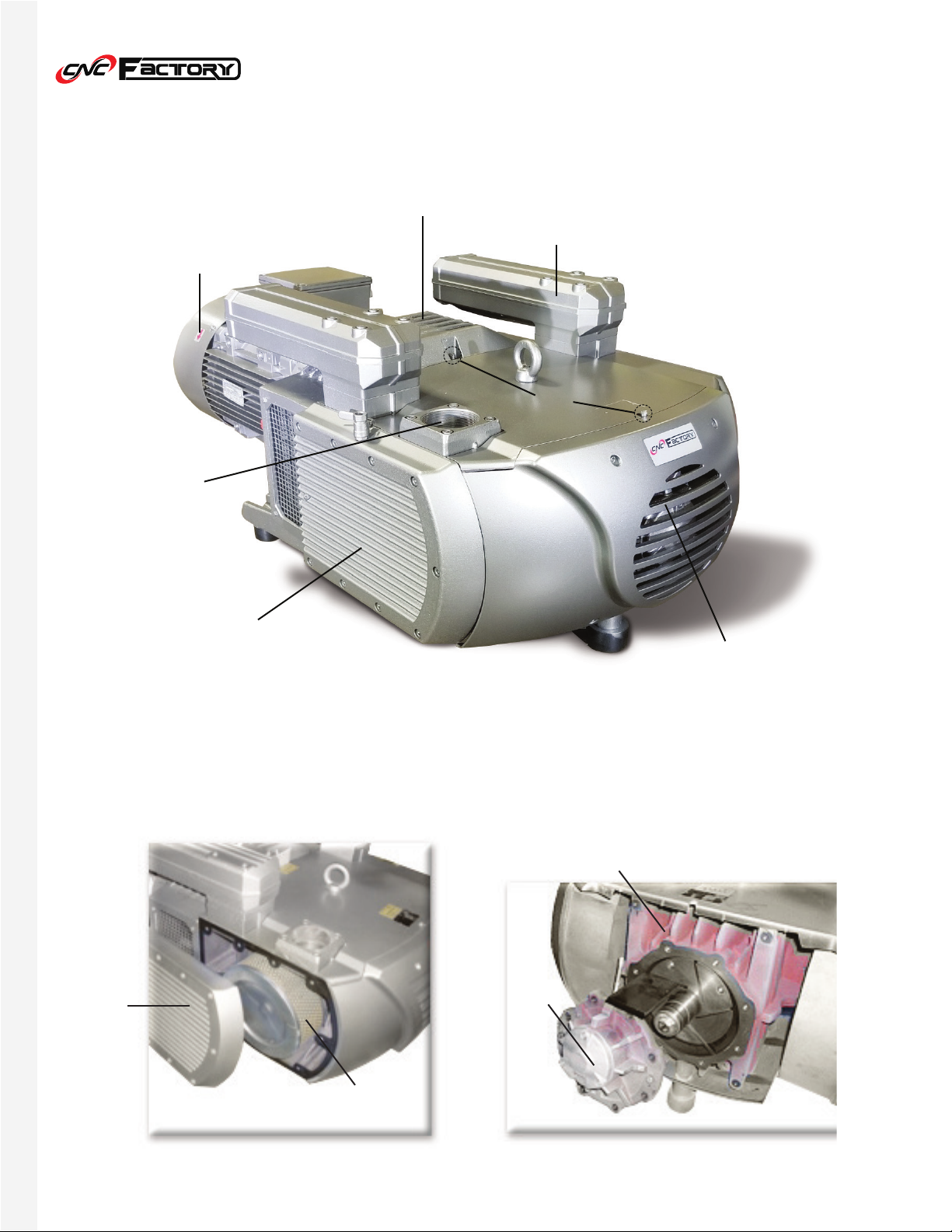
GENERAL PUMP DESCRIPTION
KL: Cylinder Air Duct
SD: Rear Inner Vane Cover
BC: Vacuum Air Intake
SA: Vacuum Access Port
GD: Side Filter Cover
SV: Vacuum Air Safety Valve
AS: Vacuum Silencer
SN: Grease Inlet
LH: Rear Pump Cover
GD
SA
SV AS
LH
BC
SN
KL
SD
GD
FILTER
User Guide © CNC Factory | Rev04222021
7
V300 SERIES VACUUM PUMP
Hose or
PVC Pipe
Air
Filter
Single
Direction Valve
Bypass
Port
Power
Box
Exhaust
Port
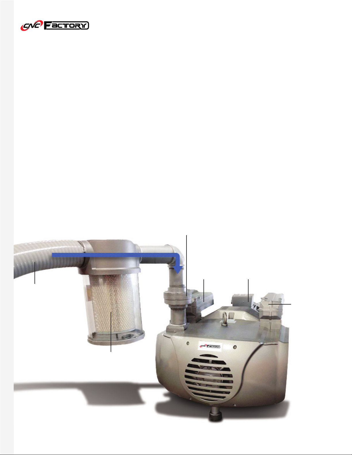
FILTER ASSEMBLY
Assemble the pump as shown below. The blue arrow indicates the air flow direction. The air filter and
single direction valve both have directional arrows marking the correct direction. Make sure they match
with the blue arrow.
Remove all plastic protection covers on both ports before powering on the pump. Use Teflon tape on all
pipe thread; be careful not to over thread the pipe.

User Guide © CNC Factory | Rev04222021
8
V300 SERIES VACUUM PUMP
Regular maintenance of the V300 pump allows it to maintain optimum operating conditions. Each
maintenance cycle depends on how much the pump is used as well as its work environment (i.e. degree
of dust generated and hours used). Minimum maintenance should be performed monthly until a regular
maintenance schedule can be established based on your usage and environment.
Before performing maintenance or servicing your V300 pump, disengage the electrical
power to the pump to ensure there is no chance for an accidental start.
The filter cartridge is installed behind the side
cover (GD location) and is cleaned to remove
dust and debris accumulation. When cleaning,
use compressed air to clean the filter inside out.
Adjust your maintenance schedule based on dust
and debris accumulation here. A clean side filter
is crucial to proper operation and warranty
coverage!
The filter cartridge is installed inside the vacuum
intake housing (GD location) and is cleaned to
remove dust and debris accumulation. When
cleaning, use compressed air to clean the filter
inside out. Adjust your maintenance schedule
based on dust and debris accumulation here. A
clean vacuum intake filter is crucial to proper
operation and warranty coverage!
MAINTENANCE
Standard Scheduled Maintenance:
Cleaning the Intake Filter
Cleaning the Vacuum Intake Filter

User Guide © CNC Factory | Rev04222021
9
V300 SERIES VACUUM PUMP
Blow compressed air into the cylinder air duct (KL
location) to remove any build up.
Cleaning the Cylinder Air Duct
Lubrication
The V300 pump requires lubrication every 300
hours of use to ensure enough grease to lubricate
its bearings. Install grease at both SN locations until
the grease starts to back out from the input plug. For
new installations, lubricate after the first 3 months of
use. Your vacuum includes a grease gun. Refills can
be purchased from CNC Factory or at most hardware
stores. Regular lubrication is crucial to proper
operation and warranty coverage!
Use Klüber PETAMO GY 193
lubrication. Apply 5 grams to
each grease port.
Use
lubrication. Apply 5 grams to
each grease port.
SN
User Guide © CNC Factory | Rev04222021
10
V300 SERIES VACUUM PUMP
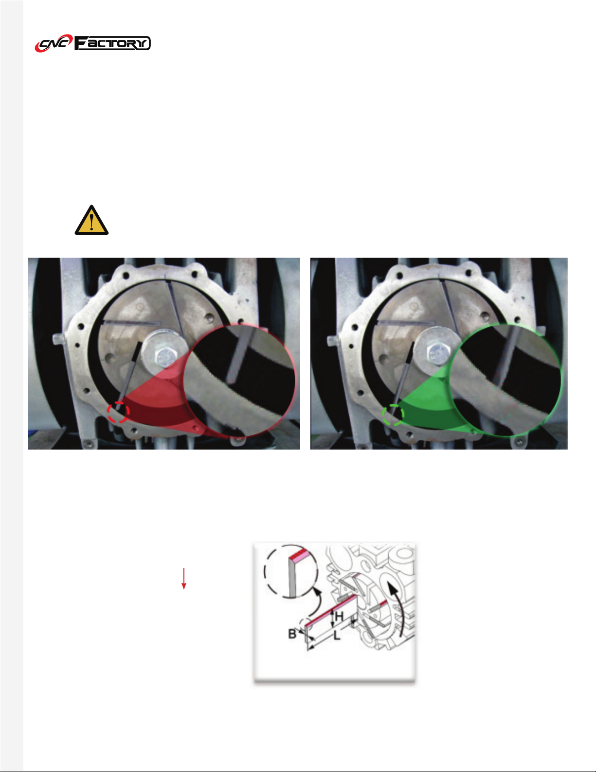
Carbon vanes are installed INCORRECTLY Carbon vanes are installed CORRECTLY
L = 355mm
H = 65mm
B = 5mm
H = 65mm
41mm
The V300 pump uses Rotary Vane Technology to perform robust vacuum pressure. The vanes
should be checked after 3,000 hours of use or at least once a year. Check the width of the blades
(see table for minimum width) to see if they need replacement. Blades will eventually wear out due
to the friction the rotary vanes have with the inner wall.
Annual Cleaning or Vane Replacement
Wear a mask, gloves and safety glasses when cleaning or replacing vanes

User Guide © CNC Factory | Rev04222021
11
V300 SERIES VACUUM PUMP
1. To access the inside, slide open both the rear case
cover (LH) and side case cover (SD). You will need to
remove 8 bolts.
2. Carefully open the belt by unscrewing the next 2
bolts and slowly remove the blades from the rotor.
3. Do not use external force on the rotor while touching
the blade.
4. Make sure it is clean and free from dust and debris.
5. When assembling the blades back, note that the
blade should be 1-2mm from the end of the rotor.
6. Check the oil seal.
7. Clean the grease on the rotor shaft and carefully put
back the cover of the rotor.
8. If the screws do not immediately fit, slightly raise the
cover so the screw hits precisely the center of the
hole. Tighten when it’s locked in.
9. Check if the rotor turns easily.
Table of contents
Popular Water Pump manuals by other brands


Dekker
Dekker Maxima-K 1 Series Installation, operation and maintenance manual

Hydra-Cell
Hydra-Cell T100 Series Installation operation & maintenance

Stryker
Stryker TP600 Service manual

Pentair
Pentair Myers SRM4 Series Installation and operation manual

BUSCH
BUSCH COBRA NC 0630 instruction manual

Champion Pump
Champion Pump CPSE manual