Dekker Maxima-K 1 Series User manual
DEKKER Vacuum Technologies, Inc./Maxima-K/June2007 1
Installation
Operation
and
Maintenance
Manual
Large capacity
liquid ring vacuum pumps
series-1
series-2
series-3
SERIAL NO.:___________________________ June 2007/1
Model Numbers Subject to Change

DEKKER Vacuum Technologies, Inc./Maxima-K/June2007 2
INTRODUCTION
The Maxima-K (series 1, 2 and 3) liquid ring vacuum pump guarantees you improved reliability and reduced
maintenance costs. Compared with other vacuum pumps the Maxima-K water-sealed liquid ring vacuum pump
system offers the advantages of no metal-to-metal contact between the impeller and casing. Grease lubricated
bearings are mounted external to the pumping chamber, isolated by packed gland or mechanical shaft seals.
This means that the pump requires no internal lubrication.
DEKKER pumps and systems have been designed to provide safe and reliable service with low maintenance.
Because a vacuum pump is a rotating piece of equipment, the operator must exercise good judgment and
follow proper safety procedures to avoid damage to the equipment or personal injury. Please review and follow
all instructions in this manual before attempting to install, start or operate equipment.
Safety
All products offered by DEKKER have been designed and manufactured for safe operation. However, the
responsibility for safe operation rests with those who use and maintain these products. Your safety department
should establish a safety program based on OSHA, federal, state and local codes. It is important that due
consideration be given to hazards which arise from the presence of electrical power, hot liquids, toxic gases and
rotating equipment. Proper installation and care of protective devices is essential to safe system operation.
These safety procedures are to be used in conjunction with the instructions contained in this manual.
STORAGE
Keep the pump in a cool dry environment and close the seal fluid isolation valve. Plug all open ports to keep
out dirt and foreign objects. Every 2 - 3 months add a small amount of rust inhibitor into the inlet of the liquid
ring pump and rotate the impeller by rotating the shaft by hand.
If the pump has been idle for more than 2 years, replace the bearing grease before starting up. Use #3 lithium
grease.
After a long idle period, empty the pump completely and remove any scale deposit by using the specially
formulated DEKKER descaling compound Scale-Ex. When the descaling process is complete, add a small
amount of rust inhibitor and rotate the impeller by rotating the shaft by hand. If you cannot rotate the shaft
because the impeller is locked up, contact the factory.
INSTALLATION
The design of the piping system, foundation layout and plant location are the responsibility of the purchaser.
DEKKER Vacuum Technologies, Inc. and its representatives may offer advice but cannot assume responsibility
for operation and installation design.
Please consult an authorized dealer or a specialist skilled in the design of plant layout, system piping design
and foundation design. The installer should carefully read this manual before installing the equipment.
DEKKER or your local dealer can provide start up assistance in most instances at reasonable cost.
Unpacking
Upon receipt of pump or system, immediately inspect for signs of damage. Carefully remove the packing
or crating from around the pump or system. Be sure to keep equipment in the upright position. DEKKER
products are shipped F.O.B. factory, which means that any damage is the responsibility of the carrier and
should be reported to them.
Lifting
Lift the equipment carefully and with weight evenly distributed. DEKKER is not responsible for equipment that
has been damaged through mishandling or dropping.
Location
Install the unit in a well ventilated and dust free area. The pump or system should be a minimum distance of 3
feet from surrounding walls to allow for checking fluid level, temperatures, pressures and general servicing.
Mounting
The pump or system must be installed on a level surface in a horizontal position. The foundation must be
designed to support the total unit weight, without any settlement or crushing, be rigid and substantial enough
to absorb any equipment vibration, maintain true alignment with any drive mechanism, and must permanently
support the baseplate at all points.

DEKKER Vacuum Technologies, Inc./Maxima-K/June2007 3
The vacuum pump system must be leveled and secured with foundation bolts. Foundation bolts must be of
adequate size to withstand the mechanical stresses exerted on it.
All systems should also be grouted into position. The foundation should be constructed to allow for ¾ to 1-½
inch of grout. The baseplate is set on shims and the grout is poured between the foundation and the
baseplate. To have the required body to support the baseplate, grout should be at least ¾ inch thick.
The number and location of shims will be determined by the design of the baseplate. Firm support should be
provided at points where weight will be concentrated at the anchor bolt locations. Use enough, and large
enough shims to provide rigid support. Baseplates are usually designed with openings to allow pouring grout.
When the baseplate has been shimmed and leveled and the anchor bolts have been snugly tightened, a dam
is constructed around the foundation to contain the grout. The dam level should be at least ½ inch above the
top surface of the shims. Grout should be poured inside and around the outside of the baseplate and leveled.
Allow the grout to dry for a minimum of 48 hours before tightening the anchor bolts.
Please note that the pump/motor coupling and V-belt units will need to be realigned prior to start-up,
except with monoblock units.
WORKING PRINCIPLE AND CONSTRUCTION
Working Principle
Liquid ring
Inlet port
Discharge port
Casing
Rotor
The rotor is mounted off-center in a cylindrical pump casing. As the impeller revolves in the direction of the
arrow , the seal liquid forms a liquid ring by centrifugal force. As a result, a half moon shape is developed
between the rings inner face and the rotor hub. When the impeller goes from point A to point B, the pocket
between the two adjacent blades will increase with gas drawn in. When the rotor turns from point C to point A,
the corresponding pocket will reduce from large to small with the previously-drawn gas compressed. When
the pressure is equal to or slightly larger than ambient pressure , the compressed gas will be expelled
through the discharge port.
Seal Liquid
The seal liquid should be fresh, clean water of ambient temperature of neutral pH (soften if necessary). The
seal liquid not only forms a liquid ring, but also dissipates the heat developed by compression and seals the
clearances between the impeller and the port plates.
During operation, the pump has to be continually supplied with fresh water, as part of the seal liquid supplied
is discharged together with the compressed gas.
Use the seal liquid as cool as possible. The seal liquid must not contain solid materials, e.g. sand, otherwise
the casing will be subject to heavy wear or the impeller will jam.

DEKKER Vacuum Technologies, Inc./Maxima-K/June2007 4
Ultimate Suction Pressure (Maxima-K 2 and 3 series only)
For the Maxima-K 2 and 3 series the minimum suction pressure depends on the temperature of the seal
liquid used.
The ultimate suction pressure is down 1”Hg Absolute with the seal liquid and gas at the temperature 60oF and
70oF respectively. Without cavitation protection the suction pressure must not fall below 2.5”Hg Absolute
(ultimate pressure) for continuous operation. If the seal liquid has a higher temperature (higher vapor
pressure), minimum suction pressure is correspondingly higher.
WARNING
Operation of the pump below the minimum permissible suction pressure for a prolonged period of
time can result in the pump being damaged by the cavitation. For high vacuum operation use
cavitation protection.
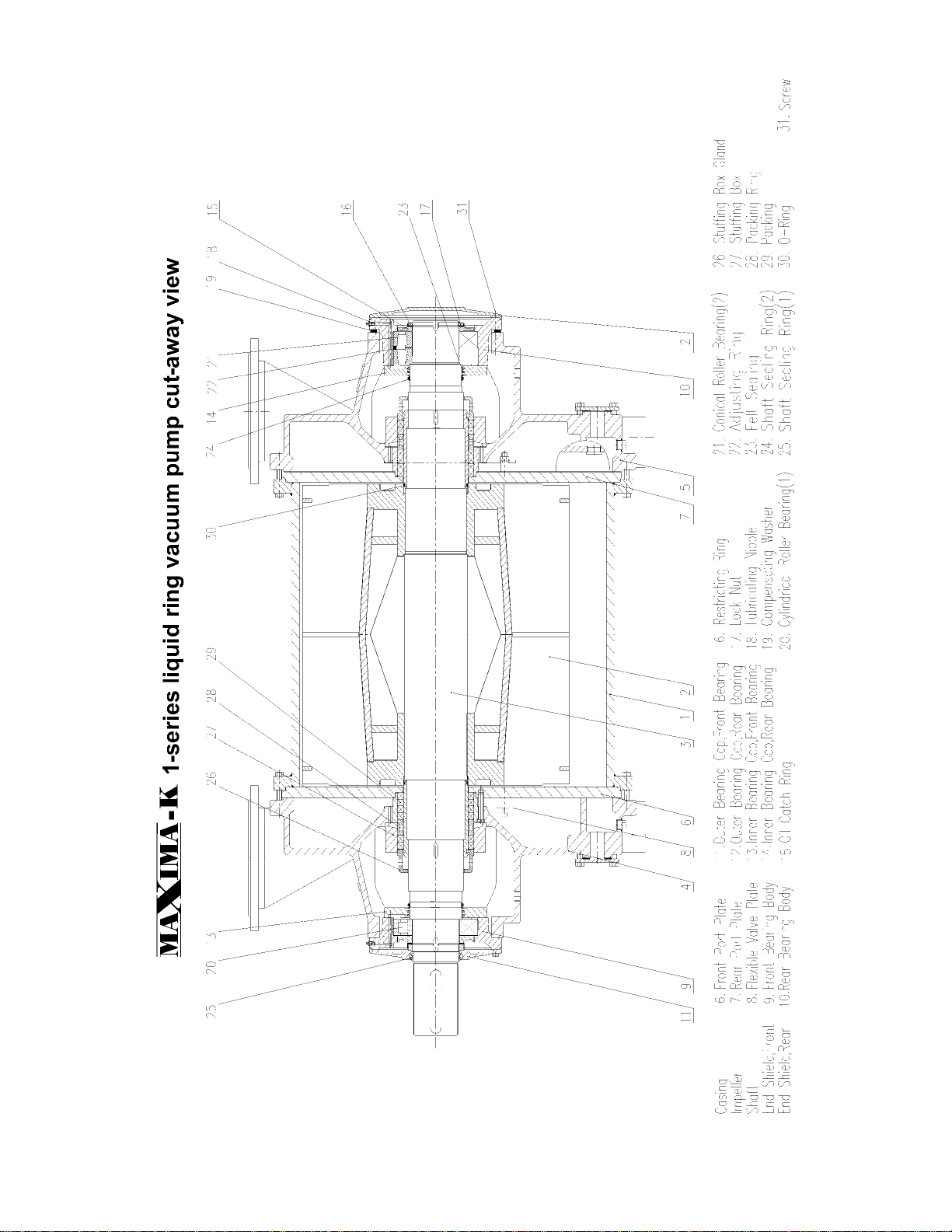
Construction Description
All Maxima-K series pumps consist of the following ten principle components:
(1) Casing
(2) Rotor: of which the impeller and shaft are combined through shrinking process. The shaft is equipped
with shaft sleeves.
(3) Port Plates: the front and rear port plates are bolted to the end housings.
(4) Valve Plate Combination: consisting of a steel plate and a flexible Teflon valve, mounted on the
discharge port of each port plate, allows for the pump to operate at maximum efficiency over the full
vacuum range.. The flexible Teflon valve is a wearing part.
(5) Shaft Seal Assembly: Large-sized pumps usually use packing seals. Mechanical shaft seals are
available as an option. There are two shaft sealing methods for lubrication: internal water supply and
external water supply. The stuffing box is mounted in a direction depending on the shaft sealing method
used. Details as per the following figures.
Internal water supply method for External water supply method for
All Maxima-K series All Maxima-K series
Internal water supply method is indicated External water supply method is indicated
with number 4 cast above the axis with number 4 cast under the axis
Details of specifications of packing as per table below
The pumps are supplied with external water supply as standard.
Maxima-K 1-series
DV4501K-K
DV6000K-K
DV8001K-K
DV9001K-K
DV100001K-K
DV13001K-K
DV18001K-K
(Packing Cross
Section)x circumference
(19X19)X710 mm
(19X19)X820
mm
(19X19)X890
mm
(19X19)X980
mm
Maxima-K
2-series, 3-series
DV2303K-K
DV3503K-K
DV4002K-K
DV4003K-K
DV5002K-K
DV6503K-K
DV7002K-K
DV9003K-K
DV11002K-K
DV13003K-K
DV15002K-K
(Packing Cross
Section)x circumference
(13X13)X530 mm
(16X16)X633
mm
(19X19)X710
mm
(19X19)X820
mm
(19X19)X890
mm
(19X19)X980
mm
DEKKER Vacuum Technologies, Inc./Maxima-K/June2007 5
Note: external water supply is employed with clean water of ambient temperature supplied to shaft
sealing water feed pipe when toxic gases are handled and no seal liquid is allowed to leak from the
shaft seal.
(6) End Shield
(7) Bearings: ball bearings are used for axial shaft loading while the cylindrical roller bearings bear the radial
loads.
(8) Water feed pipes: through which working water is supplied to the pump.
(9) Shaft Sealing Water Feed Pipes: through which cooling and sealing water is supplied to the stuffing box
when external water supply is employed.
(10)Automatic Drain Valve: used to control the water level in the pump at start-up.
For cut-away view of the Maxima-K 1-series, see page 13 at the end of this manual.
For cut-away view of the Maxima-K 2- and 3-series, see page 14 at the end of this manual.
INSTALLATION OF PUMP, MOTOR AND DRIVE
Note: the pumps are subject to strict tests and inspections at the factory before being shipped.
Installation of pump, motor and drives must be carried out by experienced technicians.
The drive variations for all 3 Maxima-K series are either direct, via belt drives or gear reducer.
The mounting methods are:
Direct Drive
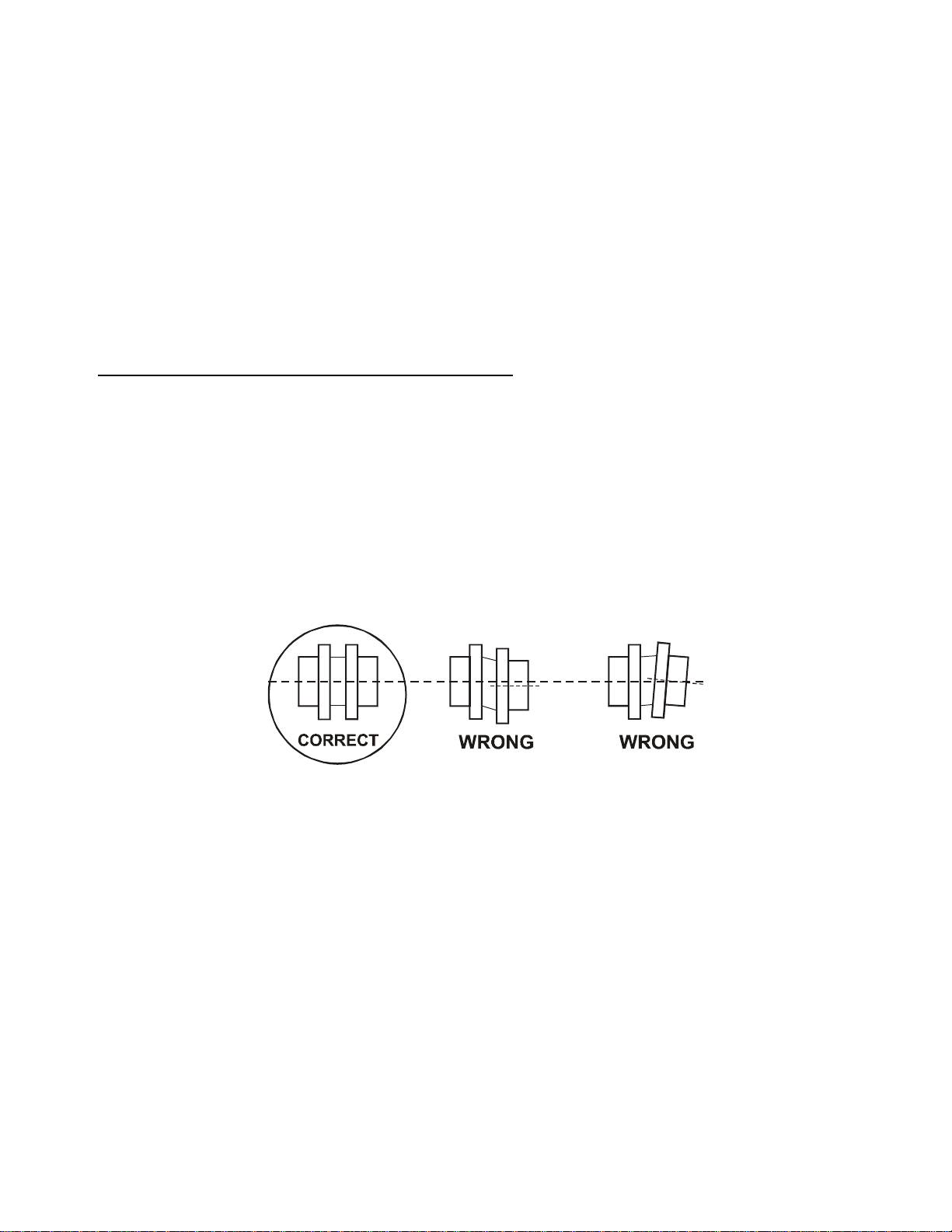
Check drive coupling alignment. Angular alignment should be within .035”- .175”. Parallel alignment should
be within .010” - .025”. Consult the factory for specific system size alignment. Mono-block units do not
require any field adjustment (motors are C-face mounted).
Note: Misalignment may occur during the lifting and handling processes. Re-align the unit if
necessary.
V-Belt Drive
For units utilizing V-belt drives, make sure the sheaves are properly installed and aligned before attempting to
tension the drive. The V-belts should be placed over the sheaves and in the grooves without forcing them
over the sides of the grooves. The tensioning steps 1, 2, 3 and 4 can be used for all types of V-belts, all cross
sections and number of belts and all types of construction.
Avoid excessive heat (140oF and higher); belt life will be shortened. Never switch or mix belts from one
groove to another on the sheaves. Do not use belt dressing. Sheaves should remain free of oil and grease.
When replacing belts install an identical set.
For more specific V-belt tensioning guidelines consult factory.
1. With all belts in their grooves, adjust centers to take up the slack until they are fairly taut. Use standard V-
belt tensioning guidelines.

DEKKER Vacuum Technologies, Inc./Maxima-K/June2007 6
2. Start the drive and continue to adjust until the belts have only a slight bow on the slack side while
operating with load conditions.
3. After several days of operation, the belts will seat themselves in the sheave grooves. Further tensioning
may be necessary to the point that the drive shows a slight bow in the slack side. Insufficient tension is
often evidenced by slipping (squealing) at start-up.
4. If the unit is idle for an extended period of time, the tension on the belts should be removed.
Note: To guarantee safety operation, set on belt guards.
Gear Reducer Drive
If a gear reducer drive is supplied follow manufacturer’s instructions.
ARRANGEMENT AND INSTALLATION OF PIPING
Before installing piping, especially the suction pipe, clear out welding slag, rust and other foreign matter.
When dealing with new pipes, mount a mesh filter screen (20/30 mesh) between pipe and pump flange.
The screen should have a certain amount of extension beyond the circumference of pipe to prevent it from
being sucked into the pump. Clean the screen whenever it is clogged by foreign matter, which will restrict
the gas flow. In general stop the pump to clean the filter once a week until the system inside is clean
enough. After a period of time, it may be removed after making sure that there is no foreign matter
remaining inside.
Note: Use straight piping as much as possible at site. Use piping not smaller in diameter than the
pump connections to prevent higher suction and discharge resistance.
Mount the pressure gauge on the water feed pipe and vacuum gauge on the suction pipe respectively.
Based on the different handling duties, the piping are to be arranged with reference to Figures 5,6,7 on the
next page.

DEKKER Vacuum Technologies, Inc./Maxima-K/June2007 7
1. Pump
6 Compound Gauge
11 Vacuum Gauge
16 Level Indicator
2. discharge Pipe
7 Feed Valve for
Working Water
12 Suction Pipe
17 Check Valve
3. Flush and Drain Gate
Valve
8 Shaft Sealing Water
Feed Pipe
13 Gas and Water
Separator
18 Suction Valve
4. Automatic Drain Valve
9 Shaft Sealing Water
Valve
14 Cylindrical Separator
19 Stuffing Box Drip
5. Working Water Feed
Pipe
10 Pressure Gauge
15 Heat Exchanger
20 Flush and Drain
Connection
Pump Set Arrangement

DEKKER Vacuum Technologies, Inc./Maxima-K/June2007 8
Description of Figure 5
Shows a no recovery, or once-through seal liquid system. This arrangement is preferred when large quantities of seal
liquid are available and no financial advantages are foreseen for re-utilization of the same.
Description of Figure 6
Shows a full-recovery liquid ring vacuum pump systems offering total re-circulation of the seal liquid. In this arrangement
the seal liquid is re-circulated in a closed loop system through a heat exchanger, which removes the heat of compression.
This arrangement is used when corrosive or toxic gases are conveyed.
Description of Figure 7
Shows a liquid ring vacuum pump systems configuration with partial recovery or partial re-circulation of the seal liquid.
This arrangement allows for up to 50% savings of seal liquid. Variations in application and pump models will affect the
amount of seal liquid savings.
Description of Figure 8
Shows a pump installation with floor discharge. The discharge trench should have sufficient flow cross
section, for the seal liquid to discharge by gravity. Mount a check valve on the suction line to prevent back
flow of gas and liquids.
Note: If no circulation of seal liquid is required drain in accordance with the environmental
regulations.
START AND STOP
Preparations before starting
(1) When the pump has been out of operation for a prolonged period of time ( more than two years) , renew
the grease for the bearings of the pump before starting. The grease recommended to use is 3# lithium
grease. Clean the bearings thoroughly with solvent before regreasing.
(2) Flush the pump through the water feed pipes. Turn the rotor by hand to drain the dirty water out through
the discharge line. Before re-starting, two days or more of normal operation, flush the whole piping
system with water to flush out scale and rust.
(4) Check the electrical connections for safety and correctness.
(5) Check the pump for rotation direction, see arrow on pump.
(6) Check the coupling or V-belt alignment.
Start-up
See Figure 5
(1) Open the water feed valve 7 to supply water to the pump (if the pump employs shaft sealing water supply,
open the shaft sealing water valve 9 at the same time). When there is water coming out of the automatic
drain valve 4, shut down water feed valve 7.
(2) Open the suction valve 18.
(3) Start the motor with no water coming from the automatic drain valve 4. When the pump starts running,
open the water feed valve 7 to a point where compound gauge 6 shows pressure. At higher vacuum the
gauge should show between 0 –5” Hg.
(4) In case of external shaft sealing water supply, adjust the shaft sealing water valve 9 to a point where the
water sealing supply pressure gauge 10 shows a reading between 3 –5 psig.
Shut-down
(1) Check if all the corresponding equipment of the pump set has been put into stop mode before stopping
the unit.
(2) Shut down the water feed valve 7 and shaft seal water supply valve 9 (if applicable) and at the same time
shut down the motor.
(3) Open the drain valve 3 to drain water from pump if pump is to be stopped for an extended period of time.
DEKKER Vacuum Technologies, Inc./Maxima-K/June2007 9
OPERATION, SUPERVISION AND MAINTENANCE
During the operation, check the following :
(1) The voltage and the shaft power (current).
(2) The temperature rise of the bearings of the pump. The temperature rise should not exceed 100oF, i.e. the
real working temperature should not be more than 180oF.
(3) Water flow rate of the pump and shaft sealing external water supply if any.
(4) If fitted with V-belt drive check belt tension. New belts are easy to stretch and deform. Stop the unit to
check and adjust 20 minutes after first start-up.
(5) Renew the grease of the bearings every 2500 hour-operation period. The amount of the grease accounts
for 2/3 of the free space of the bearing
(6) If fitted with packed gland stuffing box tighten the packing slightly. Adjust it through the packing gland and
the bolts. There are normally some water drops leaking from the shaft seal. When the packing has been
used too long to be adjusted further, renew it. When renewing, remove the old one, clean the traces of
stuffing box. When mounting the packing, stagger the packing with its cuts at 90°.
(7) Use soft water if possible when water is required as sealing water. If not possible, take away the lime
deposits from the working liquid at appropriate intervals. If the impeller jams after a prolonged standstill
period because of lime deposits, flush with DEKKER descaling compound Scale-Ex and then flush with
clean water. In case of heavy deposits, clean by disassembling the pump
.
ASSEMBLY AND DISASSEMBLY
Disassembly of Maxima-K pumps
For construction, refer to cut-away views on pages 13 and 14 at back of manual.
Separate the pipes and take out the coupling. If belt drive, remove the pulleys.
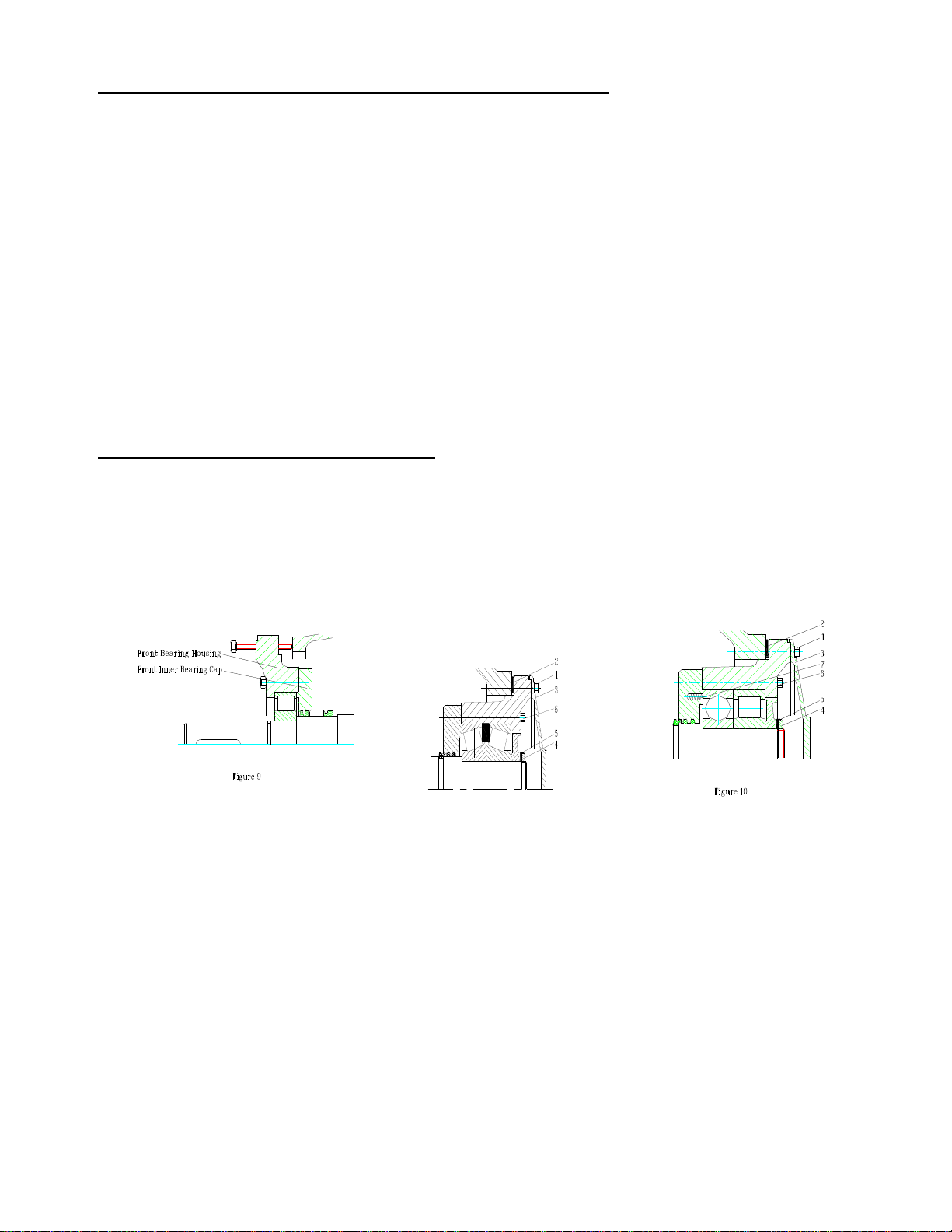
1. Dismantling the Front Bearing
a) dismantle the inner bearing cap 11 and then loosen the lock nuts, stop washer and oil catch ring.
b) Referring to the Figure 9, screw the four M12 screws uniformly to the M12 threaded holes in the front
bearing housing until the front bearing housing and the inner bearing cap are ejected.
Front bearing all series back bearing, 1-series back bearing 2 –and 3-series
2. Dismantling of Back Bearing
Referring to Figure 10
a) Unscrew the screw 1 one by one. Take out carefully each compensating washers set 2 on the screws
with a small thin steel plate. Place different washers on floor with reference to the corresponding
screws and then remove the outer bearing cap 3.
Note: The pumps are supplied with axial clearance set correctly between the impeller and port
plates.
The compensation washers act as adjusting the axial clearance between the impeller and both the
front and rear port plates. When dismantling, care should be taken to distinguish among the
washer sets. Store them separately. Make sure that they shall be re-mounted in their original
places respectively. Otherwise, the front and back axial clearances may be distributed unevenly,
affecting the pump performances or causing the impeller to jam.
b) Remove the lock nut 4 and the stop washer 5.
c) Unscrew the screws 6 tightened evenly and take out the springs 7 distributed uniformly in the inner
bearing cap.
d) Put on the stripping ring (see figure 11) , and then re-screw the screws 6 uniformly.

DEKKER Vacuum Technologies, Inc./Maxima-K/June2007 10
Stripping ring 1-series Stripping ring 2- and 3-series
The Rear Bearing disassembly, such as dismantling bearing housing, inner bearing cap and etc. , is
performed in the same manner of that of the Front Bearing. The ball bearing inner race can not bear the
force without using the stripping ring when disassembly of the bearing. In this case, the bearing will be
damaged. The unit is supplied together with the stripping ring. Customers’ requirements for it are
accepted.
3. Get the pump to stand up vertically across the two blacks with its drive end upward ( see Figure 12).
Dismantle it into pieces part by part . when the present condition limits, the pump may be disassembled
with the whole unit placed horizontally. As a matter of fact, there are some ways to perform the
disassembly. We are ready to provide the corresponding diagrams when the customers request.
4. Because of the bearings of Maxima-K pumps have large magnitude of interference, they may difficult to
remove in the manner stated in Figure 10 and 11. It is recommended that both the front and rear bearing
are to be dismantled to the extent as shown in the figure 13 and 14 and then the bearing inner face will
act as bearing point to enable the bearings to be pressed out. Refer to the reference books for the
methods of disassembly of bearings.
When the back bearing is drawn out with its outer ring bearing force, it will be damaged.
5. It is an important task to examine and clean all the components after the disassembly. According to the
concrete conditions. Carry out the repair, replacement on them or decide whether they are capable of
continuing to work or not.
2 - 3
series
d
D
S
30
125
165
10
35
148
191
10
40
168
223
10
1
series
d
D
S
40
168
223
10

DEKKER Vacuum Technologies, Inc./Maxima-K/June2007 11
Bearings- Check for smooth running. According to the fault and corrosive state, renew them if necessary.
The Front and Rear Port Plates- they are subject to finish turning process when there are some deep
scratch on the faces, which will affect the pump performances.
Shaft Bushing- Renew it based on the wear state.
Impeller- Its face is subject to finish turning process when it has been so worn out to affect the pump
performances. As the difference between the impeller and the pump body in length is the axial clearance,
the two should reduced the same in length through finish turning process.
Assembly of Maxima-K pumps
The assembly of the pump is performed in the reverse manner of the disassembly. In addition to that, attention
should be drawn to the facts that:
1. When the pumps was assembled on a uneven floor, the four pump feet would not remain horizontal like a
plane surface and the clearance between the impeller and the port plates would be reduced with the
impeller jamming after completing the assembly. The correct method is: the pump body is placed on its
bed plate or on a even floor with its end shields mounted on it and then loosen the screws, tighten them
after making sure that the four pump feet are in good touch with the plane surface.
2. Tighten the screws after replacing the compensating washers to their original places, which act as
dominating the distribution of the axial clearance.
3. Adjust the axial clearance again where the rotor is renewed or the finish turning is performed on the
impeller and the port plates.
Adjustment of Axial Clearance
a) Loosen the screws one by one ( See Figure 2).
b) Put a shaft clip on AS end of the shaft.
c) Put a dial meter on the AS end of the shaft.
d) Prize the rotor toward AS with a steel stick to make it be in touch
with the front port plate.
e) Set the meter at zero, prize the rotor toward BS to enable it to be
in touch with the front port plate.
f) The reading shown in the meter is the total axial clearance value ó
of the pump.
g) Replace the compensating washers in their original places. The
washers, made of steel, take three sizes of 0.1mm, 0.2mm and
0.5mm in thickness. All the washers sets are the same in thickness.
h) Secure the screws tightly. At the moment, the meter reads ó/2.
It is likely that he clearance on AS is slightly larger than that on BS.
The minimum clearance on BS should be in conformity with the
requirements specified. Otherwise, paper washers will be added to
both ends of the pump body.
DEKKER Vacuum Technologies, Inc./Maxima-K/June2007 12
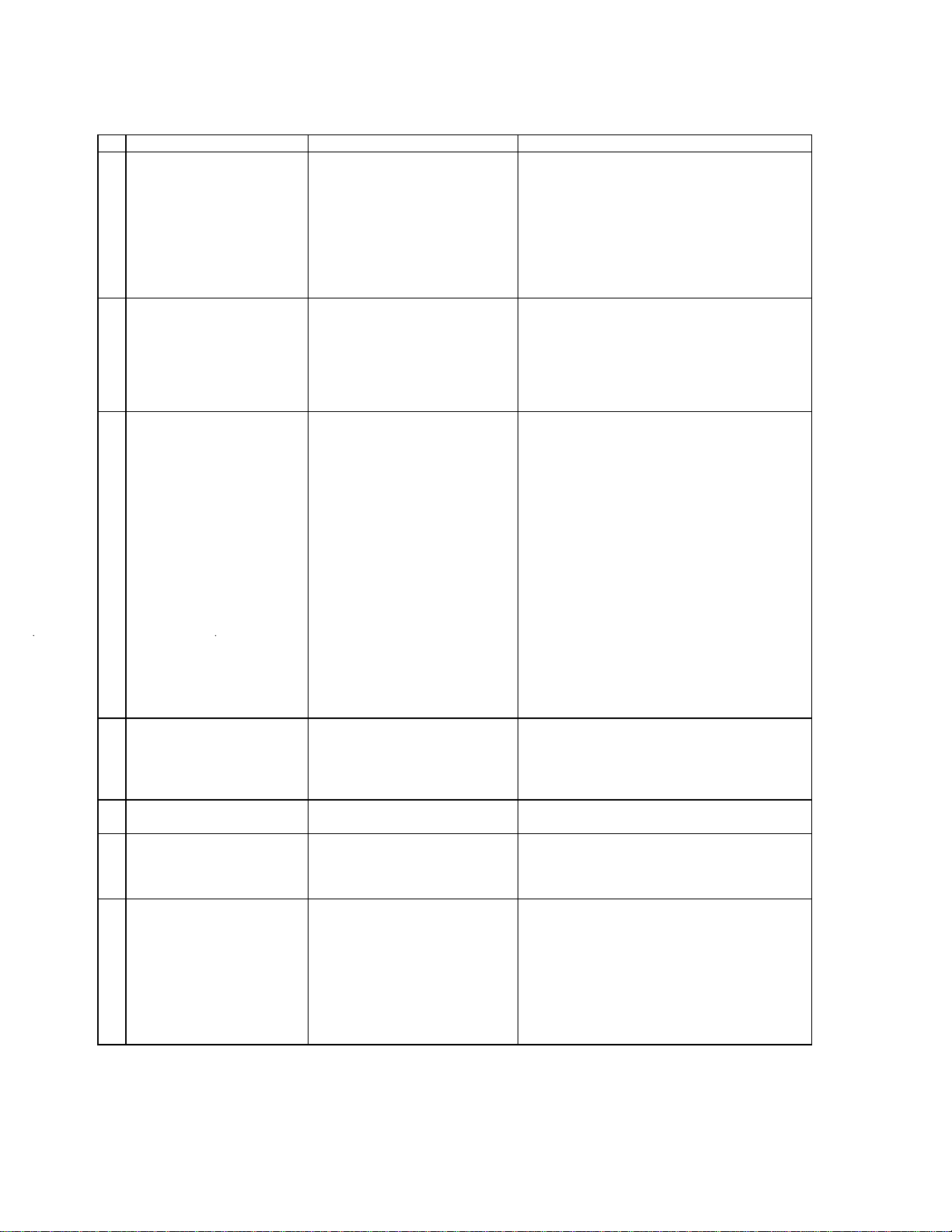
Troubleshooting
Symbols
Causes
Points to check and actions
1.
Difficult in starting,
Motor circuit –breaker trips
or over-heat
1.Water level too high inside
when starting;
2.Packing gland too tight;
3.Belt too tight;
4.Wear developing in pump;
5.Discharge pressure too high;
6.Failure to adjust the current
protection of the electric
cabinet.
1.Start with the water level specified;
2.Loosen the gland adequately;
3.Loosen the belt adequately;
4.Turn the rotor with force and flush with water;
5.Check if the pipes and valves are too small in
diameters;
6.Adjust the thermal relay to the rated current
setting.
2
Jamming during trial or
normal operation
1.Welding slag or other foreign
matters have been drawn in
from new pipes with coming
gas.
2.Heavy lime deposit
1. Loosen both the front and back shrouds, turn
the rotor and flush it with water until it rotate
freely and then secure them. In case of failure,
open it for checking.
2. Dismantle for cleaning or acid washing.
3
Pump capacity low.
Vacuum degree low.
1.Speed low due the belt
slippage;
2.Insufficient water feed or water
too hot;
3.Leakage occurring in the
system;
4.Excessive clearance in the
pump due to excessive
corrosive allowance or
corrosive substance in the
medium;
5.Leaks from packing seal;
6.Heavy lime deposits in pump;
7.Corrosion in pump;
8.Axial clearance not in
conformity with the
requirements after repair;
9.Damage to the flexible valve
plate.
1. Tighten the belt;
2. Adjust the water flow. Check the feed pipes
for clogging;
3. Check the joints for sealing;
4. Clean the medium preventing solids from
entering. Replace the worn parts;
5. Tighten the packing gland;
6. Remove the lime deposits;
7. Replace the parts if necessary;
8. Calibrate the axial clearance.
9. Replace the valve plate.
4
a
Unexpected noise
All series
1.The belt too loose;
2.Gas blowing and ejecting;
3.Suction and discharge pipes’
walls too thin;
1. Tighten the belt;
2. Move the discharge opening to outdoor;
3. Use the pipes with thicker walls;
4
b
Unexpected Noise
2- and 3-series
4.Cavitation occurring when the
pump running under vacuum
4. Use cooler working water or replenish gas in
the suction side; use gas ejector.
5
Excessive vibration
1.The bed plate connected with
foundation badly, the anchor
bolts loose;
2.Misalignment
1.Pour mortar around and under the base plate.
tighten the bolts;
2.Make re-alignment and lock.
6
Bearings overheat
1.Belt too tight ;
2.Misalignment of pump with
motor;
3.Inadequate lubricating, the
grease too dry or too much;
4.Bearings inadequately
mounted;
5.Wear, rust and damage
developing.
1.Loosen the belt adequately;
2.Make re-alignment;
3.Improve the lubricating conditions;
4.Re-mount the bearings.
5.Replace the bearings.
DEKKER Vacuum Technologies, Inc./Maxima-K/June2007 13

DEKKER Vacuum Technologies, Inc./Maxima-K/June2007 14

WARRANTY, REPLACEMENT & RETURN POLICIES (Page 1)
DKR_KNOW_GEN_09_rev2
Warranty policy for DEKKER vacuum pumps, systems and/or compressors (hereafter referred to as the
Product)
DEKKER Vacuum Technologies, Inc. (hereafter referred to as DEKKER) warrants that the products hereunder
shall be free of defects in material and workmanship and conform to the specifications given in connection with the
sale of the product.
DEKKER warranty is from date of shipment, provided the DEKKER Products have been operated exclusively with
DEKKER seal fluid (where noted) and have been operated during the full warranty period as per the instructions
given in the Installation, Operation, and Maintenance (IOM) Manual. If purchaser elects to use a non-DEKKER seal
fluid, which has been approved by DEKKER, product warranty may be reduced (as noted below). If purchaser
elects to use a non-DEKKER seal fluid, which has NOT been approved by DEKKER, product warranty may be
void.
3-Year Warranty
Vmax systems: 3-year warranty with DEKKER Vmaxol seal fluid; 2-year warranty with non-DEKKER seal
fluid
HullVac pumps and systems: 3-year warranty with DEKKER HullVac seal fluid; 2-year warranty with non-
DEKKER
seal fluid
2-Year Warranty
DuraVane pumps, systems and compressors: 2-year warranty with DEKKER Duratex seal fluid;
18-month warranty with non-DEKKER seal fluid
TiTan liquid ring vacuum pumps and compressors: 2-year warranty
Maxima-C and Maxima-K liquid ring vacuum pumps: 2-year warranty
AquaSeal systems: 2-year warranty
ChemSeal systems: 2-year warranty
1-Year Warranty
VmaxMTH systems: 1-year warranty with DEKKER Vmaxol seal fluid; 1-year warranty with non-DEKKER seal
fluid
All other systems not specified above: 1-year warranty
All custom-engineered systems: 1-year warranty
6-Month Warranty
Rebuilt pumps and systems: 6-month warranty
Ninety (90) Days
Mechanical shaft seals: Ninety (90) day warranty
All 3rd party components are subject to Manufacturers’ Warranty.
15

WARRANTY, REPLACEMENT & RETURN POLICIES (Page 2)
DKR_KNOW_GEN_09_rev2
The replacement of maintenance items including, but not limited to oil, seals, bearings, filters, vanes in rotary
vane pumps, etc., made in connection with normal maintenance service are not covered under this warranty.
No warranty shall apply to products that have been misused or neglected, which includes operation in excessive
ambient temperatures, dirty environments or the pumping of corrosive, erosive or explosive liquids or gasses or
for problems caused by a build-up of material on the internal parts of the product.
Under this warranty the purchaser is entitled to the repair or replacement (whichever DEKKER elects) of any part
or parts of the product which do not conform to specifications. This warranty shall be void unless said
nonconformance is discovered before the expiration of this warranty. For repairs, DEKKER must be notified in
writing, a Return Merchandise Authorization (RMA) must be obtained and the nonconforming part(s) need to be
returned to DEKKER, transport charges prepaid, within thirty (30) days of discovery. Repairs shall be made at
DEKKER’s facility without charge, except for return transport charges. Replacement parts provided under the
terms of this warranty are warranted for the remainder of the
warranty period applicable to the product in which they are installed, as if such parts were original components of
that product.
No allowance will be granted for repairs or alterations made by the purchaser without the DEKKER’s written
consent.
In lieu of the foregoing remedy, DEKKER may (if DEKKER so elects), redesign and/or replace the product or
refund the full purchase price thereof.
If purchaser disassembles the product for any reason without the written consent of DEKKER, this warranty shall
be void.
Limitation of liability for DEKKER vacuum pumps, systems and compressors:
DEKKER’s obligations are limited to repair, redesign, replacement or refund of the purchase price, at DEKKER’s
option. In no event shall the purchaser be entitled to recover incidental, special or consequential damages arising
out of any defect, failure or malfunction of the product.
This warranty and DEKKER’s obligation there under is expressly in lieu of all other warranties, including but not
limited to the implied warranties of merchantability and fitness for a particular purpose. All warranties which
exceed the aforementioned obligations are hereby disclaimed by DEKKER and excluded from this warranty. No
other person is authorized to give any other warranty or to assume any other liability on DEKKER’s behalf without
written authorization.
Replacement Policy (Product Failure) for DEKKER vacuum pumps, systems and/or compressors
(hereafter referred to as the Product)
DEKKER Product failures must be reported directly to DEKKER immediately. Product must be returned to
DEKKER factory for warranty consideration, unless field service is Pre-Authorized by DEKKER. The product
will be evaluated for defects in workmanship and materials. Under no circumstance will product be considered
for immediate, no-charge replacement without substantial evidence of material defect or assembly error.
User error, incorrect supply voltage, or damage incurred as a result of mishandling will not be honored.
16

WARRANTY, REPLACEMENT & RETURN POLICIES (Page 3)
DKR_KNOW_GEN_09_rev2
Product failures will require a purchase order (in the original dollar amount of damaged/failed product) from the
distributor or direct customer to release the replacement pump or product. A Return Merchandise Authorization
(RMA) number will be generated by a DEKKER After Sales Associate and issued to the distributor or customer to
return the original product. The product will undergo a thorough evaluation upon receipt and credit will be issued
in full if the failure is determined to be warrantable. If failure is determined not to be warrantable, the purchase
order will be charged for the replacement product.
DEKKER does not cover expedited shipping in any circumstance.
Motor failures will be determined warrantable based on the evaluation of the motor manufacturer or their
authorized representative. Please contact DEKKER for assistance with finding your motor manufacturer’s local
authorized repair center.
Return Policy for DEKKER vacuum pumps, systems and/or compressors (hereafter referred to as the
Product)
Return for Credit (product not needed):
Distributor or direct customer will request an RMA number from DEKKER After Sales Associate and return
the product pre-paid. Collect freight or parcels will be refused unless prior approval is given by After Sales
Associate.
A minimum 15% restock fee applies. If product is damaged by customer, as a result of mishandling or poor
packaging for return shipment, this fee may be increased as determined by DEKKER.
Return for Replacement (incorrect part number received due to DEKKER shipping error):
New purchase order is required to release correct items. DEKKER After Sales Associate will issue RMA for
incorrect items. Upon receipt, if product is returned in good condition, the original order will be credited in
full.
Return for Replacement (customer ordered incorrect part):
New purchase order is required to release correct items. DEKKER After Sales Associate will issue RMA for
incorrect items. Upon receipt, original order will be credited less minimum 15% restock fee. If product is
damaged by customer, as a result of mishandling or poor packaging for return shipment, this fee may be
increased as determined by DEKKER.
Return for Replacement (damaged product received):
Photos should be taken immediately upon discovery of damage to assist in a claim with the shipping company.
A new purchase order is required to release replacement items. Once items are received at DEKKER, they
will be evaluated for repair/replacement and liability determined with shipping company. It is the discretion of
the receiver to refuse any shipment. If you have any questions or concerns, contact a DEKKER After Sales
Associate.
17
This manual suits for next models
20
Table of contents
Other Dekker Water Pump manuals


Popular Water Pump manuals by other brands


Aspen
Aspen mini orange manual

YAMADA
YAMADA DR-50B1SUS instructions

ITT
ITT Goulds Pumps 3175 Installation, operation and maintenance instructions

Hayward
Hayward TriStar SP3200 Series owner's guide

Ingersoll-Rand
Ingersoll-Rand ARO WLM2203A 2 Series Operator's manual

teel
teel 4RJ47 Operating instructions & parts manual

Nordic
Nordic AP-L0218 operating manual

Interpump Group
Interpump Group Pratissoli WK Series Repair manual

Raider
Raider RD-WP800S instruction manual

Nordson
Nordson BM 200 Operator card

WOERNER
WOERNER GMG-K Translation of the original operation manual

Grundfos
Grundfos DME series Installation and operating instructions