Co-Fastening CSF00490 User manual

Oil Free Silent
Air Compressor
Instruction Manual
Co-Fastening CSF00490 & CSF20240

Field Service Manual FSM
Page
Introduction………………………………..…………………………...……………………………………4
Safety First………………….……………………………………………………………………………….5
Exploded View and Parts List…………………………...………..…………………………………………6
Preventive Maintenance and Troubleshooting Guide…….…………….………………………………….9-10
Required Tools and Materials……………..………………………………………………………………..11
Component Repair…………………………………………..……………………………………………...11
Servicing the Head or ValveAssembly…………………….………………………………………………11
Servicing the connecting Rod Assembly and Eccentric Assembly……..………………………………….16
Reassembling the Compressor…………………….……………………………………………………….20
Table of Contents

1
This Field Service Manual is intended for use ONLY by an authorized service center and properly trained and
experienced repair personnel. Who employed by the authorized service center. THIS SERVICE MANUAL SHOULD NOT
BE USED OR DISTRIBUTED TO THEPUBLIC.
THE INSTRUCTIONS AND WARNINGS HEREIN PRESUME EXISTING FAMILIARITY WITH THE DESIGN
AND FUNCTION OF THESE AND SIMILAR PRODUCTS.AND THEIR COMPONENTS.
Please Note:
The model(s) represented in this manual may have additions and/or modifications made at any time. Pictures
represent a standard unit series and an actual unit may vary slightly. This manual is based on the latest products′
information available at the time of creation or last revision. It is believed to be generally accurate and reliable. Consult the
factory if detailed in formation is desired, or. Whenever there is a question about a given unit’s configuration or
performance specifications.
Introduction

It is recommended that you thoroughly read and understand this manual before you attempt to service the GSE series
of compressors to which this applies. PLEASE NOTE THE FOLLOWING CAUTIONS AND WARNINGS FOR
YOUR OWNSFETY.
Caution
To avoidpersonal injury and/orproperty damage, only authorized service personnel should service this unit.
Warning
.To avoid the risk of electrical shock, personal injury, or death, disconnect power before servicing this unit
Caution
To avoid personal injury, do not remove fan guards while unit is connected to power.
Caution
To avoid personal injury, especially to eyes and face, use eye and face protection when servicing this unit.
Caution
people in the area. Unit is capable of pressures of 600kPa.
To avoid personal injury, especially to eyes and face, never point the exhaust airflow at yourself or other
Caution
d te any component in your compressor.All moving parts are permanently lubricated.To avoi damage, never lubrica
Caution
To avoid damage or personal injury, always try rotating the fan by HAND prior to connecting the unit to the power
source. Check for suction at the air inlet port by placing your finger over the port and you turn the fan. You should
feel a slight suction with each rotation of the fan .If you don’t feel suction, or if you feel or hear a thump as you turn
the fan, DO NOT CONNECT THE UNIT TO A POWER SOURCE Review the assembly procedure for possible error.
2
!
!
!
!
!
!
!
Safety First

3
Exploded View and Parts List
Model No: TAT0704HP
3
NO. DESC. SPEC. UNIT QTY.
1 OIL FREE AIR PUMP&MOTOR 230V/50Hz/400W/4POLE pcs 1
2 AIR FILTER pcs 1
3 ELBOW G1/4 pcs 1
4 SHOCK PAD M6 pcs 4
5 PRESSURE SWITCH pcs 1
6 CONNECTION G3/8-G1/4 pcs 1
7 SAFETY VALVE CE8.8kg pcs 1
8 CHECK VALVE G3/8 pcs 1
9 CAPACITOR SHELL pcs 1
10 CAPACITOR pcs 1
11 EXHAUST PIPE pcs 1
12 RELIEF PIPE pcs 1
13 TANK pcs 1
14 RUBBER FOOT M6 pcs 4
15 HOSE ELBOW G1/4Xφ10 pcs 2
16 CONNECTION HOSE φ10 pcs 1
17 PRESSURE GAUGE φ50 pcs 2
18 QUICK COUPLER pcs 1
19 REGULATOR pcs 1
20 POWERCORD VDE 16A 10METER WITH PLUG pcs 1
21 DRAIN VALVE G1/4 pcs 1
CSF00490

4
Model No: TAT0704HP
Item No. Part No. Qty. Per Amply Qty. Per Unit Description
1 040300
040303
M5×8
040301
040604
040501
040502
010506
M5×20
040100
040103
040109
070102
040101
010105
470107
040607
040608
—Connecting Rod, Eccentric & Bearing Assembly
2 1 Piston Cup
3 1 Screw-Piston Cup Retainer
4 1 Piston Cup Retainer
5 1 Cylinder Sleeve
6 — Left Head/Right Head
7 — O-Ring-Head Gasket
8 — Screw-Head
9 — Valve Plate Assembly
10 1 Valve Restraint
11 2 Valve Keeper Strip
12 2 Valve Flapper-Intake & Exhaust
13 1 Valve Plate
14 2 Screw-Valve Flapper
15 — O-Ring Valve Flapper
16 — Left Fan
17 —
2
2
2
2
2
1
2
12
2
2
4
4
2
4
2
1
1 Right Fan
CSF00490

5
Model No: TAT-2520P
CSF20240

6
Model No: TAT-2520P
NO. DESC. SPEC. UNIT QTY.
1 TANK 20L pcs 1
2 OIL FREE AIR PUMP & MOTOR 230V/50HZ/1500W/4POLE pcs 1
3 CAPACITOR SHELL pcs 1
4 CAPACITOR pcs 1
5 WHEEL 8" SOLID RUBBER WHEEL pcs 2
6 wheel shaft M14 pcs 2
7 SCREW M8*30 pcs 2
8 RUBBER FOOT φ8 pcs 2
9 DRAIN COCK G1/4 AIR COCK pcs 1
10 PRESSURE GAUGE 50 pcs 2
11 REGULATOR pcs 1
12 QUICK COUPLER pcs 2
13 PANEL pcs 1
14 SCREW M5X16 pcs 6
15 HANDLE SLEEVE φ32x120 pcs 3
16 CONNECTOR G3/8-G1/4 pcs 1
17 SAFETY VALVE CE 10kg pcs 1
18 PRESSURE SWITCH 7.5-9.5kg pcs 1
19 PANEL FOR TOOLS pcs 1
20 SCREW M5X16 pcs 4
21 PRESSURE BAR pcs 1
22 SPRING pcs 2
23 SCREW GROUP M4X20 pcs 2
24 HANDLE pcs 1
25 SCREW GROUP M10X50 pcs 2
26 POWERCORD VDE 16A 10METERS pcs 1
27 RELIEF PIPE pcs 1
28 EXHAUST PIPE pcs 1
29 CHECK VALVE PT3/8 pcs 1
30 SOLENOID VALVE 230V/50Hz pcs 1
31 RUBBER FOOT φ6 pcs 2
32 SCREW M6X30 pcs 2
33 AIR FILTER pcs 2
34 SHOCK PAD pcs 4
35 HOSE COUPLING G1/4Xφ10 pcs 2
36 CONNECTION HOSE φ10 pcs 1
CSF20240

7
Model No: TAT-2520P
Item No. Part No. Qty. Per Amply Qty. Per Unit Description
1 040300
040303
M5×8
040301
040604
040501
040502
010506
M5×20
040100
040103
040109
070102
040101
010105
470107
040607
040608
—Connecting Rod, Eccentric & Bearing Assembly
2 1 Piston Cup
3 1 Screw-Piston Cup Retainer
4 1 Piston Cup Retainer
5 1 Cylinder Sleeve
6 — Left Head/Right Head
7 — O-Ring-Head Gasket
8 — Screw-Head
9 — Valve Plate Assembly
10 1 Valve Restraint
11 2 Valve Keeper Strip
12 2 Valve Flapper-Intake & Exhaust
13 1 Valve Plate
14 2 Screw-Valve Flapper
15 — O-Ring Valve Flapper
16 — Left Fan
17 —
2
2
2
2
2
1
2
12
2
2
4
4
2
4
2
1
1 Right Fan
CSF20240

8
Preventive Maintenance and Troubleshooting Guide
GSE®recommends that you perform the following service to minimize unexpected downtime for your
compressor:
Replace the connecting rods or piston cups and sleeves
Replace the flapper valves
Replace the head O-ring Head gasket.
Replace the valve plate O-rings
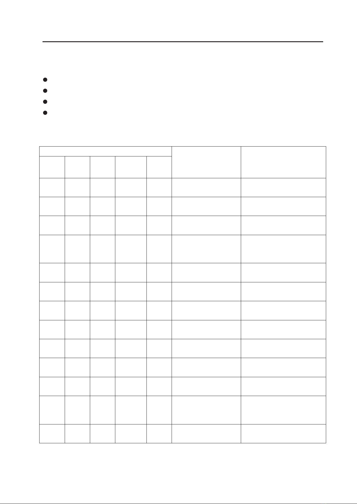
If you are having a problem with your compressor, use this table to help determine the cause(s):
Problem
Low
Flow Low
Pressure Unit Will
Not Start Motor ①
Overheats Loud
Unit
Possible Cause Corrective Action
×High voltage at compressor Reduce voltage
× × × × Low voltage at compressor Increase voltage
× × × Damaged valves Replace flapper valves
× × × Debris in valves Remove debris and check for valve
damage
× × × Damaged gaskets Replace gaskets
× × × Worn Cup Replace connecting rod
× × × Loose head screws Tighten head screws
×Broken fan Replace fan
× × × Bent motor shaft Replace entire unit
× × Damaged capacitor Replace capacitor
×Loose fittings Tighten fittings
× × Insufficient ventilation in
enclosure
Increase air circulation to enclosure
× × Worn bearings Replace Eccentric Bearing assembly
①Thermal protector in motor will interrupt current when motor overheats.

9
To disassemble and reassemble your compressor, you need the following tools and materials:
Torque wrench that has an N.m scale (for head screws, connecting rod, flapper valve screw, and pipe plugs).
RTD500CN driver (for head screws).
S3 Allen wrench attachment for torque wrench (for eccentric screw).
‘+’ like attachment for torque wrench (for flapper valve screw).
screwdriver (for retainer screws).
Soft, clean cloths.
Compressor
Housing
Capacitor LEAD END
Capacitor LEAD SID Compressor
Reference Drawing: Technology to assist with the following instructions.
Required tools and Materials

10
Component Repair
Servicing the Head, Valve Plate Assembly and Connecting Rod and Bearing Assembly
The head would only needto bereplaced if it is
visibly damaged.
Component Parts Required
You will need:
Head (if damaged)
Head gasket
Valve plate O-ring
Complete valve plate assembly or individual flapper
valves.
Flapper valve screw(s) if replacing individual flapper valve(s).
Removing the Head
1、Disconnect the power.
2、Disconnect all airlines and remove compressor from the enclosure.
3、Remove all screws (1) that fasten the head (2) to the compressor housing.
!
Attention
If you are replacing the head and gaskets only,
see the assembly instructions on page21. To
replace the Valve flappers and connecting rod
assembly, continue to page 12、16.
!
4、Carefully separate the head from the compressor body.
5、Carefully separate the valve plate assemblies (4) from the heads.
6、Remove the head gasket O-rings (3) and replace.
7、Turn the valve plates over and replace the valve plate gasket O-rings (5).

11
Removing the Flapper Valves
Opposite LEAD Side
1234
Note: We recommend you remove and replace one flapper
valve at a time. This will help to simplify the repair
process and orient the flapper valve correctly in the
valve plate.
1、
If you are replacing a flapper valve on the topside of
the valve plate (side facing the head), remove the flapper
valve screw (1), with a ‘+’ like screwdriver. Lift off the
valve keeper strip (2), lift off the strengthen valve (3), and
lift off the flapper valve. (4).
1
Opposite LEAD Side
Port1
Port2
2、
alcohol. (
Remove any debris from the valve plate with water-free,
Soaps and detergents should not be used due to
the potential for corrosion from soap residue.)
3、Place the valve plate on the compressor housing and
orient it as illustrated. Make sure the O-ring head gasket
towards the cylinder. Note the orientation of the valve
ports.
4、Orient a new flapper valve (1) over Port 1. Observe the
location of at the end of the flapper valve.
5、Place a valve restraint (3) over the flapper valve.
Radium
6、Place a valve keeper strip (4) over the valve restraint
observing that the Restraint’s Radium is facing Valve
plate and oriented as shown in the illustration.
7、Line up the screw holes in all of the valve
components and fix the screw on the valve plate.
8、Make sure the flapper valve is centered over the port
of the valve plate and that all of the other components
line up with the flapper valve.
Caution:
Do not over tighten the flapper valve screw or it will
shear off in the valve plate.
!
9、Tighten the flapper valve screw to 1.3N.m. Using a torque wrench with a ‘+’ like attachment.

12
LEAD Side Port1
Port2 1
2
3
1、If you are replacing a flapper valve on the bottom
side of the valve plate (side facing the compressor
housing), remove the flapper valve screw (1) with a ‘+’
like driver, lift off the valve keeper strip (2).
2、Clean any debris with a soft, damp cloth. Turn the
compressor head upside down and place the valve plate
on the compressor head and orient it as illustrated.
Note the position of the valve ports and the location of
the power leads on the compressor housing.
2
1
LEAD Side
3、Orient a flapper valve (1) over Port 2. Observe the
location of the notches (2) at the end of the flapper
valve.
4、
Place a valve keeper strip (3) over the flapper valve,
observing that the radius the valve plate, and oriented as
shown in the illustration.
5、
Line up the screw holes in all of the valve components
and fix them upon the flapper valve screw by screws.
6、
Make sure the flapper valve is centered over the Port and
that the valve keeper strip lines up with the flapper valve.
43
Caution:
Do not over tighten the flapper valve screw or it
will shear off in the valve plate.
!
7、Tighten the flapper valve screw to 1.4N.m.
Using a torque wrench with a ‘+’ like attachment.
Attention:
If you are only replacing the valve flappers, see
the assembly instructions on page 12.
If you are replacing the cup and sleeve turn to
the Rebuilding Connecting Rod Assemblies
Section found on page 18.
!

13
Servicing the Connecting Rod Assembly and Eccentric Assembly
Refer to the Preventive Maintenance and Troubleshooting
Guide in this manual to determine whether a complete
connecting rod assembly. Or it’s component parts, or an
eccentric needs to be serviced.
Component Parts Required
You Will need:
Connecting rod assembly (ices) or piston cups and
sleeves.
Valve plate gasket O-ring (s).
Head gasket O-ring (s) (if defective).
Removing the Connecting Rod Assembly
and Eccentric
NOTE: ONLY REMOVE ONE CONNECTING
ROD ASSEMBLYAT A TIME.
1、
Carefully remove the fan by pulling it straight off the
motor shaft. Do not pull the fan blades.
Eccentric
Eccentric Set Scrow
AccessHole
2、Turn the motor shaft to align the eccentric setscrew,
the connecting rod screw separately and with the hole of
the housing. (See illustration for location of access hole).
3、Slide the eccentric bearing assembly straight off the
shaft.
4、Slide and rotation the connecting rod, remove it from
the housing.

14
Rebuilding Connecting Rod Assemblies
If you are rebuilding the connecting rod assembly using
component parts, follow this procedure:
When replacing the piston cup (4), be sure to replace
the sleeve (1) at the same time, Place the connecting
rod in a fixture before attempting to remove the
retainer screw. Heat will help to dissolve the loc tile
bond.
(1) Remove the retainer screw (2) from the cup
retainer.
(2) Remove the retainer (3) from the connecting
rod.
(3) Remove the cup (4) and discard.
(4) Place the new piston cup (4) on the connecting rod.
(5) Place a piston cup retainer (3) on the cup/connecting
making sure the boss of the retainer is seated in the
pilot of the rod.
(6) Insert the retainer screw (2) into the connecting rod (5) and tighten to 3.0 N.m.
Note:
Both Connecting Rods showntor orlentation,
DO NOT remove both at once.
Assembly of the Connecting Rod to
the Compressor
1、Put cylinder sleeve into trough of housing keeper
and make connecting rod being vertical. Note
connecting rod screw to face to housing.
2、Replace eccentric into the shaft and insert bearing into
connecting-rod bearing. Rotate eccentric to line up
setscrew with access hole in bottom of housing. Move
main shaft, let shaft flat and eccentric screen hole
vertically. Tighten screw to 4N.m.
Set Screw Access Hole
3、Rotate shafe with connecting rod moving up and down.
Connecting rod can move with out any obstacle at this
moment. Then use an Allen to tighten connecting rod
screw.
Note: Both connecting rod assomblies shown for orientation.
Do NOT remove both at once.
Attention:
Do not damage the piston cup (4) when you remove the connecting rod assembly
from the compressor housing. If the cup is damaged, you must replace it.
!
To replace the connecting rod and bearing
assembly continue to page 19.
Attention:
!

15
Reassembling the Compressor
After the connecting rod assembly and eccentric are
correctly assembled, you can assemble the valve plates and
bead to the compressor.
O-ring Groove
Bottom of Valve Plate
Power Leads
1、Insert the valve plate gasket O-ring into the O-ring
groove located on the bottom of the valve plate.
2、Position the compressor housing as shown in the
illustration. Notice the orientation of the power leads.
Note: Make sure that the connecting rod sleeves
are seated against the compressor housing.
3、Observe the orientation of the valve plate
assemblies. Place them on the compressor
housing as shown.
Tab Tab
Compressor Housing
Valve Plate
4、Inset two new head gasket O-ring into the
groove located on the bottom of the Head.
Note: Ensure the valve plate is properly
engaged to housing locators.
Note: Ensure that O-Rings are fully
assembled in grooves and not pinched.
Botto m of the Head
O-ring Gasket
Caution:
To prevent damage to the compressor,
never apply any sealant or lubrication
to the O-rings.
!

16
5、Place the head on the valve plate assemblies
observing the position of the air intake and exhaust
ports.
Note: Make sure the head gasket O-rings are
not pinched.
6、Insert the head screws and tighten strainly each
screw until it is snug. Use 3.5N.m in a drive to
tighten each head screw.
Opposite Lead Side
Intake
Servicing the Fan
If one or both have the fans break use the following procedure:
!
Caution:
To avoid property damage or personal
injury, always try rotating the fan by HAND,
prior to connecting the unit to the power
source. Check for suction at the air inlet
port by placing your finger over the port
as you turn the fan. You should feel a slight
suction with each rotation of the fan. If
you donÿ t feel suction, or if you feel or
hear a thump as you turn the fan, DO NOT
CONNECT THE UNIT TO A POWER SOURCE; review
the assembly procedure for possible error.
!
Clip Toward Compressor
Flat
1、Carefully remove the fan by pulling it straight off the motor shaft.
2、Aligntheflaton themotorshaftwiththeflatonthefanand slidethe fanbackonto themotorshaft,makingsurethefanclip(1) facesasshown.
Exhaust
Numbers indicate tighterming sequence
Clip Toward Compressor
Co-Fastening BV * Televisieweg 131 1322BE Almere * 036-200 22 36 * www.co-fastening.nl
This manual suits for next models
1
Table of contents
Popular Air Compressor manuals by other brands

Vector
Vector VEC270MG Owner's manual & warranty

Wolpertech
Wolpertech WT-335/10/50 Translation of the original instructions

Samson
Samson S-com plus owner's manual

Stealth
Stealth SAUQ-1105 Operator's manual

Pattfield Ergo Tools
Pattfield Ergo Tools PE-1506 Original instructions

ABB
ABB TPX Series Assembly instructions