Gas Connection 8mm OD Tubing
Ignition - Piezo Spark Generator
Appliance Weight 63.5 kg
The Coalbrookdale GS1i is factory set to operate on
natural gas or propane (See data label) and is available
with a standard or traditional door option.
Due to newness the stove may give off a slight smell for
a short period after commissioning. This is quite normal
and will disappear after a few hours operation, open
windows and doors if required.
The Coalbrookdale GS1i has one access door as part of its
design. The glass fronted door is for access to the coals
and apart from initial commissioning of the stove, or in
case the pilot is required to be lit with a taper due to
malfunction of the spark ignition system. UNDER NO
CIRCUMSTANCES MUST THE STOVE BE OPERATED
WITH THIS DOOR OPEN OR IF THE GLASS IS CRACKED
OR BROKEN.
The Coalbrookdale GS1i has been designed similar to a
solid fuel stove to relevant safety standards, but during
use, many parts of the appliance can become HOT to
touch. We recommend that you provide and secure a
fireguard complying with BS 6539 when the room is used
by elderly, infirm or young persons.
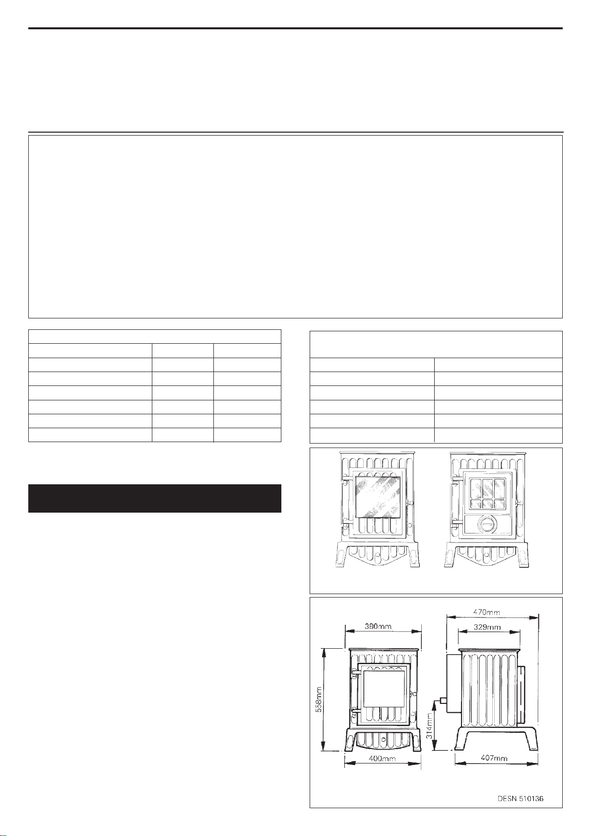
Note: The illustrations show the appliance fitted with the
standard door option.
8/00 EINS 510878
Installation
and
Servicing
Instructions
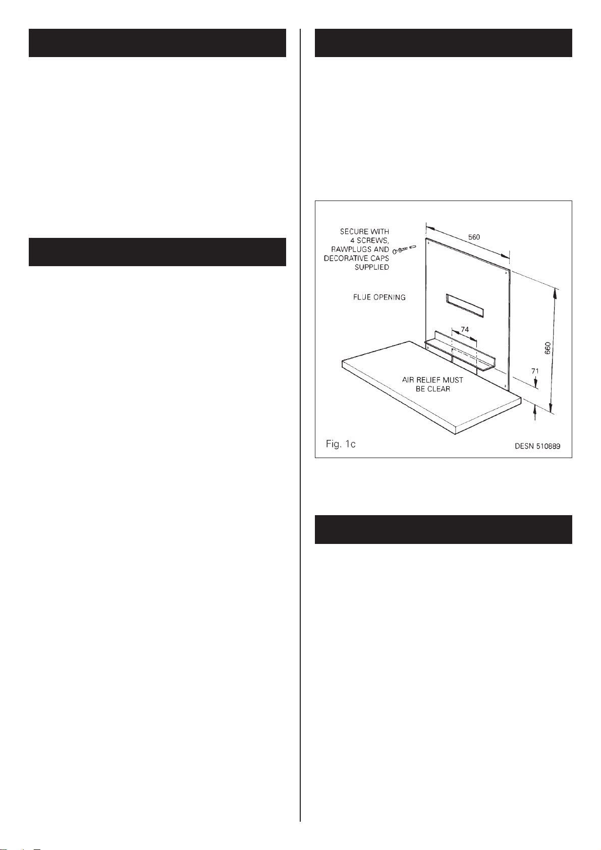
Closure Plate Model
Consumer Protection Act 1987
As manufacturers and suppliers of cooking and heating products, in
compliance with Section 10 of the Consumer Protection Act 1987,
we take every care to ensure, as far as is reasonably practicable, that
these products are so designed and constructed as to meet the
general safety requirement when properly used and installed. To this
end, our products are thoroughly tested and examined before
despatch.
IMPORTANT NOTICE: Any alteration that is not approved by Aga-Rayburn,
could invalidate the approval of the appliance, operation of the warranty and
could also affect your statutory rights.
Control of Substances - Health and Safety
Important
This appliance may contain some of the materials that are indicated.
It is the Users/Installers responsibility to ensure that the necessary
personal protective clothing is worn when
handling, where applicable, the pertinent parts that contain any of
the listed materials that could be interpreted as being injurious to
health and safety, see below for information.
Firebricks, Fuel beds, Artificial Fuels - when handling use
disposable gloves.
Fire Cement - when handling use disposable gloves.
Glues and Sealants - exercise caution - if these are still in liquid
form use face mask and disposable gloves.
Glass Yarn, Mineral Wool, Insulation Pads, Ceramic Fibre,
Kerosene Oil - may be harmful if inhaled, may be irritating to skin,
eyes nose and throat. When handling avoid inhaling and contact with
skin or eyes. Use disposable gloves , face-masks and eye protection.
After handling wash hands and other exposed parts. When disposing
of the product, reduce dust with water spray, ensure that parts are
securely wrapped.
THE COALBROOKDALE GS1i
INTRODUCTION
GAS DATA
NAT GAS PROPANE
kWkW
7.0 6.
3.413.95
kW kW
3.35 3.35
1.871.87
MAX
HEAT INPUT (GROSS)
HEAT OUTPUT (GROSS)
MIN
HEAT INPUT (GROSS)
HEAT OUTPUT (GROSS)
SETTING PRESSURE (COLD)
NATURAL PROPANE
MAX
mbar
36.0 ± 1
MAX
mbar
17.7 ± 1
Burner Injector Nat-Cat 82-420 Burner Injector Propane Cat 92-190
Pilot Injector Propane-LPG 9206Pilot Injector Nat-NG 9008
DESN 510141 ‘A’ DESN 510274 ‘B’
STANDARD DOOR TRADITIONAL DOOR
OPTION OPTION