Cognex VisionView User manual

VisionView®VGA
Manual


1
Declaration of Conformity
Manufacturer Cognex Corporation
One Vision Drive
Natick, MA 01760 USA
Declares this -marked Machine Vision System Product
Product Type: Type 821-0031-1R
Complies With: 2004/108/EC Electromagnetic Compatibility Directive
Compliance
Standards:
EN55022:2006 +A1:2007 (Class A)
EN55024:1998 +A1:2001 +A2:2003
EN61000-3-3:1995 +A1:2001 +A2:2005
EN61000-3-2:2006
European
Representative:
COGNEX INTERNATIONAL
Immeuble “Le Patio”
104 Avenue Albert 1er
92563 Rueil Malmaison Cedex - France
Safety and Regulatory
FCC FCC Part 15, Class A
This device complies with Part 15 of the FCC Rules. Operation is subject to the following two
conditions: (1) This device may not cause harmful interference, and (2) this device must accept any
interference received, including interference that may cause undesired operation.
This equipment generates, uses, and can radiate radio frequency energy and, if not installed
and used in accordance with the instruction manual, may cause harmful interference to radio
communications. Operation of this equipment in a residential area is likely to cause harmful
interference in which case the user will be required to correct the interference at their own expense.
KCC CGX-VVVGA
NRTL TÜV SÜD AM SCC/NRTL OSHA Scheme for UL/CAN 60950-1
CB TÜV SÜD AM, IEC/EN 60950-1. CB report available upon request.
RoHS RoHS 6 Compliant
Note: For the most up-to-date regulations and conformity information, refer to the Cognex online support site:
www.cognex.com/Support/VisionView.

2
Precautions
Observe these precautions when installing the VisionView VGA to reduce the risk of
injury or equipment damage:
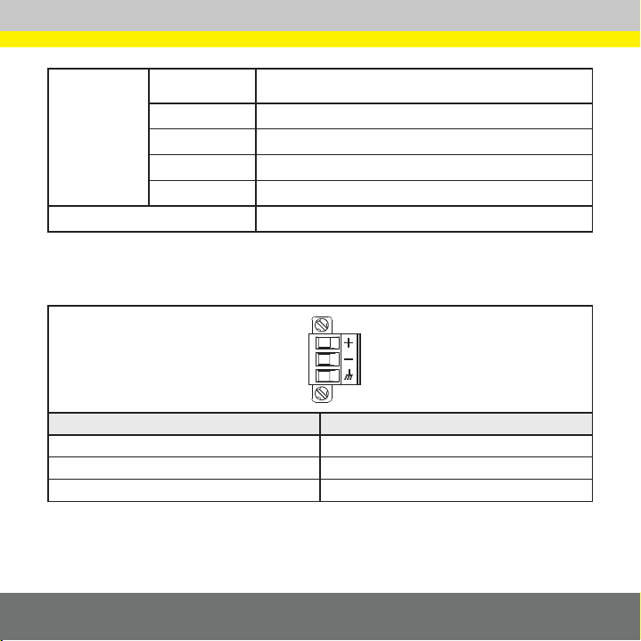
VisionView VGA is intended to be supplied by a NRTL listed power supply with its•
output rated 24VDC, at 1A minimum with a maximum short circuit current rating
of less than 8A and a maximum power rating of less than 100VA and marked
Class 2 or Limited Power Source (LPS). Any other voltage creates a risk of fire
or shock and can damage VisionView VGA components. Applicable national and
local wiring standards and rules must be followed.
To reduce the risk of damage or malfunction due to over-voltage, line noise,•
electrostatic discharge (ESD), power surges, or other irregularities in the power
supply, route all cables and wires away from high-voltage power sources.
Do not install VisionView VGA in areas directly exposed to environmental•
hazards such as excessive heat, dust, moisture, humidity, impact, vibration,
corrosive substances, flammable substances, or static electricity.
VisionView VGA should be mounted with sufficient clearance to allow air•
circulation through the vents.
VisionView VGA does not contain user-serviceable parts. Do not make any•
electrical or mechanical modifications. Unauthorized modifications may void your
warranty.
Changes or modifications not expressly approved by the party responsible for•
regulatory compliance could void the user’s authority to operate the equipment.
VisionView VGA is intended for indoor use only.•
Cable shielding can be degraded or cables can be damaged or wear out more•
quickly if a bend radius or service loop is tighter than 10X the cable diameter.
Service loops should be included with all cable connections.•

3
1
3
5
2
4
6
Legend*
1 = VGA Cable
2 = RJ-45 LAN Cable
3 = Touch Screen
Cable
4 = USB Cable
5 = Power Connector
6 = Ethernet Cables
*The legend numbers also
correspond with the numbered
Installation steps.

4
1Connect the VGA Cable
Connect a VGA cable to VisionView VGA’s VGA port, and connect the other
end of the cable to a monitor or a touch screen’s VGA port.
VisionView VGA Support
VisionView software instructions are presented in detail in the VisionView®Software
Manual, which is included on the VisionView CD and available for download from the
VisionView support site: www.cognex.com/Support/VisionView.
Installation
Note: Cables are sold separately. If any of the contents appear to be missing or
damaged, immediately contact your Cognex Authorized Service Provider (ASP) or
Cognex Technical Support.
2Connect the Network Cable
Connect an RJ-45 cable to VisionView VGA’s LAN port, and connect the other
end of the cable to a switch/router, as applicable.
Notes:
A Cognex vision sensor can be directly connected to VisionView VGA•
LAN port.
The VisionView VGA LAN port does not provide Power over Ethernet•
(PoE) to Cognex sensors.

5
3Connect the Touch Screen Cable
(Optional)
If connecting a touch screen to VisionView VGA, connect the Touch1.
Screen cable’s RJ-12 connector to VisionView VGA’s Touch Screen port.
Connect the other end of the Touch Screen cable to the touch screen’s2.
serial connector.
4Connect the USB Accessories (Optional)
If connecting a USB mouse or keyboard to the VisionView VGA, connect a
USB cable to VisionView VGA’s USB port.
5Connect the Power Cable
Verify the 24VDC power supply being used is unplugged and not1.
receiving power.
Attach the power cable’s -24V wire to Pin 2 and the +24V wire to Pin 32.
on the green power connector supplied with VisionView VGA. Connect a
frame ground wire from Pin 1 to frame ground. Tighten the wire retention
screws.
Insert the green connector into the Power Connector port and tighten the3.
connector screws.
Caution: Do not connect AC power directly to the VisionView VGA
Power Connector.
Restore power to the 24VDC power supply and turn it on if necessary.4.

6
VisionView VGA Specifications
Minimum Firmware Version VisionView 1.3.0
Memory System 128MB Mobile SDRAM
Program 128MB non-volatile flash memory
Video 16MB Video SDRAM
Cooling System Fanless Design
I/O Status LEDs Power
USB 1 Host USB 1.1 (12 Mb/sec.) port for basic HID support (mouse and
keyboard) and for saving images to a USB drive1.
Network 1 Ethernet port, 10/100 BaseT, TCP/IP Protocol, Full Duplex. LEDs
indicate Ethernet network activity.
Touch Screen21 Touch Screen port, RS232 serial protocol
Display 1 VGA port
Power Consumption 24VDC ±10%, input current 1A (maximum). VisionView VGA
contains an internal self-resetting fuse.
Mechanical Material ABS/PC blend (V0 UL Rated) housing
Mounting #3 Din Rail (35mm) or four M4 threaded mounting holes
Dimensions 46.0mm (1.81in) x 138.6mm (5.46in) x 156.0mm (6.14in) (with feet)
Weight 454g (16.0 oz.)

7
Environmental Temperature Operating: 0°C to 45°C (32°F to 113°F)
Storage: -30°C to 80°C (-22°F to 176°F)
Humidity 90%, non-condensing (Operating and Storage)
Protection IP20 or NEMA 1
Shock 30 G Shock per IEC 68-2-27.
Vibration 2 G from 10-2000 Hz. Vibration per IEC 68-2-6.
Regulatory Compliance CE, FCC, TÜV SÜD NRTL, RoHS
Power Connector Specifications
1
2
3
Pin # Signal Name
1 Frame Ground
2 -24VDC (Return)
3 +24VDC (Power)
USB drives should be formatted with a FAT32 file system.1.
Refer to the2. VisionView®Software Manual for details on supported touch screens.

8
Touch Screen Port Specifications
6
1
Pin # Signal Name
1 CTS
2 Not Used
3 TxD
4 GND
5 RxD
6RTS

9
VisionView VGA Dimensions
Note: All dimensions are in mm [inches].
138.6
[5.46]
46.0
[1.81]
105.7
[4.16]
156.0
[6.14]
80.0
[3.15]
26.1
[1.03]
4X M4 X 6mm
23.0
[.91]
11.5 [.45]

10
規制情報/適合宣言
製造者 CognexCorporation
OneVisionDrive
Natick,MA01760USA
マークの付与されたマシンビジョンシステム製品を以下の通り宣言します。
製品タイプ タイプ821-0031-1R
準拠 2004/108/EC電磁両立性指令
適合規格 EN55022:2006+A1:2007(クラスA)
EN55024:1998+A1:2001+A2:2003
EN61000-3-3:1995+A1:2001+A2:2005
EN61000-3-2:2006
EU域内代理人 COGNEXINTERNATIONAL
Immeuble“LePatio”
104AvenueAlbert1er
92563RueilMalmaisonCedex-France
安全規制
FCC FCC(アメリカ連邦通信委員会)規制第15章クラスA準拠
本装置はFCC規則第15章に準拠しており、次の2つの条件を前提として動作します。(1)本装置が有
害な干渉を起こさないこと。(2)本装置が干渉(誤動作を引き起こす恐れのある干渉を含む)を受けて
も耐えること。
本装置は高周波を発生・使用・放射することがあります。取扱説明書の指示にしたがわずに設置・使用し
た場合、無線通信に有害な干渉を与える可能性があります。本装置を住宅地で使用すると有害な電波障
害を起こす恐れがあり、この場合、使用者の負担で障害を是正する必要があります。
NRTL TÜVSÜDAMSCC/NRTLOSHASchemeforUL/CAN60950-1
CB TÜVSÜDAM,IEC/EN60950-1請求により、CB報告を提供します。
RoHS RoHS6準拠
注:規制および適合宣言に関する最新情報については、Cognexオンラインサポートにアクセスしてください。
www.cognex.com/ckksupport/common/welcome.asp

11
注意事項
人体への障害や機器の損傷を防ぐために、VisionViewVGAをインストールする際には次
の注意事項を厳守してください。
VisionViewVGAは、UL規格に準拠した最低定格出力24VDC、短絡定格電流最•
大8A以下、電力定格最大100VA以下の1A、クラス2またはLPS(LimitedPower
Source)による電源供給を必要とします。他の電源を使用すると、火災や感電の危険
性が生じ、ハードウェアに損傷を与える原因となります。必要に応じて、国および地域
の配線規格および規則に従ってください。
過電圧、回線ノイズ、静電気放電(ESD)、電力サージ、そのほかの電源異常に起因し•
た損傷や誤作動を防止するために、ケーブルとワイヤはすべて高電圧電源を避けて
配線してください。
過度の熱、ほこり、水分、湿度、衝撃、振動、腐食性物質、可燃性物質、静電気などの環•
境下に、保護筐体なしでVisionViewVGAを設置しないでください。
換気口を通して空気循環ができるように、周囲に十分なスペースを空けて•
VisionViewVGAを設置してください。
VisionViewVGAには、ユーザが修理できる部品はありません。電気的または機械•
的な改造を加えないでください。許可なく改造を行った場合は、保証が無効になり
ます。
各種規格関連団体からの明示的な了承なしに変更、改造を行った場合は、本機器の•
使用権限を失う可能性があります。
VisionViewVGAは屋内設置用として設計されています。•
曲げ半径またはサービスループがケーブルの直径より10倍より小さい場合、ケーブ•
ルのシールドの劣化、ケーブルの損傷または磨耗が短期間で生じることがあります。
サービスループは、すべてのケーブル接続に含まれている必要があります。•

12
1
3
5
2
4
6
凡例*
1=VGAケーブル
2=RJ-45LANケーブル
3=タッチスクリーン
ケーブル
4=USBケーブル
5=電源コネクタ
6=イーサネットケーブル
*凡例中の番号は、取り付けステ
ップに対応しています。

13
1VGAケーブルの接続
VGAケーブルをVisionViewVGAのVGAポートに接続し、もう一 端 を モ ニタま た
はタッチスクリーンのVGAポートに接続します。
VisionViewVGAのサポート
VisionViewソフトウェアの使用方法については、『VisionView®ソフトウェアマニュア
ル』をご覧ください。このマニュアルは、VisionViewCDに同梱されていますが、以下の
VisionViewサポートサイトからも無償でダウンロードできます。
www.cognex.com/ckksupport/common/welcome.asp
VisionViewVGAの取り付け
注:ケーブルは別途ご購入ください。内容物が無い、もしくは損傷している場合、至急、弊社
代理店(ASP)またはテクニカルサポートまでご連絡ください。
2ネットワークケーブル の 接 続
RJ-45ケーブルをVisionViewVGAのLANポートに接続し、もう一端を必要に応
じてスイッチ/ルータに接続します。
注:
Cognexビジョンセンサは、VisionViewVGALANポートに直接接続するこ•
とが可能です。
VisionViewVGALANポートは、CognexセンサにPoE(パワーオーバイー•
サネット)電源を供給しません。

14
3タッチスクリーンケーブルの接続(オプション)
タッチスクリーンをVisionViewVGAに接続する場合、タッチスクリーンケ1.
ーブルのRJ-12コネクタをVisionViewVGAのTouchScreenポートに接続
します。
タッチスクリーンケーブル のもう一端をタッチスクリーンのシリアルケーブ2.
ルに接続します。
4USBアクセサリの接続(オプション)
USBマウスまたはキーボードをVisionViewVGAに接続する場合、USBケーブル
をVisionViewVGAのUSBポートに接続してください。
5電源ケーブルの接続
24VDC電源装置から電源が出力されていないことを確認してから接続しま1.
す。
VisionViewVGAに付属している緑色の電源コネクタの2番ピンに電源ケー2.
ブルの-24Vワイヤを接続し、3番ピンに+24Vワイヤを接続します。必要に
応じて、1番ピン(シールド)のワイヤをフレームグラウンドを接続してくださ
い。ワイヤの固定ねじを締めます。
緑 色 のコ ネクタを 電 源コ ネクタポ ートに 挿 入し、コネクタねじで締めてくだ3.
さい。
警告:AC電源を直接VisionViewコネクタに接続しないでください。
24VDC電源をONにしてください。4.

15
VisionViewVGA仕様
対 応 ファー ムウェアバ ー ジョン VisionView1.3.0
メモリ システム 128MBモバイルSDRAM
プログラム 128MB不揮発性フラッシュメモリ
ビデオ 16MBビデオSDRAM
冷却装置 ファンレス 設 計
I/O ステータスLED 電源
USB ベーシックHIDサポート(マウスおよびキーボード)およびUSBドライ
ブ1に画像を保存するホストUSB1.1(12MB/秒)ポート×1
ネットワーク イーサネットポート×1、10/100BaseT、TCP/IPProtocol、全二重。LED
はイーサネットのネットワーク活動を表示。
タッチ スクリー ン 2TouchScreenポート×1、RS232シリアルプロトコル
ディスプレ イ VGAポート×1
消費電力 24VDC±10%、1A(最大)。自己復帰型ヒューズ内蔵。
機械的仕様 材質 ABS/PCブレンド(V0UL規格)ハウジング
取り付け #3Dinレール(35mm)またはM4ネジ穴×4
寸法 46.0x138.6x156.0mm(足付き)
重量 454g

16
環境 温度 動作:0〜45°C
保存:-30°〜80°C
湿度 90%、結露しないこと(動作および保管)
保護 IP20またはNEMA1
衝撃 IEC68-2-27準拠、30G
振動 IEC68-2-6準拠、10〜2000Hzの範囲で2G
規格承認 CE、FCC、TÜVSÜDNRTL、RoHS
電源コネクタの仕様
1
2
3
ピン番号 信号名
1 フレームグラウンド
2 -24VDC(リターン)
3 +24VDC(電源)
USBドライブはFAT32ファイルシステムにフォーマットしてください。1.
サポートするタッチスクリーンについての詳細は、『VisionView2. ®ソフトウェアマニュアル』をご参照ください。

17
TouchScreenポートの仕様
6
1
ピン番号 信号名
1 CTS
2 未使用
3 TxD
4 GND
5 RxD
6 RTS

18
VisionViewVGA寸法図
注:寸法はmm単位で表示されています。
138.6 46.0
105.7
156.0
80.0 26.1
4X M4 X 6mm
23.0
11.5
Other manuals for VisionView
2
This manual suits for next models
1
Table of contents
Popular Video Card manuals by other brands

Asus
Asus Vanta 2000 Series user manual

Conrad
Conrad 87 46 82 operating instructions

ATI Technologies
ATI Technologies 100-505531 - Firepro 2450 PCIE16 512MB 4PORT Dvi... Specifications

MSI
MSI RX1600XT-T2D256E Quick user guide

Diamond Multimedia
Diamond Multimedia ATI Radeon HD 4650 PCIE Specification sheet

HP
HP NVIDIA Quadro FX 1700 Quickspecs