Cognisys StopShot User manual

Turningordinarymomentsintoextraordinarypictures
Owner’sManual
Revision1.6
Copyright2009Cognisys,Inc.

TableofContents
1.SAFETYINSTRUCTIONS...............................................................................................................................4
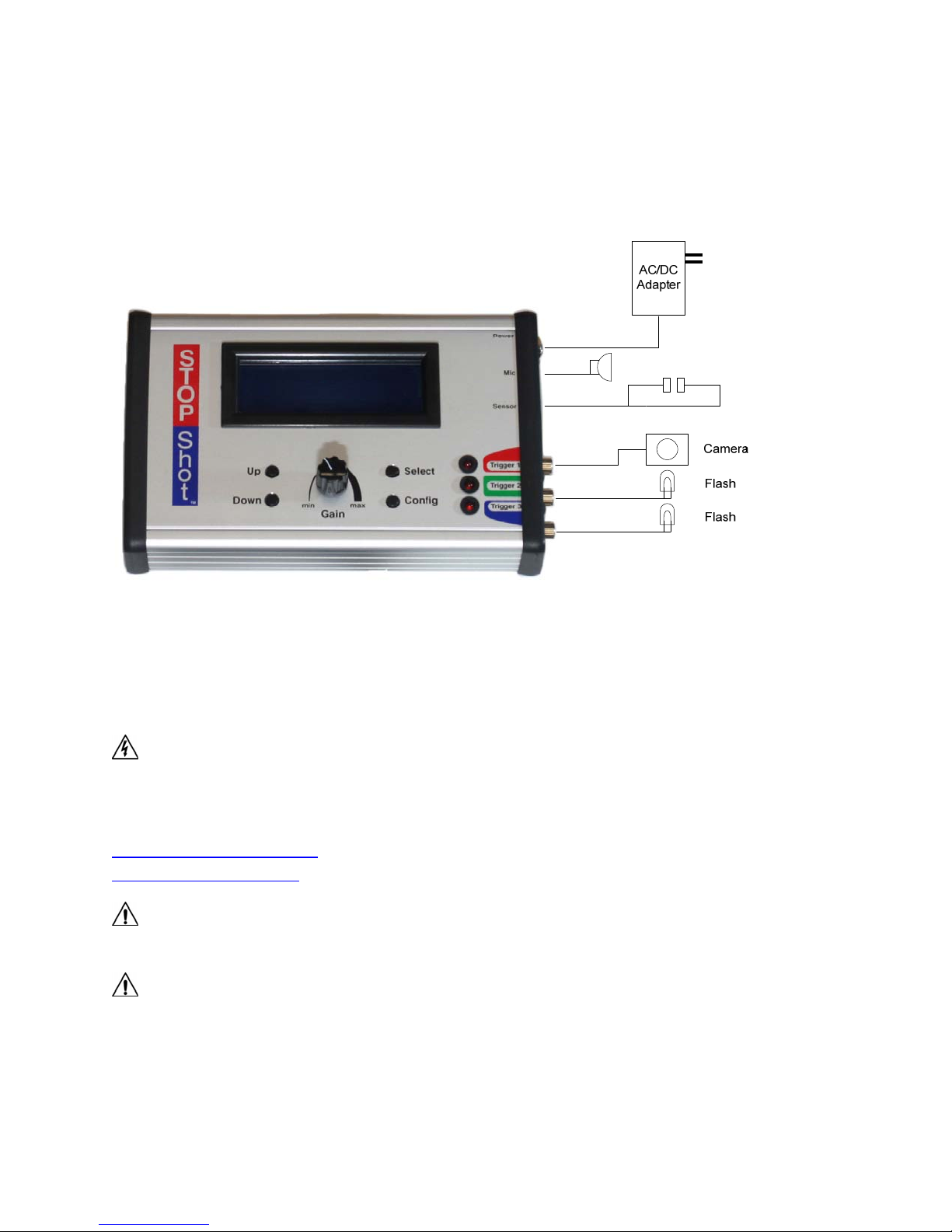
2.GETTINGSTARTED.....................................................................................................................................4
3.OPERATION...............................................................................................................................................7
3.1OVERVIEW.......................................................................................................................................................7
3.2GAINCONTROL.................................................................................................................................................7
3.3GLOBALCONFIGURATION...................................................................................................................................8
3.3.1GlobalTriggerModeOverview................................................................................................................8
3.3.2Loading/Savingconfigurations................................................................................................................8
3.3.3LoadDefaults.........................................................................................................................................10
3.3.4Backlighting...........................................................................................................................................10
3.3.5SensorPowerOff...................................................................................................................................10
3.3.6PowerOffDuration................................................................................................................................11
3.3.7SequentialTimeout................................................................................................................................12
3.4OUTPUTCONFIGURATION.................................................................................................................................13
3.5INDEPENDENTTRIGGERING...............................................................................................................................13
3.5.1Overview................................................................................................................................................13
3.5.2Manual...................................................................................................................................................14
3.5.3Trigger....................................................................................................................................................15
3.5.4Cross‐Beamsensormodes.....................................................................................................................17
3.5.5Ballistics.................................................................................................................................................19
3.6SEQUENTIALTRIGGERING..................................................................................................................................21
3.6.1Overview................................................................................................................................................21
3.6.2ManualTrigger......................................................................................................................................23
3.6.3InputTrigger..........................................................................................................................................23
3.6.4DelayedTrigger......................................................................................................................................23
3.7TIME‐LAPSE...................................................................................................................................................26
3.8FLASHDURATIONMEASUREMENT......................................................................................................................27
4.ACCESSORIES............................................................................................................................................30
5.CONNECTIONS&CABLES..........................................................................................................................40
5.1SENSOR/MICINPUTS.......................................................................................................................................40
5.2TRIGGEROUTPUTS..........................................................................................................................................40
5.3ACTIVATINGRELAYS.........................................................................................................................................41
5.4CROSS‐BEAMSENSOR......................................................................................................................................42
6.TROUBLETRIGGERING..............................................................................................................................44
7.SETUPEXAMPLES(GETTINGTHEULTIMATESHOT)....................................................................................45
7.1WATERDROPS...............................................................................................................................................45
7.1.1Water‐dropHow‐to...............................................................................................................................47
7.2BALLISTICS–TIPSANDTRICKS...........................................................................................................................50

8.ANIMATEDTIME‐LAPSEMOVIES...............................................................................................................51
9.TROUBLESHOOTING..................................................................................................................................52
10.SPECIFICATIONS....................................................................................................................................53
11.WARRANTY..........................................................................................................................................54
12.GLOSSARY............................................................................................................................................55
13.REVISIONHISTORY................................................................................................................................57
TableofFigures
Figure1‐TypicalConnectionDiagram.........................................................................................................5
Figure2‐SensorPowerDisable.................................................................................................................12
Figure3‐ManualModeTimingDiagram...................................................................................................15
Figure4‐TriggerTimingDiagram...............................................................................................................17
Figure5‐BallisticsTiming...........................................................................................................................20
Figure6‐SequentialModeTimingDiagram..............................................................................................22
Figure7‐DelaySynchronization.................................................................................................................25
Figure8‐TimeLapseTimingDiagram........................................................................................................27
Figure9‐FullPowerFlashOutput..............................................................................................................29
Figure10‐SixteenthPowerFlashOutput..................................................................................................29
Figure11‐MicrophoneConnection...........................................................................................................40
Figure12‐SensorConnection....................................................................................................................40
Figure13‐RCAconnector..........................................................................................................................41
Figure14‐Wiringanexternalrelay............................................................................................................42
Figure15‐Cross‐beamconnections...........................................................................................................43
Figure16‐LaserDiffuser............................................................................................................................44
Figure17‐ASuckerbeingShotwitha.22CaliberRifle.............................................................................50

1. SafetyInstructions
WARNINGindicatesapotentiallyhazardoussituationwhich,ifnotavoided,couldresultindeath
orseriousinjury.
FollowallCAUTIONnoticestoreducetheriskofpersonalinjury,preventdamagetothe
StopShotmodule,accessories,anddevices(cameras,flashes,etc).FailuretofollowallCAUTION
noticesmayvoidyourwarranty.CAUTIONmayalsoindicateapotentiallyhazardoussituation
which,ifnotavoided,mayresultinpersonalinjury.
ThesafetyalertsymbolprecedesageneralCAUTIONorWARNINGstatement.
TheelectricalhazardsymbolprecedesanelectricshockhazardCAUTIONorWARNING
statement.
2. GettingStarted
Thelatestversionofthismanualisavailableathttp://www.cognisys‐inc.com.
TheStopShotdeluxepackagecontainsthefollowing:
1. StopShotModule(1)
2. AC/DCPowerAdapter(1)
3. OperationManualCD(1)
4. BeamSensor–InfraredTransmitterandReceiver
5. OakBaseforSensorcomponents
6. 3in‐PCtoFemaleRCACable
7. 6ft‐RCAM/MCable
8. 6ft‐3.5mmM/MCable
9. 6ft‐2.5mmM/MCable
Toconnectthebeamsensorusethe3.5mmcableandconnectoneendtothejacklabeled“Sensor”on
StopShotandtheotherendofthecabletotheIRreceiverasshownbelowinFigure1.Thenusethe
2.5mmcabletoconnectthetransmitterandreceivertogether.The2.5mmcableprovidespowerfrom
thereceivertothetransmitter.

PowertotheStopShotmoduleisprovidedthroughanACtoDCpoweradapter.Plugthepoweradapter
intotheStopShotmodulejacklabeled“Power”,andplugtheadapterintothewall.Theunitwillpower
up,displayasplashscreen,andthencontinuetothemainscreen.
FlashesandshuttercontrolshouldbeconnectedtotheTrigger1,Trigger2,and/orTrigger3RCAjacks.
Figure1‐TypicalConnectionDiagram
WARNING:HighvoltageflashesshouldNOTbeconnectedtotheStopShotmoduleoranyofits
associatedadapters/connectors/cables.Doingsocouldexposeyoutodangerouslyhighvoltages
resultinginseriousinjuryordeath.Allnewflashesonthemarketdonotexposehighvoltageonthe
hot‐shoe.ThesearetheflashesintendedforusewiththeStopShotmodule.Pleasevisitourweb‐siteat
http://www.cognisys‐inc.comforalistoflow‐voltageflashes,orcontactusviae‐mailat:
support@cognisys‐inc.com.
WARNING:DonotuseStopShottoautomatethefiringofballistics.Seriousinjuryand/ordeath
mayoccur.
CAUTION:Onlyusethepoweradapter(cube)thatcamewiththeStopShotmodule.Useofother
poweradaptersmaydamagethemodule.

CAUTION:Donotuse“Y”adaptersforthetriggeroutputstoconnectmorethanthreedevices.
Somedevicesgeneratesignificanttransients(likesolenoids)thatmaydamagesensitiveequipmentsuch
ascamerasandflashes.StopShotisprotectedfromthesetransientsbutotherelectronics(suchas
flashesandcameras)maynotbe.Itisacceptabletousea“Y”adaptertoconnectmorethanonedevice
toatriggeroutputaslongasthedevicesaresimilar.Ifyouhaveanyquestionsorconcernsaboutdevice
compatibility,pleasecontactusat:
support@cognisys‐inc.com.

3. Operation
3.1 Overview
StopShotallowsprecisecontroloverflashes,cameras,andotherelectronicdevices.Itmaybe
configuredtogivevirtuallyanycombinationorsequenceofevents.Thisallowsforseveral
differenteffects:Stoppingwaterdropsintime,projectilespausedatthemomenttheypierce
andobject,oreventime‐lapseimagery.Oncecomfortablewithsimplesettings,advanced
triggeringcanbeusedtocoordinatecomplexseriesofevents:Pushingabuttontoreleasea
waterdropfromasolenoidcontrolledvalve,crossingthroughabeamsensor,andthenfiringa
high‐speedflash.
TheSELECTbuttonmovesthecursorfromlinetolineonthedisplay.TheUPandDOWNbutton
adjustthevaluesforeachline.Thedifferentmodesofoperationarelistedinsubsequent
sections.
Settingswillbesavedacrosspowercycles.
3.2 GainControl
ThegainknobisusedtoadjustthesensitivityofStopShottothetriggerinputs.Ifusingthe
microphoneandthemicrophonegainissettominimum,itwouldtakealoudernoisetocause
StopShottotrigger(becausethesensitivityisturneddown).Ifthegainissettomaximum,then
quietnoiseswilltrigger.IfambientnoiseistriggeringStopShotthenturnthegaindown.
Whenusingthestandardbeamsensorthegainmaybeusedtoadjustthesensitivity.Decrease
thegainifthesensoristriggeringfalselyduetoambientlightornoise.Formostapplications
thatusetheIRandlaserbeamsensorsthegainshouldbesettothemiddleposition.Digital
inputssuchasthecross‐beamsensorsshouldalsohavethegainsettothemiddleposition.
Toavoidfalsetriggersisalwaysbesttokeepthegainatthelowestsettingwhilestillreliably
triggering.IftheLEDforaparticularchannelisonorflashingtryturningthegaindownto
correctthisissue.YoumayseethisifyouhaveasensorcableattachedtoStopShotwithno
sensorpluggedinandthegainturnedallthewayup.

3.3 GlobalConfiguration
ToenterStopShot’sGlobalConfiguration,pressandholdtheCONFIGbuttonfortwoseconds.
Thedisplaywillchangetoindicatethatyouarenowinthe“GlobalConfig”menu.Toreturnto
themainscreenpresstheCONFIGbutton.
3.3.1 GlobalTriggerModeOverview
Therearefouravailableglobaltriggermodes(“TMode”).The“Independent”mode(default)
meansthatifalltheoutputchannelsareconfiguredastriggers,onceaninputeventoccurs
(aninfra‐redbeamiscrossed,orasoundthresholdisexceeded)allthreeoutputswill
functionsimultaneously.Forexample,ifeachoutputtriggerisconfiguredfora5msdelay,
allthreeoutputswilltriggeratthesametime.Theyareindependentbecausetheydonot
dependonthestateofanyothertrigger.Otherpossibletriggeringoptionsarediscussedin
section3.5.
Ifthe“TMode”inGlobalConfigurationissetto“Sequential”andallthreetriggeroutputsare
setto5ms,thefirsttimeaninputeventoccurredthefirstoutputwouldfire,thenextinput
eventwouldcausethesecondoutputtofire,thethirdinputeventwouldcausethefinal
thirdoutputtofire.Eachtriggeroutputmaybeconfiguredtohandletheinputevent
differentlyandtheoptionsarediscussedinsection3.6.Ifallthedifferenttypesof
configurationsarescaringyou–don’tworry.We’llwalkyouthroughthemstepbystep.In
thesection7ofthismanual,we’llshowyouexactlywhatsettingsarebeingused,howthe
shotwasphysicallysetup,andthepictureweendedupwith.
Anotheravailable“TMode”is“TimeLapse”.ThisallowstheTrigger1outputtobefiredata
specifiedinterval.Forhelpwiththismodepleaseseesection3.7.
ThefinalmodeisFlashDuration(“Fduration”).Thismodeallowsyoutomeasurethe
durationofaflash.Seesection3.8formoredetails.
3.3.2 Loading/Savingconfigurations
StopShotautomaticallysavesthelastsettingsused,butsometimesitismoreconvenientto
savedifferentconfigurationsfordifferentsetups(oneconfigurationforinsects,anotherfor
water‐drops,andyetanotherforballistics).Toloadorsavethesettings,presstheSELECT
buttonuntilthecursorisnextto“Load/SaveConfig”andpresstheUPorDOWNbuttonto
enterthenextscreen.
== Global Config ==
TMode: Independent
Load/Save Config
Load Defaults: ->
>

Fromthisscreenyouhavetwooptions–toeitherloadorsavetheconfiguration.Pressthe
SELECTbuttontochangebetweenthetwooptions.Underthe“Load”screen,youwillsee
thefollowing:
== Load Config ==
1. <empty>
Up/down to select.
UsingtheUPorDOWNbuttons,youcanscrollthroughthetenavailableconfigurationsto
retrieve.Iftheyhaveneverbeenloadedwithaconfigurationbeforeitwillshowupas
“empty”otherwiseitwillshowthenameyouhadpreviouslysaved.Onceyouhave
highlightedthedesiredconfigurationtoload,presstheSELECTbutton.Thiswilltakeyouto
themainscreenforthisconfiguration.Youcanaborttheloadingscreenbysimplypressing
theCONFIGbutton.
Theprocessissimilarforsavingaconfiguration.Once“Save”isselected,youwillseethe
followingscreen:
== Save Config ==
1. <empty>
Up/down to select.
UsetheUPorDOWNbuttonstoselectwhichconfigurationyouwouldliketosave.Youcan
overwritepreviouslystoredconfigurations.Oncethedesiredconfigurationisselected,
presstheSELECTbutton.Atthispointyoucanenteraname.Thecursorunderlinesyour
currentposition.TheUPandDOWNbuttonsmaybeusedtochangethecharacters.Each
timeSELECTispresseditwilltakeyoutothenextcharacterposition.Keeppressingselect
untilallthecharactershavebeenentered(Atotalof12maybeused).Notallspacesneed
tobefilled,justkeeppressingselecttofinishtheentry.Uponsavingtheconfigurationthe
screenwillshow:
== Save Config ==
1. Drop on drop
Saved. Cfg exits.
Up/down to select.
Inthiscasethesettingnamewassetto“DroponDrop”.PresstheCONFIGbuttontoexitto
themainscreen.

3.3.3 LoadDefaults
== Global Config ==
TMode: Independent
Load/Save Config
Load Defaults: ->
>
Oncethisoptionisselected,pressingtheUPorDOWNbuttonwillresetallthecurrent
settingsinStopShottothefactorydefault.Ifyou’vechangedtheconfigurationsinto
somethingwhereitjustisn’tdoingwhatyouexpectedoritwilltakelongertogeteverything
backtoaninitialcondition–usethisoption.Bewarethatbyselectingthisoptionallthe
currentsettingswillbelost.Note:Thisactionwillnoteraseyourpresets.
3.3.4 Backlighting
== Global Config ==
> LCD Backlight: 10
Pwr Off: None
Pwr Toff: off ->
Backlighting(“LCDBacklight”)isonthesecondconfigurationpageandistheamountoflight
thatthedisplaygeneratessothatyoucanseethetextonthescreen.Itmaybebeneficialto
adjustthebacklightinglowerifworkinginlowlightsituations.Thispreservesyoureyes
sensitivitytolightandalsodoesn’tcauseunwantedsecondarylightinyourexposure.To
increasethebacklighting,presstheUPbutton.Todecreasethebacklighting,pressthe
DOWNbutton.Thebacklightingmaybeadjustedfromarangeof1–10.
3.3.5 SensorPowerOff
== Global Config ==
LCD Backlight: 10
Pwr Off: None
Pwr Toff: off ->
>
StopShothastheabilitytodisablesensorpoweronceaninputeventoccurs.Thisfeatureis
extremelyusefultodisablelasertransmitterspriortotriggeringacameraorflash.The
availableoptionsforthisPowerOff(“PwrOff:”)modeare:
1. “None”:Thefeatureisdisabledandthesensor(s)willremainpowered.
2. “Trig1”:SensorpowerwillbedisabledwhenaninputsatisfiesTrigger1.
3. “Trig2”:Sameas#2above,butwithTrigger2.
4. “Trig3”:Sameas#2above,butwithTrigger3.
5. “All”:Ifanyofthethreetriggerconditionsaresatisfiedthesensorpowerwillbe
disabled.

Thesensorpowerisimmediatelydisabledwhenaninputconditionissatisfied.Ifatrigger
outputisconfiguredfora50msdelay,thepowerwillbedisabledimmediatelywhenan
inputeventoccurs,wait50ms,andthenactivatethetriggeroutput.Thedifferenttrigger
outputmodesforStopShotarediscussedinsection3.4.
Note:Animportantconsiderationwhenusingthismodeisthatitmaypreventother
triggersfromseeinganinputforthedurationthatthesensorpowerisdisabled.
3.3.6 PowerOffDuration
== Global Config ==
LCD Backlight: 10
Pwr Off: None
Pwr Toff: off ->
>
Thissetting(“PwrToff”)allowstheadjustmentofthedurationthatthe“SensorPowerOff”
featurediscussedinsection3.3.6willleavethesensor(s)disabled.Thisdurationisonly
usedifthe“PwrOff”settingissettoavalueotherthan“None”.UsetheUPandDOWN
buttonstoadjusttheduration.Thesensorcanbedisabledlongerthanthedelaythata
triggeroutputisconfigured.Anysensoractivitywillbemissedforthedurationofthis
powerofftimesincethesensor(s)aredisabled.
SeeFigure2belowtodemonstratethebehaviorofthisfeature.

Figure2‐SensorPowerDisable
ThistimingdiagramshowsTrigger1configuredfora100msdelay,“PwrOff”setto“Trig1”,
and“PwrToff”setto300ms.Thesensorisimmediatelydisabledwhentheinputevent(for
examplealaserbeambeingcrossed)occurs.There‐enablingofthesensorpoweroccurs
independentlyfromtheTrigger1delayconfiguration.Don’tworryaboutallthesesettings
yet–they’rediscussedindetailstartingwithsection3.4.
3.3.7 SequentialTimeout
== Global Config ==
> SEQ Tout: off ->
Sequentialtimeout(“SEQTout”)isonlydisplayedifyourtriggermode(Seesection3.3.1)is
setto“Sequential”.Oncethetriggermodeissetappropriatelyanarrowinthebottomright
handcornerofthedisplayappearsindicatingthatadditionalsettingsareavailable.
ContinuepressingtheSELECTbuttonpast“LoadDefaults:”toreachthesecondpage.
Sequentialtimeoutisusefultoabortasequenceifallofthetriggeringconditionsarenot
metwithinthespecifiedamountoftime.Whenasequenceisaborteditwillreturntothe
firstenabledtriggerinthesequence.TheUPorDOWNbuttonsadjustthevalueofthis

timeout.ToreturntothepreviousconfigurationscreenpresstheSELECTbuttonagain.To
disablethesequentialtimeout(whichwillcausethesequencetowaitforever)isachieved
byholdingtheDOWNbuttonuntilthetimeoutreacheszero.“Off”willbedisplayedwhenit
isdisabled.Seesection3.6formoredetailsregardingSequentialoperation.
NOTE:Sequentialtimeoutmaycausesome“curious”behaviorwhichmayappearas
StopShotnotworkingproperly.Thisisbecausethetimeoutwillabortthesequenceand
restartit(whichisitsintendedfunction).Ittakesprecedenceoveranyactivetrigger.Make
sureyou’recomfortablewithyoursettingspriortoenablingthetimeout.Asalways,contact
uswithanyquestions.
3.4 OutputConfiguration
Fromthemainscreen,theSELECTbuttonmovesfromonetriggeroutput(“Trigger”)tothenext.
Tochangetheoutputdelay(ifsoconfigured)youmaypressandreleasetheUPorDOWN
button,orholdthebuttondowntoautomaticallyincrement/decrementthevalue.Inthisway
oneormoretriggeroutputsmaybeactivated.
Tochangetheconfigurationofeachoutput,firstpresstheSELECTbuttonuntilthecursorisnext
tothe“trigger”outputyouwanttochange.PresstheCONFIGbutton.Thiswillbringupthe
outputconfigurationscreen.Thisscreenenableseachtriggeroutputtobeconfiguredina
differentwaybychangingtheparametersdescribedinthesectionsbelow.Thetriggeroutput
type(“TMode”)isadjustedbyusingtheUPandDOWNbuttons.TheSELECTbuttonmoves
fromoneconfigurationparametertothenext.Ifanarrowappearsontherightsideofthe
screenthatindicatesthatanadditionalscreenofconfigurationsisavailable.Asyoupress
SELECTitwillswitchtothenextscreenautomatically.Toreturnbacktothemainscreen,press
theCONFIGbuttonagain.Themainscreenischangedtoindicatehoweachoutputis
configured.
3.5 IndependentTriggering
3.5.1 Overview
Independenttriggeringmeansthattheoutputtimers/triggersoperatecompletelyindependent
ofeachother.Independenttriggeringisa“GlobalConfiguration”.Oncethisglobal
configurationisset(describedinthe“GlobalConfiguration”section3.3above),theoutput
modesbelowareavailable.

3.5.2 Manual
“Manual”triggermoderequiresanUP/DOWNbuttonpresstoactivate.Tochangeanoutputto
“Manual“configuration,fromthemainscreenpresstheSELECTbuttonuntilthedesiredtrigger
outputisselected.PresstheCONFIGbutton.Thiswillbringupthetimerconfigurationscreen.
PresstheUP/DOWNbuttonsuntilthe“TMode”ischangedto“Manual”.
> T1 Mode: Manual
Pulse: 500.0 ms
Toff: 500.0 ms
# Pulse: 1
Withthistypeofoutputyouhavetheoptionofadjustingthedurationoftheoutputpulsethatis
generated.Itfunctionsexactlyasdiscussedinthe“Trigger”mode(section3.5.3).Thenumber
ofpulses(“#Pulse”)maybesettoavaluegreaterthanoneifmultipletriggeroutputpulsesare
required.Thiscouldbeusedtogeneratemultipleinitialevents(suchasmultiplewaterdrops).
“Toff”isusedastheoff‐timebetweenpulsesprovidedthenumberofpulsesisgreaterthanone.
Thisallowscompleteflexibilityfortheonandoffdurationoftheoutput.
PresstheCONFIGbuttontoreturnbacktothemainscreen.The“Manual”modeisactivatedby
pressingtheUP/DOWNbuttonwhenthecursorisnexttothistriggeroutput.Ifthecursorisnot
nexttothedesiredtriggeroutput,presstheSELECTbuttonuntilthecursorisnexttoit.
Manualtriggeringcanalsobeusedinsequentialmodeforstagingshots.Thisallowsasequence
ofeventstostartuponabuttonpress.Themaximumnumberofpulsesthatcanbegeneratedis
1000.
Onceamanualeventistriggered,itmaybeabortedbypressingeithertheUPorDOWNbutton.
Figure3illustratestheconfigurationbelow:
> T1 Mode: Manual
Pulse: 500.0 ms
Toff: 500.0 ms
# Pulse: 3

Figure3‐ManualModeTimingDiagram
3.5.3 Trigger
Allthreetriggeroutputsmaybeconfiguredtoreacttoasensorinput.Whenatriggeroutput’s
mode(“TMode”)isconfiguredas“Trigger”,aninputeventisrequired.Thisisthemodethatis
requiredforusingabeamsensorormicrophoneinput.Tochangeanoutputto“Trigger”,from
themainscreenpresstheSELECTbuttonuntilthedesiredoutputisselected.PresstheCONFIG
button.ThiswillbringuptheTimerConfigurationscreen.PresstheUP/DOWNbuttonsuntil
the“TMode”ischangedto“Trigger”.
> T1 Mode: Trigger
Pulse: 500.0 ms
Blank: Off
Incrm: Off ->
Inthistriggermodeyouhaveadditionaloptionstomodify(ifrequired).
Pulse:
Withthistypeofoutputyouhavetheoptionofadjustingtheoutputpulsethatisgenerated.
Thisisthe“Pulse”field.Thedefaultis500ms,butmaybeadjustedasnecessaryforyour
application.Someloadsmayhaveaminimumpulsetimebeforetheywilltrigger.Forelectro‐
mechanicaldevicessuchasarelaycontrollingasolenoid,youmayneedtoincreasethistime.
Camerasandflashesaregenerallyedgesensitiveandthepulsedurationcanbeleftatthe
default.Thisdurationmaybeadjustedto“Latch”forsequentialmode,discussedinsection3.6.

Blank:
Additionally,youcanadjust“Blank”,whichistheamountoftimethattheinputisignoredafter
theoutputpulseiscomplete.Let’ssaythefollowingsettingsareused:
T1 Mode: Trigger
Pulse: 500.0 ms
> Blank: 200.0 ms
Incrm: Off ->
Inthisexample,“Pulse”issetto500ms,and“Blank”issetto200ms.Whenaninputevent
occurs(forexample,abeamsensorbeingcrossed),thetriggeroutputwilldelaybywhatever
valueisenteredonthemainscreen,generatea500mspulse,andthenwait200msbefore
lookingforaninputagain.“Blank”isusefulforignoringallbutthefirstofaseriesofrapidly
occurringevents.Ifthetriggeroutputisbeingusedtocontrolaflashthisallowstimeforitto
fullychargebeforetriggeringagain.
Incrm:
Thistimermodehastheoptiontoautomaticallyincrementthetimer’smaindelayeverytimean
eventoccursbyadjustingthe“Incrm”configuration.Ifaneventiseasilyrepeatableandthis
incrementissetyoucancreateasimulated“timelapse”forsomequicklyoccurringevent(likea
dropofwaterfalling).
Ifthisvalueissetto10.0ms,andfromthemainscreenthetriggeroutputissetto100.0ms,
everytimeatriggeroccursthedelaywouldincreaseby10ms.Thedelaysettingwillbeupdated
onthemainscreenfollowingeachtriggerevent.Thefirsttimethetriggerwouldwait100ms.
Thesecond:110ms.Thethird:120ms.EverytimeStopShotactivatesthetriggeroutputthe
delayonthemainscreenwillbeincrementedbythe“Incrm”value.Ifyouwanttostartthe
sequenceoversimplyadjustthetriggeroutputvalueonthemainscreenbacktoitsoriginal
valueusingtheUP/DOWNbuttons.
Toff:
“Toff”appearsafteryoupressSELECTonthe“Incrm”setting.Thesecondpageofconfigurations
forthistriggeroutputwillappear.
> Toff: 100.0 ms
# Pulse: 1
->
Seethesection3.5.2“Manual”Triggeringforadditionalinformationregarding“Toff”.

#Pulse:
“#Pulse”specifiesthenumberofpulsesthisoutputshouldgenerateoncetriggered.
Seethesection3.5.2“Manual”Triggeringforadditionalinformationregarding“#Pulse”.
Toff: 100.0 ms
> # Pulse: 1
->
Figure4demonstratesthetimingfunctionalityofthe“Trigger”mode.Thetimingeventsare
initiatedontherisingedgeofthesensorinput(“TriggerIn”below).
Trigger In
Trigger Out
Pulse Blank
Delay Pulse
Delay
+ incrm
Beam sensor crossed
Output triggers Sensor ignored during
blanking timeBeam sensor crossed
Output triggers
Figure4‐TriggerTimingDiagram
3.5.4 CrossBeamsensormodes
Ifyouhavepurchasedthecross‐beamsensoradditionaltriggermodesareavailable.These
modesarepresentinallStopShotmodulessoifyoudecidetopurchasethebeamsensorata
laterdatenosoftwareupgradeisrequired.Thecrossbeamsensoropensupamultitudeof
optionsforcreativetriggeringespeciallyforcapturingthingsinthenaturalworldlikeinsectsand
birds.
Tochangeatriggeroutputtooneofthecross‐beamsensorconfigurations,fromthemain
screenpresstheSELECTbuttonuntilthedesiredtriggeroutputisselected.PresstheCONFIG
button.ThiswillbringuptheTimerConfigurationscreen.PresstheUP/DOWNbuttonsuntil
the“TMode”ischangedtothedesiredcross‐beammode.Thesearediscussedbelow.
Seesection“5.4‐Cross‐beamSensor”forinstructionsonconnectingthissensor.

3.5.4.1 XBeamA
Inthistriggermodeconfigurationonlycrossingbeam“A”ofthecross‐beamsensoris
consideredatriggercondition.Crossingbeam“B”orbothsimultaneouslywillhaveno
effect.Forthismodetoworkproperly,beam“B”mustbeactive(transmitter“B”aligned
withreceiver“B”).Anexampleofthismodewouldbeusingitinconjunctionwiththe“X‐
BeamB”modetoopenthecamerashutterwhenbeam“A”iscrossedandthenfiringthe
flashwhenbeam“B”iscrossed.
3.5.4.2 XBeamB
Thismodefunctionsidenticallyto“X‐BeamA”above,butusesbeam“B”.
3.5.4.3 XBeama&b
Thisisatruecross‐beamconfiguration.Bothbeams“A”and“B”mustbebroken
simultaneouslyforatriggerconditiontobeconsideredvalid.Themainscreenwilldisplay
“XBSa&b”forthismode.Breakingonlybeam“A”or“B”willnotbeconsideredainput
trigger.Thismodeisusefulfordetectingobjectsinatightlycontrolledarea(especiallyif
lasersareused).
Thefollowingconfigurationsareavailableforthissensor:
> T1 Mode: X-Beam a&b
Pulse: 500.0 ms
Blank: 200.0 ms
Incrm: Off ->
Theseconfigurationsfunctionidenticallytothe“Trigger”modeinsection3.5.3.
3.5.4.4 XBeama|b
Inthisconfiguration“A”or“B”willcreateatriggerconditionforStopShot.Themainscreen
willdisplay“XBSa|b”.Usethissensormodewhenitdoesn’tmatterwhichsensoris
activated.Thepossibleconfigurationsforthismodeareidenticaltothe“X‐Beama&b”
mode.
3.5.4.5 XBeama>b
Themainscreenwilldisplay“XBSa‐>b”forthismode.Usethismodeifyouwanttotrigger
onanobjectonlymovinginonedirection.Agoodexamplewouldbecapturingabird
enteringanestbutnotleaving.Theconfigurationforthismodeisshownbelow:
> T1 Mode: X-Beam a->b
Pulse: 500.0 ms
Blank: 200.0 ms
Timeout: 250.0 ms ->

“Pulse”and“Blank”functionthesameasthepreviousmodes(seesection3.5.3).“Timeout”
isdiscussedbelow.Whenbeam“A”isbroken,theletter“a”in“XBSa‐>b”onthemain
screenwillbecapitalized(“XBSA‐>b”)toindicatethatthe“A”conditionhasbeenmetand
StopShotiswaitingforthe“B”condition.Ifthe“B”beamisnotbrokenpriortothe
configured“timeout”thentheletter“A”willrevertbacktolower‐caseindicatingthat
StopShotisonceagainwaitingforthe“A”condition.This“timeout”optionisawayforthe
triggertore‐armifevent“B”neveroccurs.Intheexampleofthebirdenteringanest–If
thebirdflewclosetothenestbutdidnotland,itwouldallowStopShottore‐armthetrigger
outputforthenexttimethebirdwouldapproachthenest.
3.5.4.6 XBeamb>a
Thismodefunctionsthesameas“X‐Beama‐>b”butbeam“B”mustbebrokenfirst,
followedby“A”.Thisallowsdirectionreversalthroughthesensorswithouthavingto
physicallymovethem.
3.5.5 Ballistics
Ballisticsmode(“Ballist”onthemainscreen)simplifiestriggeringonobjectsthatpassbetween
twobeamsensors.Forthismodeyoumayusethecross‐beamkitortwoinfra‐redbeams
connectedusinga3.5mm“Y”connector.Thisconfigurationvirtuallyeliminatesthevariability
involvedwithcapturingsomethingthathasanunpredictable(orunknown)speed.Inthismode,
StopShotmeasuresthetimeelapsedbetweenthetwobeamsensorsandthentriggersthe
outputthatduration(plusaconfigurabledelay).BypressingtheCONFIGbutton,youhavethe
followingconfigurationsthatyoumayadjustforthismode:
> T1 Mode: Ballistics
Pulse: 500.0 ms
Timeout: 250.0 ms
Dist mult: 1 ->
Similartotheothermodes,the“Pulse”timeisthedurationthattheoutputwillbeactive.
“Timeout”isthemaximumtimethatanobjectcantaketotravelfromthefirstsensortothe
secondbeforeStopShotresetsitsballisticscapture.Thistimeoutfeatureisusefultoabortthe
captureeventandresetintheeventthatanobjectnevercrossesthesecondsensor.“Dist
Mult”isthedistancemultiplierused.Hereisanexampleofaballisticssensorsetupusingthe
aboveconfiguration.Thefirstandsecondsensorsarespacedexactlysixinchesapartfromeach
other.Ifanobjectcrossesthefirstsensorandthesecondsensorwithin250ms,theoutputwill
firewhentheobjectissixinchespastthesecondsensor.Ifthe“DistMult”wasto“2”,the
outputwillfire12inchesafterthesecondsensor.
SomenotesregardingBallisticsmode:
1. OnlyoneTriggermaybeconfiguredforballisticsmodeatatime.Thisisduetothe
precisecontrolandresourcesrequiredtocreaterepeatabletiming.

2. Thetimetocrossbetweenbeamsensorsmayrangefrom100ustohours.
3. Theobjectmustbetravelingfastenoughtopreventthesensorfromreachinga“steady
state”darkcondition.OtherwiseStopShotwillmeasurethetimebetweenlight‐>dark
thendark‐>light.
4. Despitethename“Ballistics”thismodemayalsobeusedtocapturewildlife.
5. Lasersensorsaremoredifficulttoalignwiththeprojectile.Thebeam‐widthofthelaser
alsorequiresprecisealignment.Werecommendusinginfraredtransmittersfor
capturingsmallprojectiles;theyaremuchmoreforgivingtoalign.
Shownbelowisthetiming,measurement,andoutputtriggeringofBallisticsmode.
Figure5‐BallisticsTiming
Table of contents
Popular Video Card manuals by other brands

Renkforce
Renkforce RF-VDA-310 operating instructions

MSI
MSI NX8600GT-TD1GEZ/D2 Quick user guide

Gainward
Gainward GTX 580 3072MB PHANTOM brochure

KATO VISION
KATO VISION HDCA02 manual

Abit
Abit Siluro GF3 Vio user manual

ATI Technologies
ATI Technologies 9800XT - 100-505076 FireGL 256MB DDR SDRAM AGP 8x Graphics... user guide

Asus
Asus GeForce RTX 2060 Dual EVO 6GB installation guide

Jaton
Jaton 3DForce4Ti4200-8X user manual

ATI Technologies
ATI Technologies X1900 - Radeon XTX 512 MB PCIE Video Card Installation and setup user's guide

Gigabyte
Gigabyte GV-R597D5-2GD-B user manual

Jaton
Jaton 3DForceG-16 user manual

Digital Equipment
Digital Equipment PBXGB-AA owner's guide