7
6X-1047b
7140
INSTALLATION AND OPERATION
transformer in the model 71x5.When this transformer
is installed at pins A and M on the rear panel Bendix
connector must be jumpered together.This can be
done either within the cable plug mating with the
Bendix connector or at the other end of the cable
in the control box assembly, junction box, or other
device that may be used.
Figure 10 shows a cable wiring diagram where
all connector pins associated with power inputs are
carried through the cable to a control panel, junction
box, or similar housing or device.This cable can be
wired at that end for use with either the 24 V ac/dc or
115 V ac versions of the housing.
WARNING
If 24 V ac is applied to a Cable wired for 115 V
ac operation (having the jumper across pins A
and M) 115 V ac will be back-fed out of pins W
and V. This jumper must be removed if a 115 V
ac Camera is to be operated from 24 V ac.
Note that while a 115 V ac housing can be oper-
ated from 24 V ac/dc this results in a condition where
115 V ac is back fed out of the housing onto pins W
and V. To prevent this, the jumper across pins A and M
must first be removed so that this condition does not
exist.
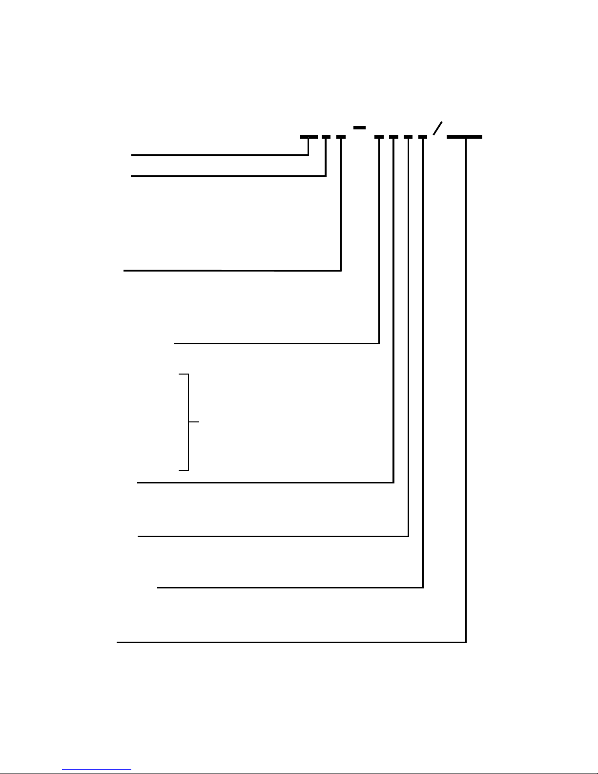
Figure 11 shows a cable wiring diagram for a 115
V ac version of the cable in which pins A and M are
jumpered together within the cable plug attached to
the rear panel Bendix connector..This wiring arrange-
ment should be used when the housing is optioned
with the 115 Vac transformer.This cable cannot be
used to power the housing from 24 V ac/dc because
one required 24 volt wire is not carried through the
cable.
Refer to figure 12 for a
schematic diagram of the hous-
ing.This diagram shows the
internal power wiring of the
housing and also the inter-
connections with the camera
module.
In sum, then:
1. 115 V ac line (high/hot) applied
to pin W and the neutral applied
to pin V. Pin X is the ac power
ground. When this version of the
camera is to be operated from 115
V ac power, pins A and M must be
externally jumpered together.
2. 24 V ac or 24 V dc applied to pins A and d.When 24
volts is to power the camera ensure that pins A and M
are not jumpered together — especially when the op-
tional 115 V ac power transformer has been installed in
the housing.
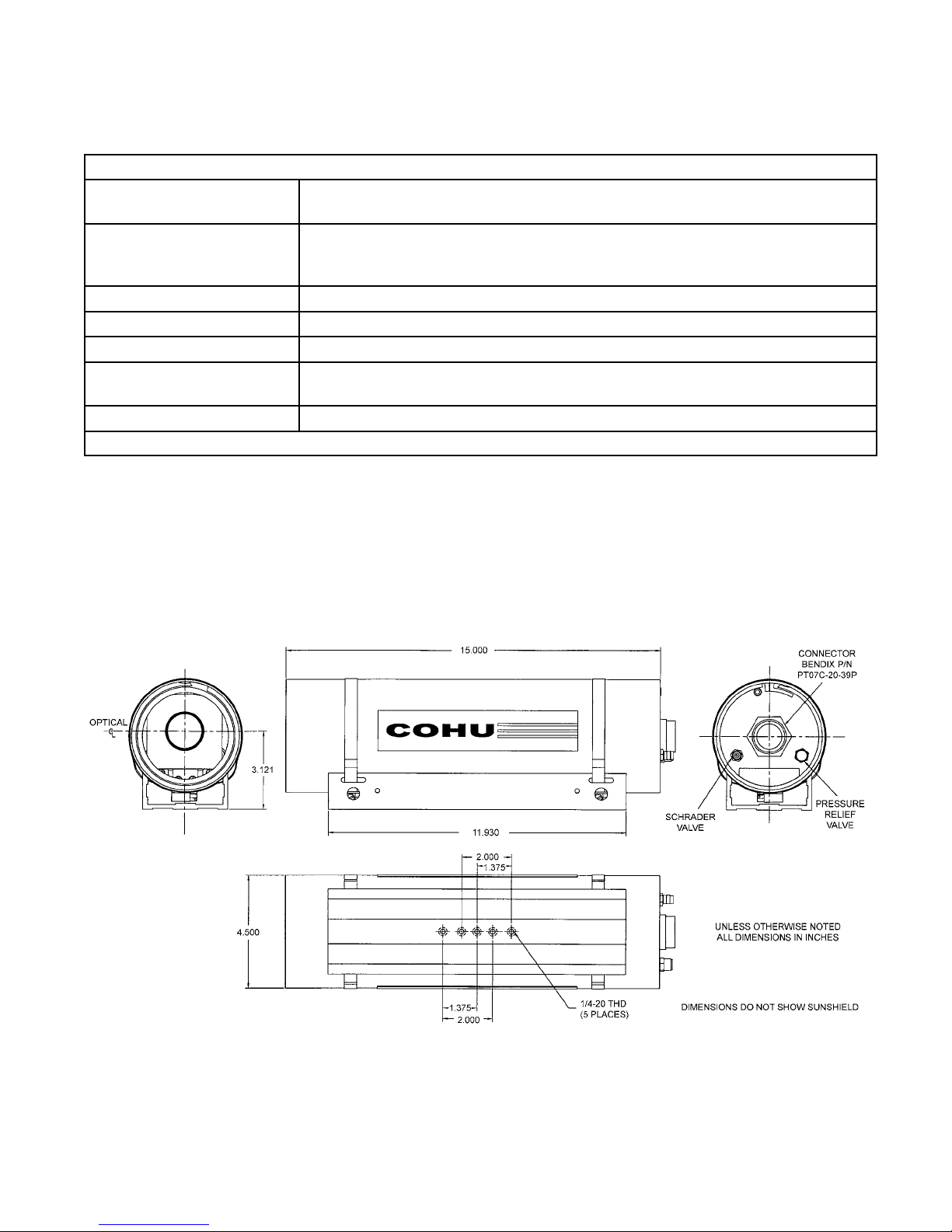
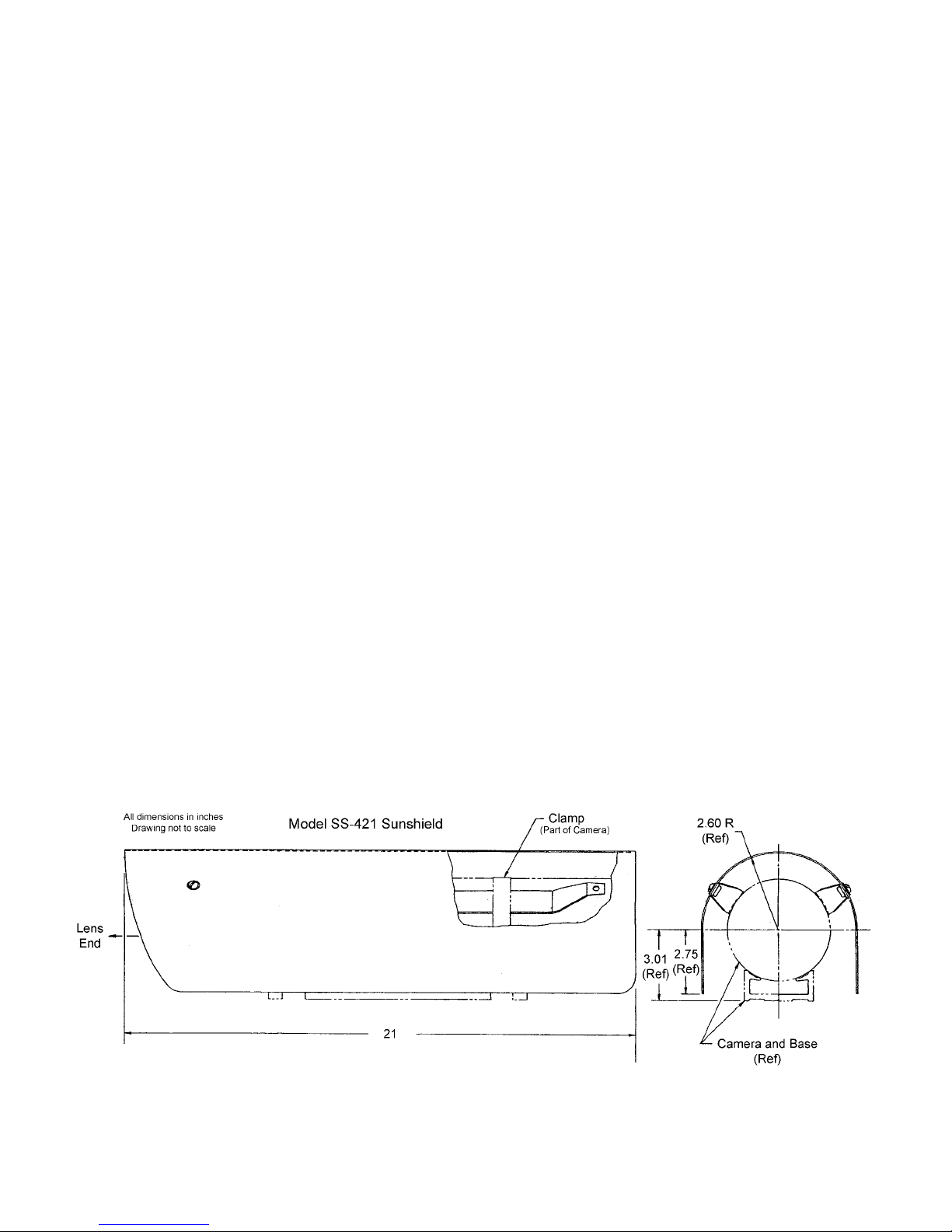
2.5 Mounting Requirements
Five 1/4-20 threaded holes are available on the
base for mounting a Camera. See figure 2. At least two
of these holes should be used. If the camera is to be
mounted outdoors it is likely the sun shield (figure 3)
will be required.This must be attached to the cam-
era before it is mounted to a pole, wall, or other type
device.
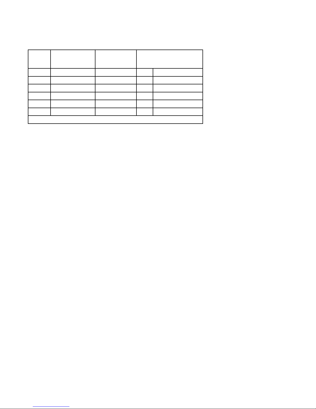
2.6 Camera Module Characteristics
Any one of seven different versions of an inter-
nal camera modules may be installed in the housing
(table 3).These modules have different operating
characteristics as listed in the table.
2.7 Low Pressure Indicator (Option)
The housing is initially pressurized to about
5 psig (pounds square inch gage) (34.5 kPa) of dry
nitrogen. It is possible that this pressure may dissipate
over time, but so long as even a minimal amount of
the dry nitrogen pressure remains in the housing the
camera can be considered operational.When pres-
sure drops to about 1 psig, though, it may be best to
reapply dry nitrogen to bring pressure up to about 5
psig again.
To provide an indication of low pressure, the
housing can be optioned with a low pressure sensor
that provides two indications when pressure drops
Table 3. Camera Module Characteristics
Imager
Model
Resolution
Max Image Size
H & V
Frame Rate at
704 x 480 V
Resolution
Frame Rate
at Max Resolution
(H & V)
301 1280 x 1024 6 ips 1.5 1280 x 1024
302 1600 x 1200 6 1.0 1600 x 1200
303 2048 x 1536 6 0.5 2048 x 1536
601 1280 x 1024 100 + ips 30 1280 x 1024
602 1600 x 1200 100 + ips 20 1600 x 1200
603 2048 x 1536 100 + ips 12 2048 x 1536