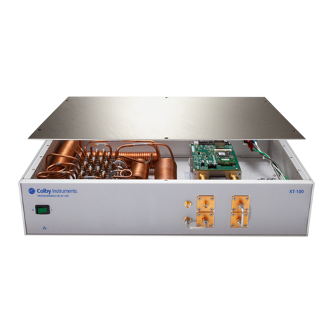
Colby Instruments PDL-100A Owner's manual

-~
ARTISAN
®
~I
TECHNOLOGY
GROUP
Your definitive source
for
quality
pre-owned
equipment.
Artisan Technology
Group
Full-service,
independent
repair
center
with
experienced
engineers
and
technicians
on staff.
We
buy
your
excess,
underutilized,
and
idle
equipment
along
with
credit
for
buybacks
and
trade-ins
.
Custom
engineering
so
your
equipment
works
exactly as
you
specify.
•
Critical
and
expedited
services
•
Leasing
/
Rentals/
Demos
• In
stock/
Ready-to-ship
•
!TAR-certified
secure
asset
solutions
Expert
team
ITrust
guarantee
I
100%
satisfaction
All
tr
ademarks,
br
a
nd
names, a
nd
br
a
nd
s a
pp
earing here
in
are
th
e property of
th
e
ir
r
es
pecti
ve
ow
ner
s.
Find the Colby Instruments PDL-100A-1.25NS at our website: Click HERE

___________________________________
PDL-100A Programmable Delay Line
Operating and Programming Manual
1715 114th Avenue SE
Woodridge Building –Suite 112
Bellevue, WA 98004
(425) 452-8889 VOICE || (425) 452-8802 FAX
www.colbyinstruments.com
Artisan Technology Group - Quality Instrumentation ... Guaranteed | (888) 88-SOURCE | www.artisantg.com
© 2010 Colby Instruments. PDL-100A Operating and Programming Manual.
Hardware Version 1.0 REV 1.0. Firmware Version 1.70.
Artisan Technology Group - Quality Instrumentation ... Guaranteed | (888) 88-SOURCE | www.artisantg.com
© 2010 Colby Instruments. PDL-100A Operating and Programming Manual.
Hardware Version 1.0 REV 1.0. Firmware Version 1.70.
Certification and Warranty
CERTIFICATION
Colby Instruments certifies that the PDL-100A Series of Programmable Delay Line
Instruments meets all published specifications at the time the instruments are shipped
from the manufacturer. SPECIFICATIONS ARE SUBJECT TO CHANGE
WITHOUT NOTIFICATION.
WARRANTY
The product is warranted against defects in material and workmanship for a period of one
year from date of shipment. During the warranty period, Colby Instruments will at its
option, either repair or replace the product or item which proves to be defective.
Replacement products may be either new or like-new.
EXCESSIVE WEAR OF CONNECTORS, THE TROMBONE UNIT, THE
COAXIAL RELAYS, AND OTHER RELAYS CARRYING THE SIGNAL, ARE
NOT COVERED BY THE WARRANTY. THE FOREGOING WARRANTY
SHALL NOT APPLY TO DEFECTS RESULTING FROM IMPROPER CARE
OR USE OF THE INSTRUMENT BY THE BUYER. THIS SHALL APPLY TO
ALL COMPONENTS DELIVERED TO THE BUYER.
For warranty service or repair, this product must be returned to Colby Instruments. The
Buyer shall prepay all shipping charges for the shipment of item to Colby Instruments.
Colby Instruments shall pay the shipping charges to return the product to the Buyer.
However, the Buyer shall be responsible for ALL shipping charges, duties and taxes for
product returned to Colby Instruments from outside the United States of America.
BUYER MUST OBTAIN A RETURN MATERIAL AUTHORIZATION NUMBER
(RMA #) FROM COLBY INSTRUMENTS PRIOR TO THE SHIPMENT OF ANY
ITEM TO COLBY INSTRUMENTS. SHIP TO:
Colby Instruments
Attn: RMA # ________
1715 114th Avenue SE
Woodridge Building –Suite 112
Bellevue, Washington 98004
USA
No other warranty is expressed or implied. Colby Instruments specifically disclaims the
implied warranties or merchantability and fitness for a particular purpose. The remedies
provided herein are the Buyer's sole and exclusive remedies. Colby Instruments shall not
be liable for any direct or special, incidental or consequential damages, whether based on
contract, tort, or any other legal theory.
Artisan Technology Group - Quality Instrumentation ... Guaranteed | (888) 88-SOURCE | www.artisantg.com
© 2010 Colby Instruments. PDL-100A Operating and Programming Manual.
Hardware Version 1.0 REV 1.0. Firmware Version 1.70.
Artisan Technology Group - Quality Instrumentation ... Guaranteed | (888) 88-SOURCE | www.artisantg.com

© 2010 Colby Instruments.PDL-100A Operating and Programming Manual Page i
Table of Contents
Chapter 1.0
Description of the PDL-100A Programmable Delay Line Series ....... 1
1.0.1 Introduction...............................................................................................1
1.0.2 Delay Line Structure and Design ..............................................................2
Chapter 2.0
Getting Started .............................................................................. 3
2.0.1 Using the PDL-100A for the First Time .....................................................3
2.0.2 Self-Test After Power Up..........................................................................4
2.0.3 Self-Test without MT-100A Microterminal connected ...............................4
2.0.4 Self-Test with MT-100A Microterminal connected ....................................5
Chapter 3.0
Using the Front Panel Connections ................................................ 7
3.0.1 Overview of the Front Panel Connections ................................................7
3.0.2 About Series Connected or Parallel Connected Mode .............................8
3.0.3 About Delay Extensions ...........................................................................8
Chapter 4.0
Setting Delay Values......................................................................11
4.1.0 Working with the MT-100A Microterminal...............................................11
4.1.1 The MT-100A Microterminal at a glance.................................................12
4.1.2 Working with the MT-100A Microterminal Keypad..................................13
4.2.0 Setting Delay with the MT-100A Microterminal.......................................15
4.3.0 The MT-100A Menu Keys –SETUP........................................................16
4.3.1 The MT-100A Menu Keys –SETUP cont. ...............................................17
4.3.2 About the SETUP Menu options.............................................................17
4.3.3 SETUP Menu –GPIB Address ................................................................17
4.3.4 SETUP Menu –Network Addresses........................................................18
4.3.5 SETUP Menu –RS-232 Terminal Mode or MT-100A Mode ....................18
Artisan Technology Group - Quality Instrumentation ... Guaranteed | (888) 88-SOURCE | www.artisantg.com
© 2010 Colby Instruments.PDL-100A Operating and Programming Manual Page ii
4.4.0 The MT-100A Menu Keys –DIAG ...........................................................19
4.4.1 About the DIAG Menu options ................................................................19
4.4.1.1 DIAG MENU –Relays.......................................................................20
4.4.1.2 DIAG MENU –Device Calibration.....................................................20
4.4.1.3 DIAG MENU –Resetting the PDL-100A ...........................................20
4.5.0 Working Remotely Through the GPIB Interface......................................21
4.5.1 Connecting remotely over GPIB (IEEE488.2).........................................21
4.5.2 Setting the GPIB (IEEE488.2) Address ..................................................21
4.5.3 Setting the delay using GPIB (IEEE488.2) Commands ..........................23
4.5.4 Using National Instruments Measurement and Automation Explorer .....23
4.6.0 Communicating with the PDL-100A over Ethernet TCP/IP.....................25
4.6.1 Default Network Addresses.................................................................25
4.6.1.1 Programming over the Ehternet TCP/IP...........................................25
4.6.2 Using HyperTerminal and Ethernet (TCP/IP) ......................................26
4.7.0 Setting the delay over RS-232 Serial Port and PC .................................28
4.7.1 Attaching the MT-100A Microterminal to the RS-232 port...................28
4.7.2 Attaching the PC to the RS-232 port...................................................28
4.7.2.1 Programming over the RS-232 connection ......................................29
4.7.2.2 Error Checking.................................................................................29
4.7.3 Using HyperTerminal and RS-232 connection....................................30
Chapter 5.0
Common Commands ....................................................................33
5.1.0 Summary of Common Commands .........................................33
*CAL Calibration COMMAND ..............................................................34
*CAL? Calibration Query QUERY..........................................................35
*IDN? Identification QUERY .................................................................35
*RST Reset COMMAND ......................................................................36
*OPC Operation Complete COMMAND ...............................................37
*OPC? Operation Complete COMMAND ...............................................37
*TST? Test Operation Query QUERY ...................................................38
*ESE Event Status Enable COMMAND ...............................................39
*ESE? Event Status Enable Mask QUERY............................................40
*ESR? Operation Complete QUERY......................................................40
*CLS Clear Status COMMAND............................................................41
Artisan Technology Group - Quality Instrumentation ... Guaranteed | (888) 88-SOURCE | www.artisantg.com
© 2010 Colby Instruments.PDL-100A Operating and Programming Manual Page iii
Chapter 6.0
System Commands........................................................................43
6.1.0 Summary of System Commands............................................43
DEC DECREMENT COMMAND ........................................................46
DEL Delay COMMAND ......................................................................45
DEL? Delay QUERY ............................................................................46
DTIME? Delta Time QUERY ....................................................................46
ERR? ERROR QUERY.........................................................................48
EXEC COMMAND ................................................................................50
INC INCREMENT COMMAND ..........................................................49
MODE MODE COMMAND ....................................................................51
MODE? MODE QUERY...........................................................................52
NET NETWORK COMMAND .............................................................51
NET? NETWORK ADDRESS QUERY .................................................52
NETM? NETWORK MAC_ID ADDRESS QUERY...................................53
RATE RATE COMMAND......................................................................56
RATE? RATE? QUERY ..........................................................................56
REL RELAY COMMAND....................................................................55
REL? RELAY QUERY..........................................................................56
RELC RELC COMMAND......................................................................51
STEP STEP COMMAND ......................................................................51
STEP? STEP QUERY ............................................................................58
STORE STORE COMMAND ..................................................................60
STORE? STORE? QUERY........................................................................61
STOREQ?STOREQ? QUERY ....................................................................62
XDD XDD COMMAND .......................................................................63
XDD? XDD? QUERY ...........................................................................64
Chapter 7.0
Instrument Backpanel ...................................................................65
Artisan Technology Group - Quality Instrumentation ... Guaranteed | (888) 88-SOURCE | www.artisantg.com
© 2010 Colby Instruments.PDL-100A Operating and Programming Manual Page iv
Artisan Technology Group - Quality Instrumentation ... Guaranteed | (888) 88-SOURCE | www.artisantg.com
Chapter 1 Description of the PDL-100A Programmable Delay Line Series
© 2010 Colby Instruments. PDL-100A Operating and Programming Manual Page 1
Description of the PDL-100A
Programmable Delay Line Series_______
1.0.1 Introduction
The PDL-100A Programmable Delay Line (PDL) Instrument Series offers a
range of variable and programmable delay beginning from 0 delay (DC) to a
customer specified maximum delay limit of 100 nanoseconds (depending on
specific model) in a single system unit. With resolution precision to 0.50
picoseconds per step and wideband signal frequency input from DC to 18 GHz,
the PDL-100A is the finest programmable delay line instrument available in the
marketplace.
The base model PDL-100A-625PS offers electrical delay through a patented
electromechanical trombone unit with movement controlled by a high precision
stepper motor. Resolution is to 0.50 picoseconds and repeatability to 0.10
picosecond accuracy. Total delay range of the trombone only model PDL-100A-
000 is from DC to 625 picoseconds.
For models PDL-100A-1.25NS and above, delay range extensions consisting of
microwave relays and low-loss semi-rigid coaxial cable are added to extend the
delay range limit up to a customer specified maximum of 100 nanoseconds.
The Model Number of each specific instrument determines the maximum delay
range available. The last few characters of each model number indicate the total
delay range.
Model Number
Delay Range
PDL-100A-625PS
DC to 0.625 ns
PDL-100A-1.25NS
DC to 1.250 ns
PDL-100A-10.0NS
DC to 10.00 ns
PDL-100A-20.0NS
DC to 20.00 ns
PDL-100A-100.0NS
DC to 100.0 ns
All signal input and output connections are easily accessible at the front panel and
are terminated with Female SMA (50 ohm impedance) connectors.
PDL-100A Series Instruments are programmable and can be locally controlled
through a MT-100A Microterminal (optional accessory available separately) or
remotely through GPIB (IEEE 488.2), TCP/IP Ethernet, or RS-232 Serial Port
interfaces.
1.0
Artisan Technology Group - Quality Instrumentation ... Guaranteed | (888) 88-SOURCE | www.artisantg.com

Chapter 1 Description of the PDL-100A Programmable Delay Line Series
© 2010 Colby Instruments. PDL-100A Operating and Programming Manual Page 2
1.0.2 Delay Line Structure and Design
The PDL Series of delay line instruments is based on an “electromechanical
trombone” or moveable delay line. A high frequency signal passing through an
expanded or contracted trombone experiences correspondingly more or less
electrical delay. The trombone tubes consist of four flexible lines connected in
series to achieve a total delay of 625 ps or 312.5 ps if used individually as a set of
two. The trombone delay lines are exposed at the instrument front panel to allow
access to each delay line pair. All PDL-100A Series instruments include a semi-
rigid coaxial cable connecting the top pair in series to the bottom pair.
A high torque aerospace-grade high precision stepper motor with a custom
precision lead screw is used to position a sled on which one part of the trombone
tubing is attached. The PDL-100A’s precision interfaces are designed to
minimize impedance mismatches while a proprietary contact design achieves
reliability while minimizing any signal loss or noise.
An embedded CPU microcontroller reads commands from either a Microterminal
(numeric keypad with LCD display) or from GPIB (IEEE488.2), TCP/IP
(Winsock), or RS-232 Serial Port interfaces. Commands are processed to move
the stepper motor in high-resolution step increments to as fine as 0.50
picoseconds as measured across the series path of two trombone pairs (top and
bottom). This is the Series Connected configuration. Removing a vertical coaxial
cable on the front panel allows increased precision to 0.25 picoseconds as
measured across only one trombone pair (top or bottom). This is the Parallel
Connected configuration.
If required (as in PDL-100A-1.25NS and above), semi-rigid coaxial cable and
low-loss microwave relay sections are also turned on or off (to add or remove
delay) into the signal path to extend the total delay range of each instrument.
Artisan Technology Group - Quality Instrumentation ... Guaranteed | (888) 88-SOURCE | www.artisantg.com

Chapter 2 Getting Started
© 2010 Colby Instruments. PDL-100A Operating and Programming Manual Page 3
Getting Started______________________
2.0.1 Using the PDL-100A for the First Time
After unpacking the instrument, carefully inspect it for any shipping damage.
Remove all standard accessories from the shipping carton.
PDL-100A BACKPANEL
The PDL-100A accepts AC line input voltage from 85VAC to 240VAC.
Connecting to the PDL-100A:
1. Plug in the PDL-100A to a power source by inserting the AC power
cord into the 85 to 240 VAC power entry module located on the
backpanel.
Note: Models delivered to customers in North America include a
power cord. Customers outside of North America must supply
their own power cords. The power entry module uses a standard
IEC connector.
2. If you have the optional MT-100A Microterminal, connect the mated
cable to the PDL-100A and to the MT-100A Microterminal.
3. If you have a GPIB (IEEE488.2) interface cable, connect the cable into
the IEEE488.2 connector.
85
to
240
VAC
FAN
Ethernet Port
IEEE
488
.
2
MT
-
100
A or RS
-
232
GPIB ADDRESS
1
.
Insert AC Power Cord
2
.
Insert MT
-
100
A DB
-
9
cable
(
optional
)
3
.
Insert GPIB Cable
(
optional
)
2.0
Artisan Technology Group - Quality Instrumentation ... Guaranteed | (888) 88-SOURCE | www.artisantg.com

Chapter 2 Getting Started
© 2010 Colby Instruments. PDL-100A Operating and Programming Manual Page 4
OFF / ON POWER BUTTON
4. Push the flat rocker switch on the front panel to turn on the PDL-100A
System Unit.
2.0.2 Self-Test After Power Up
Both the MT-100A Microterminal and the PDL-100A System Unit each use a
embedded microprocessor to perform all necessary tasks. After you power up the
PDL-100A System Unit, both microprocessors will initiate a self-test.
2.0.3 Self-Test without MT-100A Microterminal connected
The PDL-100A will now check the calibration of the unit by slowly moving the
electromechanical trombone delay line towards its maximum setting (maximum
delay) until it reaches an infrared light barrier set at a precise position. A full-
speed test is then performed by moving the delay to 0 (relative) and then back to
625 ps and re-checking the calibration. If microwave relays are installed, a power
cycle to OFF, ON, then OFF of all relays will be performed. The delay is reset to
its zero delay (0 ps) position and the unit is ready to accept commands.
The PDL-100A is now ready to accept commands from any of the
attached interfaces (GPIB, TCP/IP, or RS-232).
Artisan Technology Group - Quality Instrumentation ... Guaranteed | (888) 88-SOURCE | www.artisantg.com
Chapter 2 Getting Started
© 2010 Colby Instruments. PDL-100A Operating and Programming Manual Page 5
2.0.4 Self-Test with MT-100A Microterminal connected
The following sequence is displayed on the Microterminal LCD:
1.
MT-100A V1.0
COLBYINSTRUMENTS
2.
PDL-100A-10.0NS
COLBYINSTRUMENTS
3.
PDL-100A-10.0NS
..INITIALIZING..
See also Section 4.1.1 The MT-100A Microterminal at a glance.
The PDL-100A will now check the calibration of the unit by slowly moving the
electromechanical trombone delay line towards its maximum setting (maximum
delay) until it reaches an infrared light barrier set at a precise position. A full-
speed test is then performed by moving the delay to 0 (relative) and then back to
625 ps and re-checking the calibration. If microwave relays are installed, a power
cycle to OFF, ON, then OFF of all relays will be performed. The delay is reset to
its zero delay (0 ps) position and the unit is ready to accept commands.
The MT-100A Microterminal LCD screen will display as shown below:
For Model PDL-100A-625ps (Trombone only):
0.00ps |S| 0
For Model PDL-100A-1.25ns and above (with delay extensions):
0.0000ns |S| 0
The PDL-100A is now ready to accept commands from the Microterminal
or via any of the attached interfaces (GPIB, TCP/IP, or RS-232).
Artisan Technology Group - Quality Instrumentation ... Guaranteed | (888) 88-SOURCE | www.artisantg.com
Chapter 2 Getting Started
© 2010 Colby Instruments. PDL-100A Operating and Programming Manual Page 6
Artisan Technology Group - Quality Instrumentation ... Guaranteed | (888) 88-SOURCE | www.artisantg.com
Chapter 3 Using the Front Panel Connections
© 2010 Colby Instruments. PDL-100A Operating and Programming Manual Page 7
Using the Front Panel Connections______
3.0.1 Overview of the Front Panel Connections
The electromechanical trombone unit, situated on the instrument’s right side, has
four connectors. In the illustration below a short semi-rigid coaxial cable
(supplied with each PDL-100A unit) connects the two identical 312.50
picosecond (ps) delay sections in series for the full delay range up to 625 ps for a
PDL-100A-000.
Model PDL-100A-625ps SERIES CONNECTED
0 to 625 ps delay from SIGNAL IN to SIGNAL OUT
3.0
Artisan Technology Group - Quality Instrumentation ... Guaranteed | (888) 88-SOURCE | www.artisantg.com
Chapter 3 Using the Front Panel Connections
© 2010 Colby Instruments. PDL-100A Operating and Programming Manual Page 8
Model PDL-100A-625ps PARALLEL CONNECTED
0 to 312.50 ps delay from SIGNAL IN to SIGNAL OUT (Top or Bottom pair)
3.0.2 About Series Connected or Parallel Connected Mode
Refer to Model PDL-100A-625PS SERIES CONNECTED diagram. In Series
Connected mode (normal operation), the electromechanical trombone offers delay
from 0 to 625ps from SIGNAL IN to SIGNAL OUT with step resolution to 0.50
picoseconds. The in-series coaxial cable jumper MUST be installed.
Refer to Model PDL-100A-625PS PARALLEL CONNECTED diagram. In
Parallel Connected mode, the electromechanical trombone offers delay from 0 to
312.50 ps from either the top or bottom SIGNAL IN to SIGNAL OUT pair with
step resolution to 0.25 picoseconds. The in-series coaxial cable jumper should
NOT be installed.
3.0.3 About Delay Extensions
The delay extension is made from precision phase matched semi-rigid coaxial
cables and low-loss microwave relays. Each binary delay extension step length
utilizes two microwave coaxial relays.
The standard PDL-100A-625PS has no extended delay while the model PDL-
100A-10.0NS has 4 binary extensions: 625 ps, 1.25 ns, 2.5 ns, and 5.0 ns, to
provide a total range of 10 nanoseconds when all delay sections, plus the
trombone unit are added. Higher models with longer delay extensions simply add
additional relays and coaxial cable in binary weighted step lengths.
Artisan Technology Group - Quality Instrumentation ... Guaranteed | (888) 88-SOURCE | www.artisantg.com
Chapter 3 Using the Front Panel Connections
© 2010 Colby Instruments. PDL-100A Operating and Programming Manual Page 9
The PDL-100A Series of models offers a range up to 100 nanoseconds of total
delay as specified by the customer at time or order.
PDL-100A-10.0NS SERIES CONNECTED WITH DELAY EXTENSIONS
0 to 10 ns delay (or device max) from SIGNAL IN to SIGNAL OUT.
Artisan Technology Group - Quality Instrumentation ... Guaranteed | (888) 88-SOURCE | www.artisantg.com

Chapter 3 Using the Front Panel Connections
© 2010 Colby Instruments. PDL-100A Operating and Programming Manual Page 10
Artisan Technology Group - Quality Instrumentation ... Guaranteed | (888) 88-SOURCE | www.artisantg.com
Chapter 4 Setting Delay Values
© 2010 Colby Instruments. PDL-100A Operating and Programming Manual Page 11
Setting Delay Values_________________
There are two general methods to set delay values:
Locally via the MT-100A Microterminal (numeric keypad entry)
Remotely via the GPIB (IEEE488.2) Interface, the Ethernet TCP/IP Port
interface, or via the Serial Port RS-232 interface.
4.1.0 Working with the MT-100A Microterminal
Make sure the PDL-100A is powered off. Connect the Microterminal to the
instrument. After turning the ON/OFF switch located on the front panel of the
PDL-100A unit, you will hear a short beep indicating that both the MT-100A and
the PDL-100A units have successfully powered up.
The PDL-100A will then perform a self-initialization test and self-calibration.
Upon successfully completing these tests, the Microterminal unit will display:
For Model PDL-100A-625ps (Trombone only):
0.00ps |S| 0
For Model PDL-100A-1.25ns and above (with delay extensions):
0.0000ns |S| 0
The PDL-100A is now ready to accept delay settings.
4.0
Artisan Technology Group - Quality Instrumentation ... Guaranteed | (888) 88-SOURCE | www.artisantg.com
This manual suits for next models
6
Table of contents
Other Colby Instruments Pulse Generator manuals
Popular Pulse Generator manuals by other brands

Avtech
Avtech AVR-E1-B instructions

AVTECH ELECTROSYSTEMS LTD.
AVTECH ELECTROSYSTEMS LTD. AV-1021-B instructions

Tektronix
Tektronix TYPE R Testing and Calibration Procedure

Agilent Technologies
Agilent Technologies E4438C User's & service guide

Teledyne
Teledyne Everywhereyoulook T3AWG3K-C Series Programming manual

BIOTRONIK
BIOTRONIK Philos DR-T Technical manual