5
www.colormetrics.info Colormetrics P1300
4
CE Notice
This device complies with the requirements of the CE directive.
FCC Notice
This equipment has been tested and found to comply with the limits for a Class B digital device,
pursuant to Part 15 of the FCC rules. These limits are designed to provide reasonable protection
against harmful interference in a residential installation. This equipment generates uses and can
radiate radio frequency energy and, if not installed and used in accordance with the instructions,
may cause harmful interference to radio communications. However, there is no guarantee that
interference will not occur in a particular installation. If this equipment does cause harmful
interference to radio or television reception, which can be determined by turning the equipment off
and on, the user is encouraged to try to correct the interference by one or more of the following
measures:
Reorient or relocate the receiving antenna.
Increase the separation between the equipment and receiver.
Connect the equipment into an outlet on a circuit different from that to which the receiver is
connected.
Consult the dealer or an experienced radio/TV technician for help.
Shielded interface cables must be used in order to comply with emission limits.
Changes or modifications not expressly approved by the party responsible for compliance could
void the user’s authority to operate the equipment.
WEEE Notice
This appliance is labeled in accordance with European Directive 2002/96/EC concerning waste
electrical and electronic equipment (WEEE). The Directive determines the framework for the return
and recycling of used appliances as applicable throughout the European Union. This label is
applied to various products to indicate that the product is not to be thrown away, but rather
reclaimed upon end of life per this Directive.
1. PACKING LIST 6
1-1 Standard Accessories 6
1-2 Optional Accessories 6
2. SYSTEM VIEW 7
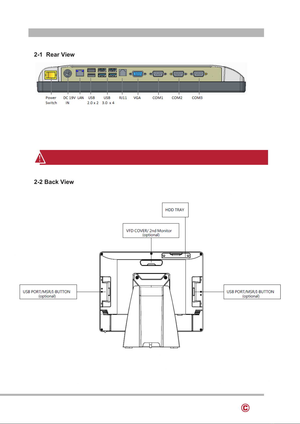
2-1 Rear View 7
2-2 Back View 7
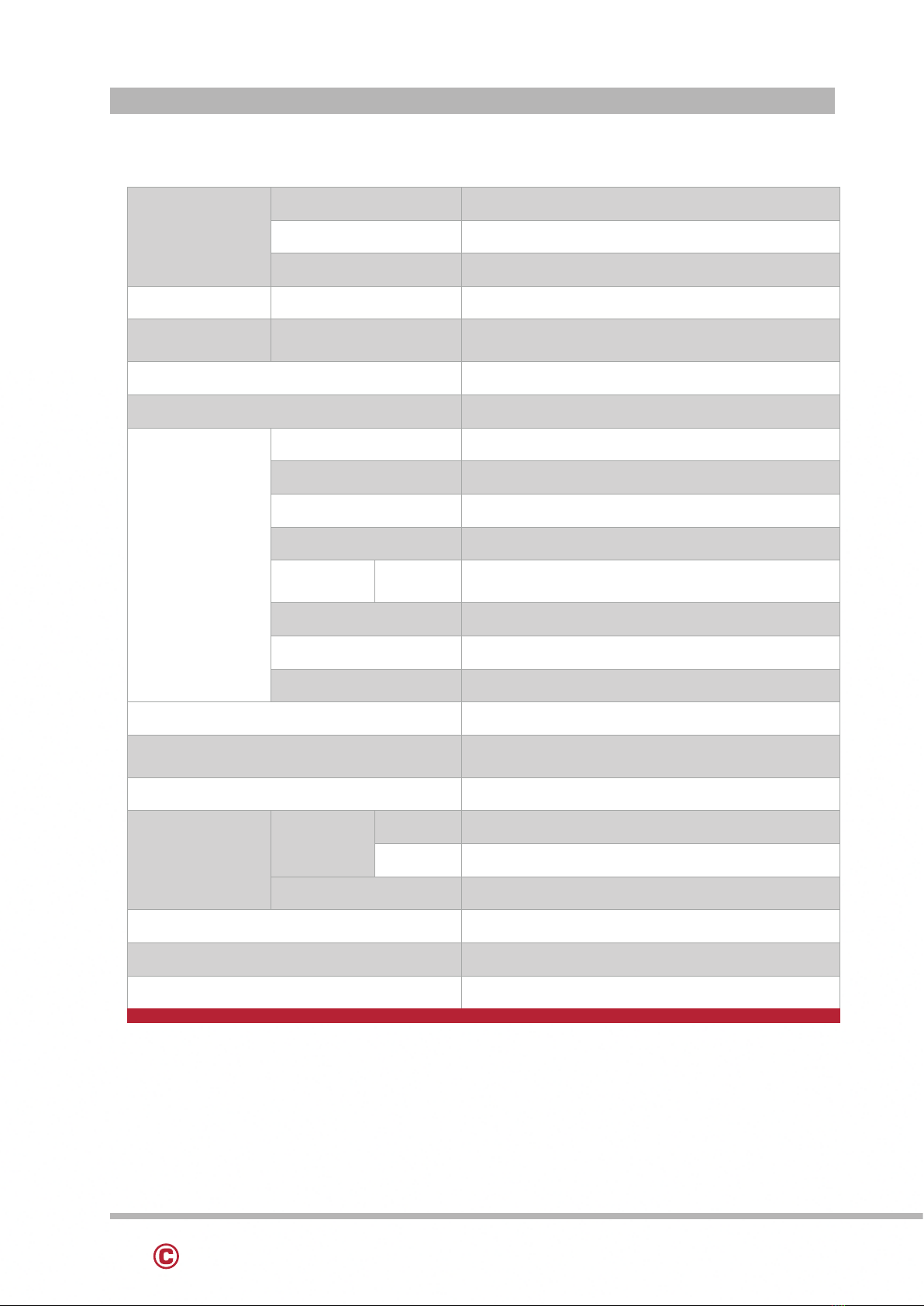
2-3 Specication 8
2-4 Internal Layout 9
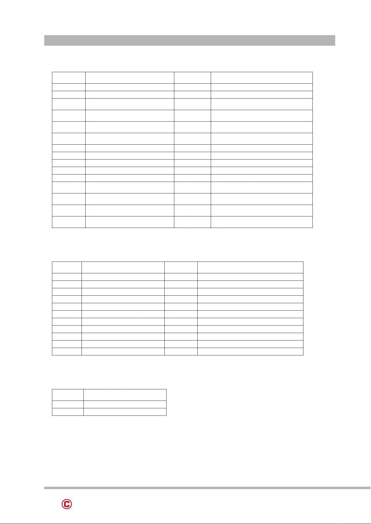
3. PIN DEFINITION 10
4. REAR I/O INTERFACE 12
5. SYSTEM ASSEMBLY & DISASSEMBLY 15
5-1 HDD/SSD 15
5-2 RAM 16
5-3 MSR / i-Button / RFID 17
5-4 VFD / 8”/ 9.7” 2nd Display 18
5-5 1D/2D Barcode Scanner 19
6. DEVICE DRIVER INSTALLATION 20
6-1 MagSwipe Card Reader /i Button reader Conguration utility 20
6-2 Install framework 4.0 26
6-3 VFD 28
7. TOUCH UTILITY SETUP 33
8. BIOS/UTILITY SETUP 35
7-1 Advanced 37
7-1-1 Boot Conguration 38
7-1-2 Audio Conguration 39
7-1-3 Video Conguration 40
7-1-4 SATA Conguration 41
7-2 Security 42
7-3 Power 43
7-4 Boot 44
7-5 Exit 45
8. LCD SURFACE CLEANING 46
TABLE OF CONTENTS