ColorVerse ColorVibe 108 User manual

Model: CV108
®

TABLE OF CONTENTS
2.
PRODUCT INFORMATION
Unpacking your fixture
Photometrics
Product dimensions
Specifications
Safety precautions
Product features
BluControl™ software features
Product overview
DMX PRIMER
Understanding DMX512
Working with DMX controllers
Assigning a DMX start address
Types of controllers
Understanding controller vs. fixture channels
Grouping fixtures
DMX address overlap
INSTALLATION
Mounting the fixture
Safety cable
Clamps
DMX linking
DMX signal polarity
DMX cabling tips
Powering your fixture
OPERATING INSTRUCTIONS
Getting started
BluControl™ menu map basic (default settings)
BluControl™panel basics
BluControl™ panel in detail
High temperature protection
DMX channel protocol
Creating custom colors
Creating great whites
16 bit dimming delay
Master / Slave mode
About macros
Troubleshooting
Maintenance / Fuse Replacement
Warranty & Returns
3.
3.
3.
4.
4.
5.
5.
6.
7.
7.
7.
7.
8.
9.
9.
10.
10.
10.
11.
11.
12.
13.
14.
15.
16.
18.
22.
23.
24.
24.
25.
26.
26.
28.
30.
31.
©2010-2014 Colorverse, Inc. - All Rights Reserved: All information contained within this manual including
drawings and photographs are copyrighted property of Colorverse, Inc.
®

3.
©2010-2014 Colorverse, Inc. - All Rights Reserved
10.5
26.7m
8.75
22.23cm
12.25
31.1cm
11.25
28.6cm
12.25
31.1cm
16.5
41.9cm
15.75
40.1cm
This fixture has been thoroughly tested and shipped in proper working condition. Upon arrival check the contents of
your package and make sure there is no damage due to shipping. If you discover damage, contact the shipping
company immediately, then contact Colorverse® Lighting. We recommend you test your new fixture prior to installation.
If you find damage or failure, this will eliminate the need to uninstall the fixture. In the event your fixture may need
warranty work, you will need to return it in adequate packaging. For this reason, we recommend you do not discard the
box and packing material. Failure to ship the fixture back in proper packaging can potentially void warranty.
IF YOU ARE NEW TO DMX LIGHTING, we recommend that you read the section ‘DMX Primer’ in this document. This
information will help you to better understand many of the topics discussed within this manual. Please read this entire
manual prior to operating your fixture.
WHAT’S INCLUDED:
- One ColorVibe™108 Fixture
- One locking AC power cable
- One steel safety cable with D-ring
Always install the included safety cable
This chart shows how the beam will spread at varying distances
from the fixture. Beam angle refers to the angle between the
two planes of light where the intensity is 50% of the maximum
intensity at center beam.
Standard
Lux measurements at 100% rgb
25° Medium Wash Beam Angle
PHOTOMETRICS
UNPACK AND INSPECT YOUR FIXTURE
1m (3.28 ft)
22,900 lux
3m (9.84 ft)
3430 lux
0m
.5m (1.7 ft) 1.4m (4.3 ft)
PRODUCT DIMENSIONS
®

4.
©2010-2014 Colorverse, Inc. - All Rights Reserved
SPECIFICATIONS
High-output 36 x 3-watt RGB LEDs, 108 watts total
Locking input/output power connectors for daisy-chain power link (8 fixtures max.)
Metal DMX input/output connectors
Wide stance, dual-yoke handle doubles as a floor stand for uplighting
Lux: 22,900 @ 1m | 3430 @ 3m
Medium beam angle: 25° (Opt. 15°, 45°) Field angle: 42°
LED lifespan 100,000 hours (to >75% luminous, figures obtained by manf. tests)
Power: 120V, 60Hz | Current: 120W, 1 Amp operating
AC power: Auto switching 100V-240V 50/60Hz
Weight: 6.5 lbs, 2.9Kg | Size: 10.5 in x 8.75 in
IP20 Ingress protection, indoor use only
BluControl™Operating Software
Ultra smooth 16-bit dimming (zero dimming-jitter or scan issues)
Variable speed fan circuit for long fan-life and near silent operation
LCD display panel for easy address and mode changes
High-temperature protection circuit, to extend lamp life (with F° temp display)
3, 5, or 8 DMX channel mode options
Stand alone programs: Auto Color, Gradual Fade, Audio
DMX controllable mic sensitivity
Hours-of-use timer
Global calibration of red, green, blue intensity
In/Out lockable power connectors for power-linking fixtures
®
SAFETY PRECAUTIONS
WARNING: Do not look directly into the lighting fixture which may cause eye injury and/or epileptic seizures
This fixture is designed for indoor use only, do not expose to moisture or submerge in liquid
Do not attempt to open and service or alter this fixture, while under warranty this light should only be serviced
or repaired by a authorized Colorverse Lighting repair technician
Installation of the fixture should only be completed by a qualified person in accordance with related local codes
A periodic safety inspection should be completed to assure all hardware is secure and mounting is safe for use
Improper installation can result in serious bodily injury
Do not mount in areas where unauthorized persons can handle or manipulate this fixture
Make sure the mounting surface or truss can adequately support the fixture prior to mounting
This fixture must have a secondary safety device installed (such as the included safety cable) properly rated
for this fixture
Be sure to have a qualified electrician perform all electrical connections
Complete all installation procedures prior to plugging in power cord
Keep fixtures away from flammable objects by at least 2 feet (.6 meters)
Do not Power-Link more than (8) fixtures in a single chain (8 amperes max)ColorVibe™108
Disclaimer: Colorverse, Inc. makes efforts to ensure information in this manual is accurate, however it makes no
guarantee or warranty of this information and assumes no liability arising from misinformation contained within. This
manual may be updated without notice to the user.

5.
©2010-2014 Colorverse, Inc. - All Rights Reserved
The ColorVibe™108 is an LED par 64 equipped with more pro-level features than any other in its price range – 16 bit
dimming, LCD display, locking in/out power connectors, and variable speed fan, just to name a few. It’s loaded with
36 x 3-watt RGB lamps, boasting more than 22,000 lux. The ColorVibe™108will get the job done – without breaking
your wallet.
The 25° degree optics produce a medium-wash (optional 15° or 45°) making this fixture the right choice for a variety
of applications such as: band stages, houses of worship, theaters, nightclubs, and architectural lighting. The wide
stance, dual-yoke handle makes uplighting easy, with plenty connector clearance due to the long and stable handle
design. Attention to small details like high temperature protection, metal DMX connectors, internal locking nuts and
safety cable (included) will ensure many years of safe and reliable operation.
Locking Power Connectors
This is a pro-level feature you wont find on many LED pars – Lockable input/output power connectors with the
ability to daisy-chain power your fixtures (up to 6 fixtures on one chain).
Dual Yoke Floor Stand
Equipped with dual yoke for stable floor-stand operation when uplighting is needed. With plenty clearance for
cable management.
PRODUCT FEATURES
®
Developed by Colorverse , BluControl™ is the brain of our intelligent lighting fixtures. Extremely powerful with
many advanced functions, it’s amazingly easy to use. All Colorverse stage pars are equipped with BluControl™,
so learn to navigate the software on any Colorverse fixture and you’ll instantly be familiar with all our fixtures.
Intelligent lighting – simplified.
16-bit Dimming
In the past, traditional halogen pars have had an advantage over most LED pars when it comes to smooth
dimming and cross-fading. This is due to the fact that halogen pars use analogue dimming, and most LED pars
use a digital 8-bit digital dimming processor. Since there are only 256 increments of dimming with 8-bit, you can
see jittering artifacts when dimming. This is especially evident when the dimming is close to off (values 000 - 025)
We’ve solved that problem with our new 16-bit dimming processor. With thousands of incremental dimming steps,
the ColorVibe™108produces butter-smooth dimming and cross-fades that rival the analogue halogen pars. Also,
we’ve added a dedicated ‘Dimming Delay’ channel. You’ll find this feature useful for dramatic, time-delayed ‘fade
off’, ‘fade on’ and ‘cross-fades’. See the chapter in this manual entitled 16 Bit Dimming for more information about
this feature.
LCD
The BluControl™liquid crystal display provides more information and is much easier to read than the 4-digit
displays you’ll find on most LED pars. Changes to modes and addresses is a breeze.
Variable Speed Fan
The advanced fan circuit offers three options: AUTO (default), LOW and HIGH. The fan velocity can range from
silent to high volume cooling. Other benefits are extended fan life, long lamp life and reduced need for regular
cleaning, due to dust and smoke debris build up.
High-Temperature Protection
This valuable feature included in BluControl™ will ensure the long life of your LED lamps and protect from
overheat failure and color degradation. The over-sized heat sink temperature can be monitored in the display
“Temp” mode at any time.
Color Calibrate
A near infinite colors can be created directly form the fixture with no need for a DMX controller.
Load Defaults
This convenient option recalls the factory defaults in one step.
BluControl™Software Features
®

PRODUCT OVERVIEW
6.
©2010-2014 Colorverse, Inc. - All Rights Reserved
®
BluControl™
LCD Display
Dual yoke
Yoke adjustment knob
Knob clutch washer
Locking power output
DMX input
DMX output
Safety cable attachment bracket
*Ventilation input ports
DMX Signal Presence Indicator
Locking power input
Fuse holder
*Ventilation output
*WARNING: Do not place the fixture face down (LED lamps) on a flat surface.
This will block the airflow and cause fixture overheating.

7.
©2010-2014 Colorverse, Inc. - All Rights Reserved
UNDERSTANDING DMX512
DMX512 is a universal protocol for digital communication used to control lighting systems. It allows all DMX equipped
lighting fixtures (from different manufactures) to all operate together using a “common language”. The DMX controller is the
‘brain’ of the network and is used to send instructions to the fixtures through a DMX cable. This allows the lighting director
to control all of the fixture’s features from a single location (via the DMX controller). The value range for each DMX channel
is always 000 (off) - 255 (full on). There are a total of 512 DMX channels per universe. Most lighting networks contain only
one universe, however complex systems can contain several universes each with 512 channels.
The DMX network consists of a controller, multiple fixtures, and is always wired in a "series" style chain. The controller
connects to the fixture 1 "In-connector" then the fixture 1 "Out-connector" plugs into the fixture 2 "In-connector" and so on...
In the example below, the 4 fixtures will operate independent of each other since they all have unique “start addresses” 001,
017, 033, 049 (start address is covered in the next section).
WORKING WITH DMX CONTROLLERS
DMX Controller
Always use a 120 ohm 1/4w
DMX terminator on the
last fixture in the chain
001 017 033 049
In Out In Out In OutOut
Fixture 1 Fixture 3 Fixture 4Fixture 2
DMX PRIMER
ASSIGNING A FIXTURE’S “START ADDRESS”
In order for a DMX controller to communicate with fixtures, each fixture must be assigned a DMX “start address”. This is the
numerical address in which the corresponding fixture will listen to the controller. There are 512 available starting addresses.
You assign the start address to each fixture by using the control panel (on each fixture). Before you can set the starting
address on your fixtures, you must determine what starting addresses are available on your controller.
Types of Controllers
Most hardware-based controllers have preset starting addresses for each fixture button and cannot be changed. However, if
you are using a software-based controller, you should be able to choose your starting addresses for each fixture or fixture
group (fixture grouping covered in next chapter). The drawing below illustrates a typical hardware-based controller with
preset starting addresses.
Keep in mind it does not matter the order of the fixtures within the chain. The DMX start address 001 does not have to be the
first address in the chain. It can be at the start, the middle or the end.
You can also assign the same starting address to multiple
fixtures - called “Grouping Fixtures” (see drawing example on the next page). This will allow those fixtures to work as a group
and they will all respond the same to controller commands.
If you assign each fixture with a unique start address,
the controller can operate the fixtures independent of each other.
234
15 6
Hardware-based DMX controller
If you are using a hardware-based DMX controller, you will need to refer to its operation
manual to determine the preset starting addresses for each fixture button. In this
example, the controller has 16 available channels for each fixture. So the starting
addresses are simply ( )add 16 ( ) add 16 ( ) add 16 ( ) and so on.001 017 033 049
001 017 033 049 065 081 and so on... (starting addresses)
®

8.
©2010-2014 Colorverse, Inc. - All Rights Reserved
UNDERSTANDING “CONTROLLER CHANNELS” VS. “FIXTURE CHANNELS”
It can be confusing to understand the difference between a controller’s channels, the fixture’s channels and the
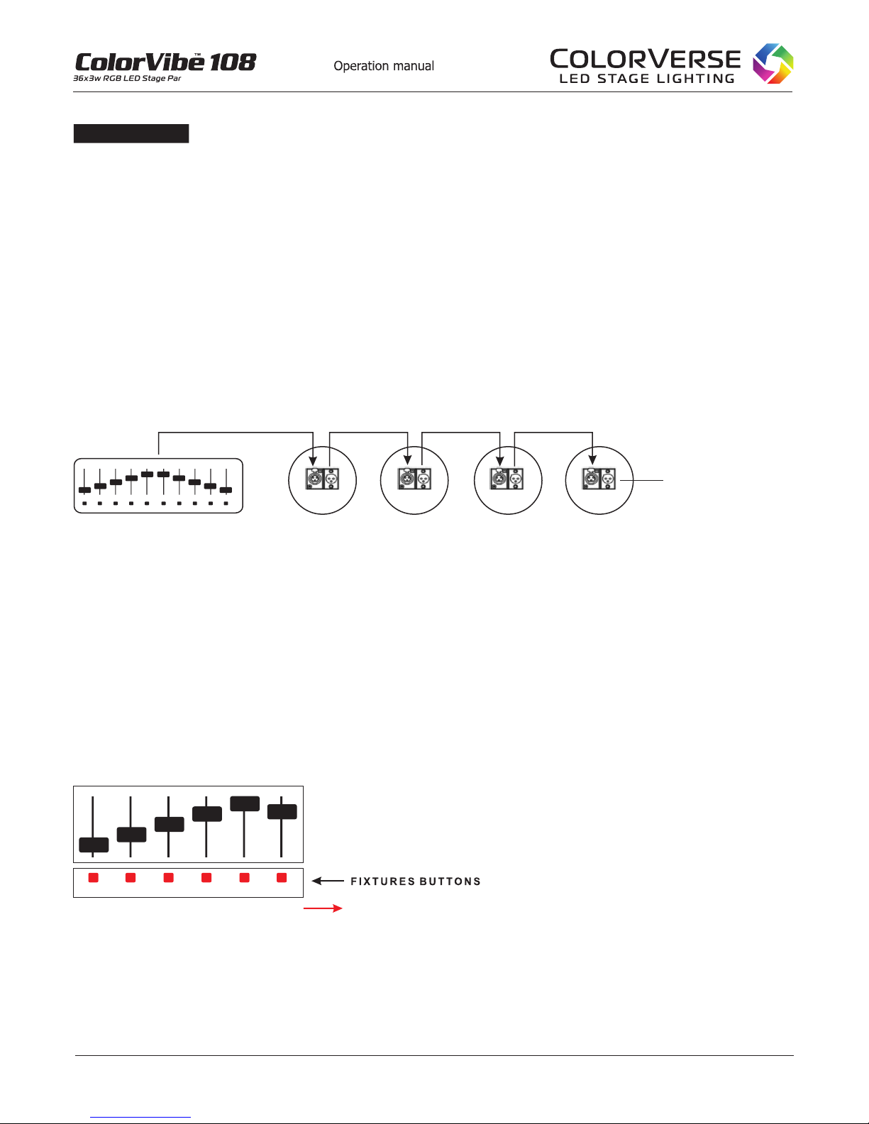
relationship of both. Hardware based DMX controllers typically allocate a group of channels per fixture. For example,
a 192 channel controller will allocate 16 channels per fixture, for 12 fixtures maximum. (16 x 12 = 192). This means
each fixture button on the controller can control up to 16 channels within a given fixture (or fixture group). Lighting
fixtures also have channels, referred to as “fixture channels” (e.g. 1 - Dimmer, 2 - Red, 3 - Green, 4 - Blue, etc).
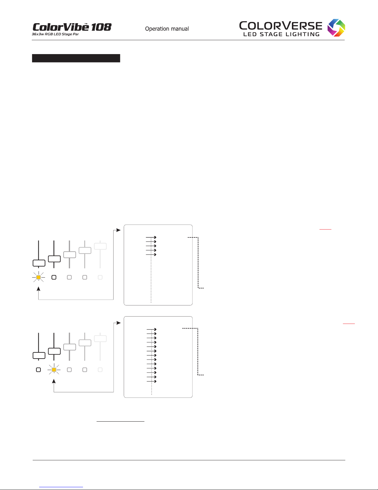
Example: Lets say we are using a hardware-based controller with 16 (channels) x 12 (fixtures) , and we want to
use a par 64 stage light that has only 5 fixture channels (1. Dimmer, 2. Red, 3. Green, 4. Blue, 5. Strobe), the
remaining 11 controller channels are not used within that fixture button, they are wasted (see drawing example below).
Conversely, if you try to operate a moving head fixture containing 24 channels, you will not be able to control all the
fixture channels with a 16 channel controller. Channels 17 - 24 will be unusable with this 16 channel controller, you
will need to use a controller with 24 (or more) “controller channels” per fixture (such as a software-based controller).
Software-based controllers allow complete custom mapping of channels/fixtures to avoid unused controller channels
described above. Software-based controllers are the most flexible regarding this issue and allow you to allocate the
number of controller channels you need per fixture. Please refer to the drawing below and reread this chapter if you
are not clear on the difference between fixture channels vs. controller channels. You will need to know the
difference before you can build your DMX network of lights.
With fixture button 1 depressed, the controller’s faders
will control all aspects of the fixture assigned to fixture
1. In this case, start address 001. This controller
allows up to 16 channels to be used on each fixture,
however this par 64 light only uses 5 fixture channels,
therefore channels 6 - 16 go unused.
Note: Fixture channel 1 (Dimmer) corresponds to
controller channel 1. Fixture channel 2 (Red)
corresponds to controller channel 2 ...and so on.
With fixture depressed, the controller’s faders
will control all aspects of the fixture assigned to fixture
2. In this case, start address 017. Since the moving
head in this example uses only 13 fixture channels,
there are 3 unused channels on the controller (14 - 16)
Note: Fixture channel 1 (Pan) corresponds to controller
channel 17. Fixture channel 2 (Pan fine) corresponds
to controller channel 18...and so on.
button 2
12345
F I X T U R E S
Ch 1.
Ch 2.
Ch 3.
Ch 4.
Ch 5.
Ch 6.
Ch 7.
Ch 8.
Ch 9.
Ch 10.
Ch 11.
Ch 12.
Ch 13.
Ch 14.
Ch 15.
Ch 16.
Dimmer
Red
Green
Blue
Strobe
.
unused
unused
unused
unused
unused
unused
unused
unused
unused
unused
unused
Example 1 - Par 64,
Start Address 001
Ch 1.
Ch 2.
Ch 3.
Ch 4.
Ch 5.
Ch 6.
Ch 7.
Ch 8.
Ch 9.
Ch 10.
Ch 11.
Ch 12.
Ch 13.
Ch 14.
Ch 15.
Ch 16.
FIXTURE
CHANNELS
CONTROLLER
CHANNELS
>
12345
F I X T U R E S
Ch 1.
Ch 2.
Ch 3.
Ch 4.
Ch 5.
Ch 6.
Ch 7.
Ch 8.
Ch 9.
Ch 10.
Ch 11.
Ch 12.
Ch 13.
Ch 14.
Ch 15.
Ch 16.
Pan
Pan fine
Tilt
Tilt fine
Speed
Dimmer
Red
Green
Blue
Macros
Vector
Movement
Gobos
.
unused
unused
unused
Example 2 - Moving Head,
Start Address 017
Ch 17.
Ch 18.
Ch 19.
Ch 20.
Ch 21.
Ch 22.
Ch 23.
Ch 24.
Ch 25.
Ch 26.
Ch 27.
Ch 28.
Ch 29.
Ch 30.
Ch 31.
Ch 32.
FIXTURE
CHANNELS
CONTROLLER
CHANNELS >
F A D E R S
F A D E R S
DMX CONTROLLERDMX CONTROLLER
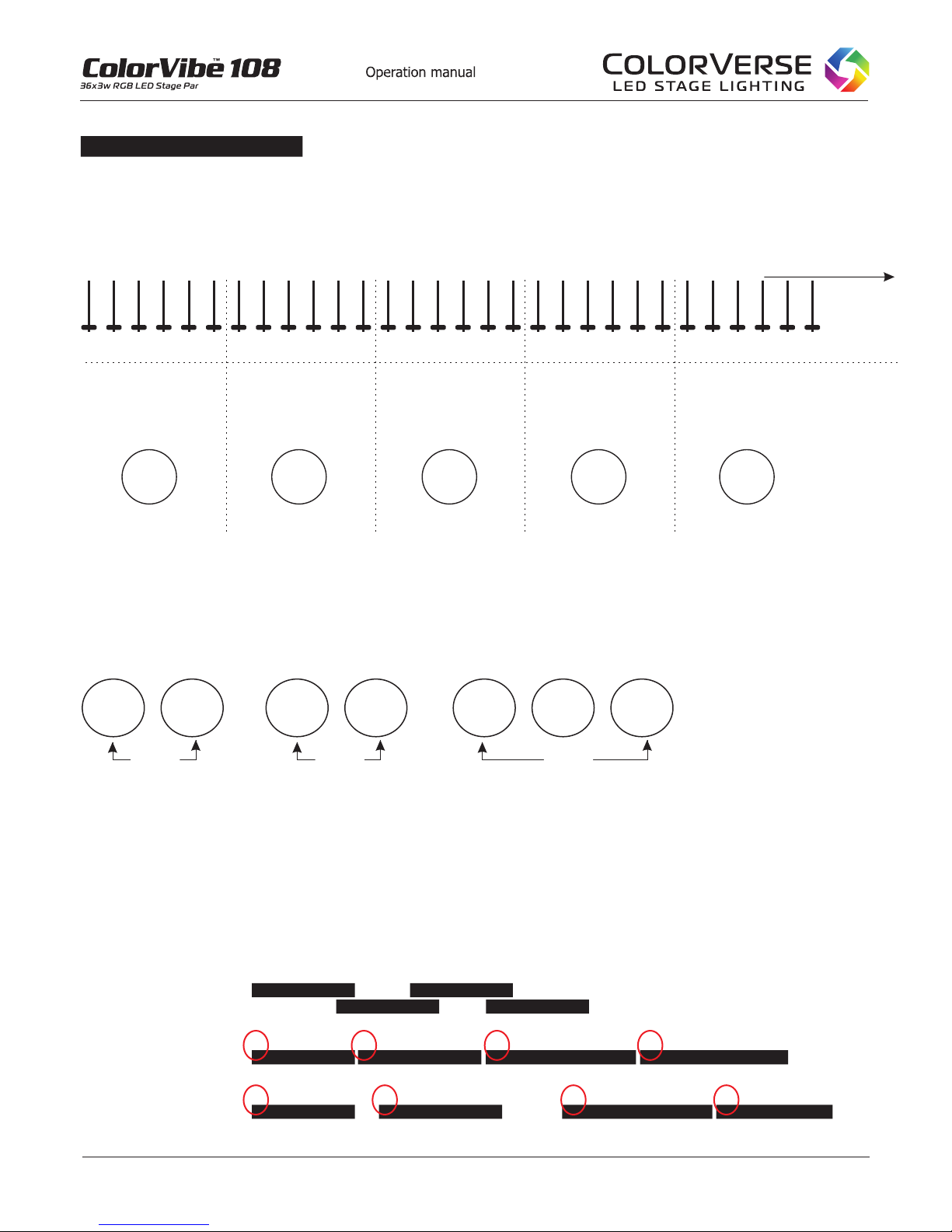
If we were to continue this example, the next fixture (#3) would start at address 33....and so on. Just remember
that each fixture button on your controller will have an assigned group of channels that will correspond to the
available channels in each fixture. You must refer to your controller’s manual to determine the start address for
each fixture. Exception: Software based controllers offer custom mapping of the start addresses, so there are no
wasted channels as there are when using a hardware based controller.
DMX PRIMER (continued)
®

9.
©2010-2014 Colorverse, Inc. - All Rights Reserved
Group 3
Group 1
In this example, the lights in each group will respond to the controller with the same action (notice the in the drawing).red start address
033
Group 2
001 001 033 033
017 017
DMX ADDRESS OVERLAP
X
DMX Start Address
(Overlappng)
FIXTURE 1
Correct
DMX Start Address
1 2 69
8
7
5
43 14
10 12 19 23
2120
17
1615
13
11 18 22
24 >>
FIXTURE 2
FIXTURE 3
FIXTURE 4
FIXTURE 1
1 2 69
8
7
5
43 14
10 12 19 23
2120
17
1615
13
11 18 22 24 >>
FIXTURE 2 FIXTURE 3 FIXTURE 4
GROUPING FIXTURES
Acceptable
DMX Start Address
FIXTURE 1
1 2 69
8
7
5
43 14
10 12 19 23
2120
17
1615
13
11 18 22 24 >>
FIXTURE 2 FIXTURE 3 FIXTURE 4
1.
2.
3.
Never allow your DMX starting addresses to overlap the preceding or subsequent fixture. For example, if your par fixtures have 6
channels, your starting address should always be separated by at least 7 controller channels. In the drawing below, example #1 is
incorrect and will result in errors and erratic behavior of your lighting fixtures. Example #2 and #3 are correct (you can have unused
controller channels if you wish as in example #3)..
The red numbers in the drawing below represent the DMX channels in a controller (512 channels max).
DMX lighting systems can be configured in many ways. The most basic network could be a group of Par lights all with a starting
address of 001. In this case, all 8 lights would operate as one (unison). If you wish to control them individually, you must assign
each fixture its own unique starting address. However, in many systems you will operate groups of lights with a common
starting address for each group as in the example below.
1 2 3 4 5 6 7 8 9 10 11 12 13 14 15 16 17 18 19 20 21 22 23 24 25 26 27 28 29 30
UNDERSTANDING “CONTROLLER CHANNELS” VS. “FIXTURE CHANNELS” (continued)
The drawing below offers a linear view of the relationship between the controllers DMX channels and the fixtures DMX channels
and why each fixture needs a ‘Start Address’. In the example below we are using a par 64, with 6 fixture channels, controlled
by a software-based controller (allowing custom mapping of start address).
Continues up to 512
A001
1 Dimmer
2 Red
3 Green
4 Blue
5 Strobe
6 Macros
A007
Controller
Channels
Fixture 1
starting address 001
1 Dimmer
2 Red
3 Green
4 Blue
5 Strobe
6 Macros
Fixture 2
starting address 007
A013
1 Dimmer
2 Red
3 Green
4 Blue
5 Strobe
6 Macros
Fixture 3
starting address 013
A019
1 Dimmer
2 Red
3 Green
4 Blue
5 Strobe
6 Macros
Fixture 4
starting address 019
A025
1 Dimmer
2 Red
3 Green
4 Blue
5 Strobe
6 Macros
Fixture 3
starting address 025
Fixture
Channels
DMX PRIMER (continued)
®

©2010-2014 Colorverse, Inc. - All Rights Reserved 10.
®
Always install the included safety cable when mounting your fixture in an overhead location or anywhere a mounting
failure could cause injury to person or property damage. To install, loop the safety cable around the mounting truss or
other secure mounting point and attach the D-ring clip to the anchor point on the top of your fixture (see images below).
The safety cable provides a redundancy to the primary mounting clamp/hardware in the event it were to fail. All
overhead and wall installations should be performed only by qualified professionals. We recommend a thread-locking
compound on threaded bolts as an extra precaution to ensure that the fixture installation is secure and safe.
Safety Cable
INSTALLATION
Safety cable
WARNING: Incorrect installations can result in personal injury or death, or damage to
property. Do not mount the fixture in the ventilation path of a nearby heating supply duct, the
heated airflow may cause fixture failure due to overheating. Do not place the fixture face down
(LED lamps) on a flat surface.
Mounting the Fixture
This fixture can be mounted in any orientation or angle. Always make sure there is adequate ventilation and no
flammable surfaces within 2 feet (.6 meters) of the fixture. DO NOT PLACE THE FIXTURE FACE DOWN (LED
lamps) on a flat surface, this will cause overheating due to airflow restriction. You can mount the fixture using fixture
clamps or with threaded bolt type hardware. Always install the included safety cable when mounting in overhead or
wall locations (see images below for reference).
Ventilation output
Ventilation
input
ports
Do not place the fixture face down (LED lamps) on a flat surface, this will restrict the airflow and cause overheating.

11.
©2010-2014 Colorverse, Inc. - All Rights Reserved
Colorverse® fixtures operate on “PIN 3 positive polarity” (refer to the diagram above). If your fixtures are not working
or operating erratically, it is possible your controller’s polarity switch is not set correctly. Refer to the operation manual
of your controller for more information about this issue. It a good idea to place a small piece of tape over the switch to
prevent accidental change to the polarity during transport or operation.
Polarity switch commonly found on hardware-based controllers. Set to “Pin 3 positive” setting.
DMX fixtures are always wired in a ‘series’ style wiring chain. Using a DMX signal cable, t
In a typical DMX chain you can install up to 16 fixtures. Connecting more than 16 fixtures in a single chain will
increase the likelihood of data errors (due to signal degradation along the chain). For lighting shows larger than 16
fixtures, you should create multiple chains using a ‘DMX optical splitter’ or use wireless transmitter/receivers. Either
method will allow you to create multiple chains and maintain a clean error-free signal path in your DMX lightning
network. Maximum length of DMX signal cabling per
chain should not exceed 200 ft.
See DMX Cabling Tips Chapter for more information.
he DMX controller
connects to the first fixture’s ‘DMX input’ then fixture 1 ‘DMX Output’ plugs into fixture 2 ‘DMX Input’ and so on (see
drawing above).
Always use a DMX terminator on the last fixture in the chain.
DMX LINKING
1
3
2
COMMON
DMX +
DMX -
DMX Terminator:120 Ohm 1/4 watt resistor
Pins 2 & 3
1
3
2
DMX SIGNAL POLARITY
DMX Controller
In Out In Out In Out
Out
Fixture 1 Fixture 3 Fixture 4Fixture 2
DMX terminator
In
Connecting your fixtures with DMX cable
®

Do not use XLR audio microphone cables for your lighting fixtures. While microphone cables use the same type of
connector, they are not compatible. Microphone cables are designed to work with analogue audio signals, while
DMX cables are specifically designed for digital data transfer. When troubleshooting DMX lighting, one of the most
common problems will be with cabling. Below are a few tips that will help ensure clean, error-free data flow
throughout your DMX network.
Controller
DMX
Terminator
DMX
Terminator
DMX Optical Isolated Splitter
Recommend no more than 16 fixtures per chain
?
?
?
?
?
?
?
?
?
?
Always use a high quality, professional grade DMX cable
Always use the shortest DMX cable possible for each light fixture within the chain
Do not allow excessive tension on DMX cable or connectors
When using wire ties to secure DMX cable, do not over tighten and pinch the cable
Keep DMX cables away from electromagnetic sources such as power cables, motors, etc
Do not allow kinks or excessive twisting to occur in the DMX cable
Do not split a DMX chain with a “Y-Splitter” use an ‘Optical Isolated DMX splitter’ only
Do not connect more than 16 fixtures within a single chain, use an *optical isolated DMX splitter and
create additional chains (to prevent signal degradation) or use a wireless system like the diagram below
Always use a DMX terminator on the last fixture in a chain
NEVER use audio microphone cables for DMX lighting
EXAMPLE: Typical DMX network with Optical Isolated Splitter
EXAMPLE: Typical DMX network using a wireless system
Controller Transmitter
DMX
Terminator
DMX
Terminator
Recommend no more than 16 fixtures per chain
Receiver
Receiver
DMX CABLING TIPS
©2010-2014 Colorverse, Inc. - All Rights Reserved 12.
®

13.
©2010-2014 Colorverse, Inc. - All Rights Reserved
POWERING YOUR FIXTURE
The ColorVibe™108 is equipped with in/out locking power connectors. These connectors are designed to securely
hold your fixture's power cord in place. See the instructions below to properly insert and remove the connector.
Another advantage is the ability to power-link your fixtures. Power-linking is simply a daisy chain of power cables
from one fixture to the next, eliminating the need to use power strips.
TO INSERT:
1. Line up the tabs on the male connector and insert
2. Twist clockwise to lock
TO REMOVE:
1. Pull back the metal locking tab on the male connector
2. Turn counter-clockwise and pull out the plug
®
Example of lockable power jumper cables (not included)
- Use only high-quality, 14 or 16 gauge AWG, 3-conductor power cables
Do not use 18 guage or smaller power cables, electrical overload may occur
- Blue connector is ‘Power In’, Grey connector is ‘Power Out’
WARNING: DO NOT POWER-LINK MORE THAN (8) COLORVIBE 108 FIXTURES IN ONE SINGLE CHAIN,
(8 AMPERES MAXIMUM) ELECTRICAL OVERLOAD MAY OCCUR. USE SUPPLIED POWER CABLES ONLY.
POWER-JUMPER CABLES MUST BE RATED 14 AWG OR 16 AWG, DO NOT USE 18 AWG OR SMALLER.
Power-Link Your Fixtures
Using the included power cable, connect the 3-prong Edison style plug into a grounded power outlet. Plug the
blue end of the cable into the blue ‘Power Input’ on the first fixture in the chain. Fixture 1 now has power.
Continue the power-link chain by connecting a ‘power-jumper’ cable from Fixture 1 ‘Power Out’ grey connector,
into Fixture 2 ‘Power Input’ blue connector. Connect subsequent fixtures with ‘power jumper’ cables for a
maximum of (8) ColorVibe 108 fixtures per power-link chain. Never exceed more than 8 amperes per chain.
Power input cable (included)
Power Out Power In Power Out Power In
Power In

GETTING STARTED
If you are new to DMX lighting, please read this page. It will help avoid common mistakes and many troubleshooting
headaches.
There are two basic options to operate your DMX fixtures:
1. DMX Address Mode - must have a system of DMX cables
2. Auto Mode - can operate independently or use a system of DMX cables (if using a Master/Slave configuration)
1. DMX Address Mode
This is the most common mode in which DMX fixtures are operated. You must use some type of DMX controller for
this mode. Each fixture must have a DMX starting address (see chapter ‘DMX Primer” for more details about
Starting Address) and all fixtures must be connected with DMX cables.
2. Auto Mode includes
If you choose to operate your fixtures in Auto Mode, do not use a DMX controller. You can operate each fixture
independently without the need for connecting DMX cables, or connect them in a Master/Slave configuration (see
chapter Master/Slave).
Please note! You cannot use a DMX controller and operate any fixture in Auto / Audi / Color mode within the
same network (system of cables). This will cause errors and prevent your system form operating correctly.
Example incorrect configuration:
Auto / Audi / Color (sometimes referred as Stand Alone Mode)
DMX Controller
001 017 033 AUTO
In Out In Out In OutOut
Fixture 1 Fixture 3 Fixture 4Fixture 2
In the example above, fixture 4 is in Auto Mode, while fixtures 1, 2, 3 are in DMX Address Mode. This will cause
errors in the system.
With DMX fixtures you must choose to operate in either DMX address Mode, or Auto Mode (this includes
Auto/Audi/Color). See the next chapter ‘Global Defaults for an overview of BluControl software modes and
settings.
™
DMX Address Mode or Auto Mode (stand alone)
or
X
Fixture 4 should
be in Address Mode
14.
©2010-2014 Colorverse, Inc. - All Rights Reserved
®

15.
©2010-2014 Colorverse, Inc. - All Rights Reserved
Values for Speed, Mic Sensitivity, Auto, Audi and Color modes are not available
when using a DMX controller. These modes are for stand-alone use only.
Address
001-512
Speed
001 - 031
Auto
Mode 0
Mode 1
Mode 2
Audi
Mode 0
Mode 1
Mode 2
Mode 3
Color
Red
Green
Blue
Yellow
Magenta
Cyan
White 1
White 2
White 3
Time
00000
Color Calibr
Red Calibr
001-255
Green Calibr
001-255
Blue Calibr
001-255
(001 default)
(008 default)
(default)
(default)
(default )
(240 default)
(240 default)
(240 default)
Channel Mode
3 ch.
5 ch.
8 ch.
Dimmer Mode
Instant
Delay
Key Mode
Lock
UnLock
DMX Status
Value
Clear
Hold
Display Mode
Auto
On
Fan Mode
Auto
Low
High
(default)
(default)
(default)
(default)
(default)
(default)
Load
Default
Yes
No
Config
Temp
000F°
BluControl™MENU MAP and DEFAULT SETTINGS
®

16.
©2010-2014 Colorverse, Inc. - All Rights Reserved
The chart below is a global view of the Main Modes, Sub Modes and the Value options. See next chapter ‘Control
Panel Details’ for more information about these functions.
Please note that the values for Speed, Mic Sensitivity, Auto, Audi and Color modes are not available when
using a DMX controller. These modes are for stand-alone use only.
To choose a main mode:
Press Up or Down,
Press ENTER to select the mode,
Press Up or Down to choose a sub menu or value for the selected mode,
Press ENTER to activate
DMX ADDRESS
MODE: VALUE:
Use this mode to set the DMX start address for each fixture
This mode adjusts the speed (001 fastest - 031 slowest) of the
Auto Modes. This setting also adjust the internal mic sensitivity
for Audi Mode (when using the fixture without a controller).
001 is most sensitive, 031 is least sensitive.
AUTO COLOR
Auto - Gradual Color Fade (full color spectrum)
SOUND ACTIVATE
Auto - 9 Color Change
Auto - 3 Color Change
Sound Activated Cross-fade Color Change
Sound Activated 9 Color Change
Sound Activated 3 Color Change
STATIC COLOR
OPERATION TIMER
Sound Activated Strobe Color Change
Choose from one of preset static colors
See chapter ‘Creating custom colors” for information
on more color options
SPEED / MIC SENS
BluControl™PANEL Basics
®
Hours of operation timer. The timer accrues if power when
applied even if the light is not on.

17.
©2010-2014 Colorverse, Inc. - All Rights Reserved
BluControl™PANEL Basics (continued)
®
CALIBRATION
This adjusts global output of the colors separately.
Changes to this mode will override the DMX controller
commands to the fixture.
CONFIGURATION
This setting leaves the control panel unlocked.
This setting will hold the last scene if the DMX signal
is interrupted (controller crash, unplugged cable, etc).
Note: This mode can be used to create custom
colors, see chapter “Creating Custom Colors”.
LOAD DEFAULT
This will load the default settings as it came from the factory.
This setting locks the control panel after 30 seconds
of inactivity. Press ESC key for 2 seconds to unlock
This setting will black-out the fixture (go dark) if the
DMX signal is interrupted (controller crash, unplugged
cable, etc).
Display
Mode
Fan
Mode
This setting will automatically turn off the display after 10
seconds of inactivity.
This setting will leave the display on.
This setting will allow the fan to operate at variable speeds,
depending on the fixture and ambient temperatures. This mode
will offer near silent operation.
This setting will allow the fan to operate at continuous low speed
and is a good option where low-fan noise is critical. Do not use this
mode in high ambient temperatures or when it is necessary to
operate the fixture at high outputs for long periods.
This setting will allow the fan to operate at maximum speed
regardless of the fixture and ambient temperatures. This mode
is recommended when operating your fixture in high temperature
locations or where fan noise is not an issue.
Low
High
This is a global setting that changes colors instantly for a
staccato effect.
This is a global setting that changes colors with a 500ms delay
which simulates a traditional par.
This Mode selects how many DMX channels are operational
within the fixture. 8 channel mode allows you to use all the
features available (see chapter “Channel Mode in Details”).

18.
©2010-2014 Colorverse, Inc. - All Rights Reserved
®
Address: DMX ADDRESS MODE
See the section ‘DMX Primer’ in this document for more
information about DMX Addressing.
Press UP or DOWN until you see Address ***
Press ENTER, the display will now read: Set Add ***
PUP or DOWN
Speed: SPED/MIC SENSITIVITY MODE
This setting serves a dual function;
1. If you are in Auto Mode, this setting controls the speed at which colors change.
001 - the fastest, and 031 the slowest.
2. If you are using Audi sound activation mode, this setting controls the Mic Sensitivity.
001 - the most sensitive, and 031 the least sensitive.
To change the Speed Rate or Mic Sensitivity,
Press UP or DOWN until you see SPED/MIC,
Press ENTER, then choose between values: 001 - 031
Press ENTER to store
Note: After making changes to the SPED/MIC setting, you must press ESC and “re-enter” Auto Mode
or Audi Mode to activate the changes.
Title: When using a DMX controller, the mic sensitivity can be adjusted with the Macro channel..
Auto: AUTO COLOR MODE
This mode is an internal program that changes color automatically at varying speeds. This mode can only be used
without a DMX controller, please disconnect your controller before activating Auto Color Mode.
To enter Auto Color Mode,
Press UP or DOWN until it shows Auto,
Press ENTER, press UP or DOWN to choose one of 3 sub-modes below,
- Auto 0: Gradual Color Fade through the entire color spectrum
- Auto 1: Change through primary and secondary colors
- Auto 2: Change through primary colors
Press ENTER to store
Note: The rate of change can be adjusted in the Speed mode. See Speed Mode chapter above.
Audi: SOUND ACTIVATION MODE
The internal microphone activates color changes based on sound. This mode can only be used without a DMX
controller. Bass frequencies offer the best results (continued on next page).
This mode is used to set the ‘start address’ for this fixture and is the most commonly used mode for DMX lighting.
You must use some type of DMX controller when operating in this mode. Check the manual for your DMX controller
to determine the recommended start address for each fixture.
To set the DMX start address for this fixture,
ress until you reach the desired DMX address,
Press ENTER to store, then ESC to return to DMX address mode
¤
¤
¤
BluControl™PANEL in detail
Note: The LCD display will automatically turn off after 10 seconds of inactivity, press ESC to activate the display.
ESC DOWN UP ENTER
With the display active, notice the green LED at the top right.
There are three modes to this indicator:
Blinking: indicates the fixture is: 1. Address mode and 2. is receiving a DMX signal
Off: indicates the fixture is: 1. in Address mode and 2. is not receiving a DMX signal
Solid: indicates the fixture is not in Address mode, but is in Auto, Audi, Color etc.
This indicator is a useful feature when troubleshooting.

19.
©2010-2014 Colorverse, Inc. - All Rights Reserved
Audi: SOUND ACTIVATION MODE (continued from previous page)
To enter Sound Activation Mode,
Press UP or DOWN until you see Audi,
Press ENTER, press UP or DOWN to choose one of these 4 sub-modes:
- Mode 0: Cross-fading colors
- Mode 1: 9 color (Red, Green, Blue, Yellow, Magenta, Cyan, Wht 1, Wht 2, Wht 3)
- Mode 2: 3 color (Red, Green, Blue)
- Mode 3: Color strobe effect
Press ENTER to store
Color: STATIC COLOR MODE
This mode allows you to choose one of the static colors. This mode can only be used without a DMX controller,
please disconnect your DMX controller before choosing Static Color Mode.
To enter Static Color Mode,
Press UP or DOWN until you see Color,
Press ENTER,
Press UP or DOWN to choose colors,
Press ENTER to store
Time: OPERATION TIMER
This mode displays the amount of hours the fixture has been in operation. The timer accrues if power is applied even if the
light is not on. This is useful to determine how often the fan may need cleaning. In some environments (that use fog or
cigarette smoke), the fan may need cleaning every 300 hours. The fan should only be cleaned by an authorized
professional repair facility. Risk of electrical shock, injury or death may occur.
Color Calibr: COLOR CALIBRATE
This mode allows you to globally calibrate the intensity of each color: Red, Green, Blue or Amber. For example, if your
green lamps are too bright at 100% (relative to the other colors) you can reduce the intensity in this mode. Changes to this
mode affect all color mixing at the controller.
Note: If you reduce the intensity of any color to 000, you will not be able to activate that color channel on your controller.
These settings are global and override the controller. See ‘Creating Custom Colors’ chapter for more info.
Note: It is recommended to leave the maximum intensity at 240 which will extend the life of the LED lamps.
To enter Color Calibrate Mode,
Press UP or DOWN until you see Color Calibr,
Press ENTER,
Press UP or DOWN to choose color,
Press ENTER,
Press Up or Down to change the value 000 (off) to 255 full intensity (240 is recommended),
Press ENTER to store the setting,
Press ESC then Up or Down to choose another Color and repeat the above directions
Finally, press ESC again to exit Color Calibr and enter another mode of your choosing
Note: Most commonly the Color Calibr mode is used to create custom colors for use without a DMX controller.
See chapter “Creating Custom Colors” for more information.
¤
¤
¤
BluControl™PANEL in detail (continued)
®

20.
©2010-2014 Colorverse, Inc. - All Rights Reserved
CHANNEL MODE:
DIMMER MODE:
This is a global setting that allows the fixture to change colors with a quick cross-fade effect.
This is a global setting that allows color changes to be instant.
KEY MODE:
This setting leaves the control panel unlocked.
This setting locks the control panel after 30 seconds of inactivity. Press ESC for 2 seconds
to unlock.
*Unock
Lock
DMX STATUS MODE:
This setting will hold the last scene if the DMX signal is interrupted (controller crash, cable issue, etc.).
This setting will black-out the fixture (go dark) if the DMX signal is interrupted.
3 Channel
Utilizes (4) DMX channels
on your controller
1: Red
2: Green
3: Blue
1: Dimmer
2: Red
3: Green
4: Blue
5: Strobe
5
Utilizes (6) DMX channels
on your controller
Channel
*Delay
Instant
*Hold
Clear
Config: CONFIGURATION MODE
This mode allows you to make global changes to the fixture. There are six sub-modes:
Channel Mode, Dimmer Mode, Key Mode, DMX Status Mode, Display Mode, Fan Mode
To enter Configuration Mode,
press UP or DOWN until you see Config,
press ENTER,
Press UP or DOWN to choose one of six sub-modes,
press ENTER, the press Up or Down to change the values within the sub-mode,
Press ENTER and now press ESC two times and re-enter your desired operating mode
¤
1: Dimmer
2: Red
3: Green
4: Blue
5: Strobe
6: Macros (see Macro chapter)
7: Macro Speed
8: Dimming Delay
*8
Utilizes (9) DMX channels
on your controller
Channel
DISPLAY MODE:
This setting will automatically turn off the display after 10 seconds of inactivity.
This setting will leave the display on.
*Auto
On
FAN MODE: continued on next page
* The asterisks above indicate the default setting.
BluControl™PANEL in detail (continued)
®
Table of contents