ComAp IG-NTC User manual

Copyright © 2006-7 ComAp s.r.o.
ComAp, spol. s r.o.
Světova 7, 180 00 Praha 8, Czech Republic
Tel: +420 266 790 611, Fax: +420 266 316 647
Technical support hotline: +420 266 790 666
USER GUIDE
Compact Controller for Stand-by and Parallel Operating Gen-sets
Inteli New Technology
Modular Generator Controller
Multiple Internal engines application – SW configuration
MINT - GeCon
IG-NT, IG-NTC, IG-EE, IG-EEC
Software version IGS-NT-GeCon-1.4, June 2007

Inteli NT GeCon MINT, SW Version 1.4, ©ComAp – June 2007
IGS-NT-GeCon-MINT-1.4.PDF
2
Table of Contents
Table of Contents ...............................................................................................................................................2
General guidelines..............................................................................................................................................3
What is described in this manual? .................................................................................................................3
General description ............................................................................................................................................5
Description of the controller system (with all options)....................................................................................5
Comparing of IG-NT-GeCon-1.3 to the standard IG-NT-MINT-2.0................................................................5
Available documentation ................................................................................................................................5
Functions ............................................................................................................................................................6
Modified setpoints ..........................................................................................................................................6
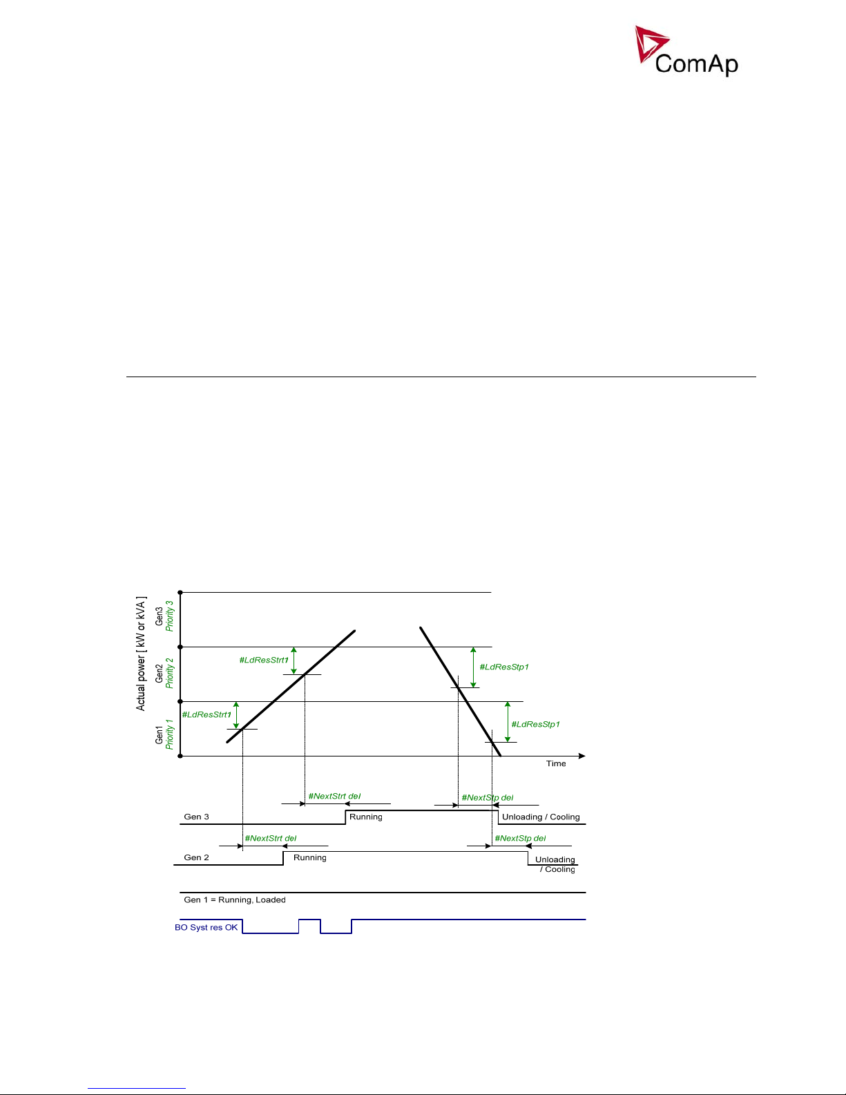
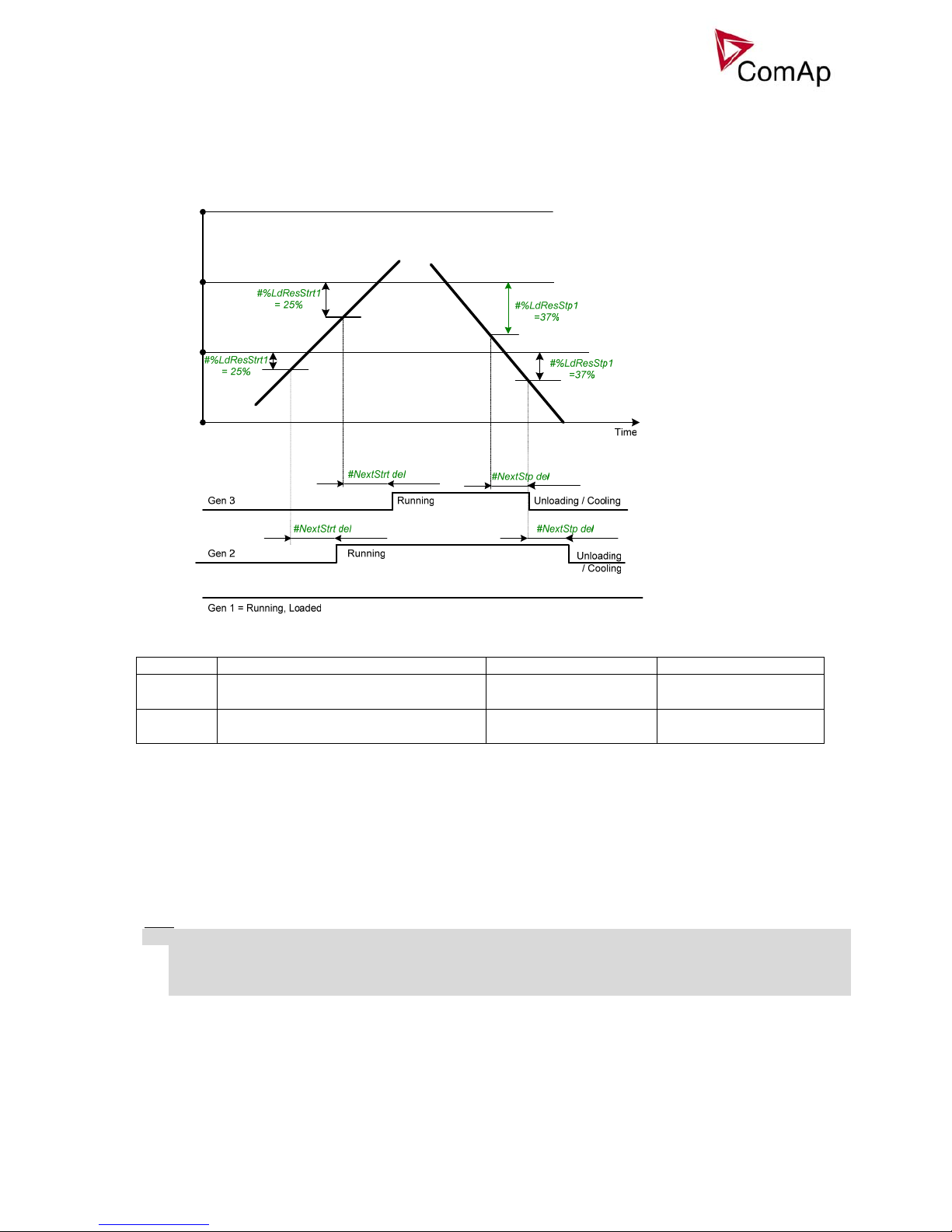
Power management .......................................................................................................................................8
PLC functions ...............................................................................................................................................14
Multi language support.................................................................................................................................14
Protections and Alarm management ................................................................................................................15
Gen-set operation states ..................................................................................................................................18
Inputs and Outputs ...........................................................................................................................................19
Virtual and physical modules .......................................................................................................................19
Binary Inputs - Control .................................................................................................................................19
Binary inputs – Status information ...............................................................................................................24
Binary outputs – Breaker control..................................................................................................................24
Binary outputs – Control loops.....................................................................................................................25
Binary outputs – Status information .............................................................................................................26
Binary outputs – Fixed protection outputs....................................................................................................28
Binary outputs – Configurable prog. States .................................................................................................30
Binary outputs – Power management..........................................................................................................32
Analog inputs................................................................................................................................................33
Analog outputs .............................................................................................................................................33
Analog values...............................................................................................................................................33
Setpoints...........................................................................................................................................................34
ProcessControl.............................................................................................................................................34
Basic settings ...............................................................................................................................................39
Engine protect ..............................................................................................................................................43
Analog protect ..............................................................................................................................................46
Gener protect ...............................................................................................................................................46
Pwr management .........................................................................................................................................52
Sync/Load ctrl...............................................................................................................................................56
Volt/PF ctrl....................................................................................................................................................59
Force value...................................................................................................................................................61
Load shedding..............................................................................................................................................62
Timer settings...............................................................................................................................................63
Act. calls/SMS ..............................................................................................................................................63
Date/Time.....................................................................................................................................................65
Controller configuration and monitoring ...........................................................................................................66
Direct connection to the PC .........................................................................................................................66
GenConfig functions.....................................................................................................................................66
InteliMonitor..................................................................................................................................................67
Modbus protocol...........................................................................................................................................67
Value and setpoint codes.............................................................................................................................67
Technical data..............................................................................................................................................67

Inteli NT GeCon MINT, SW Version 1.4, ©ComAp – June 2007
IGS-NT-GeCon-MINT-1.4.PDF
3
General guidelines
What is described in this manual?
This manual describes IGS-NT-GeCon - „MINT“ software configuration. The Generator controller software
configuration is designed for multiple sets applications with internal load sharer and synchronizer.
What is the purpose of this manual?
This manual provides general information on how to configure and operate the controller.
This manual is intended for use by:
Operators of gen-sets
Gen-set control panel builders
For everybody who is concerned with installation, operation and maintenance of the gen-set
!! Warnings !!
Remote control
The IG-NT controller can be remotely controlled. In case that maintenance needs to be done to the gen-set,
check the following to ensure that the engine cannot be started.
To be sure:
Disconnect remote control via RS232 line
Disconnect input REMOTE START/STOP
or
Disconnect output STARTER and output GCB CLOSE/OPEN
The controller contains a large number of configurable setpoints, because of this it is impossible to describe
all of its functions. These are subject to change from SW version to SW version. This manual only describes
the product and is not guaranteed to be set for your application on arrival.
Text
PAGE (Capital letters in the frame) buttons on the front panel
Break Return (Italic) set points
Generator protections (Bold) Set point group
REMOTE START/STOP (Capital letters) binary inputs and outputs
Cyan background Valid for IS-NT only
Conformity declaration
Following described machine complies with the appropriate basic safety and health
requirement of the EC Low Voltage Directive No: 73/23 / EEC and EC
Electromagnetic Compatibility Directive 89/336 / EEC based on its design and type,
as brought into circulation by us.
Note:
ComAp believes that all information provided herein is correct and reliable and reserves the right to update
at any time. ComAp does not assume any responsibility for its use unless otherwise expressly undertaken.

Inteli NT GeCon MINT, SW Version 1.4, ©ComAp – June 2007
IGS-NT-GeCon-MINT-1.4.PDF
4
WARNING – VERY IMPORTANT !!!
Be aware that the binary outputs can change state during and after software
reprogramming (before the controller is used again ensure that the proper
configuration and setpoint settings are set in the controller)!!!
Be aware that gen-set can automatically or remotely start !!!
Switch the controller to MAN mode and disconnect the Binary outputs Starter and Fuel
to avoid unexpected automatic start of gen-set and GCB closing.
!!! CAUTION !!!
Dangerous voltage
The terminals for voltage and current measurement should never be touched.
Properly connect the grounding terminals.
Do not disconnect the CT terminals for any reason.
Adjust set points
All setpoints are preadjusted to their typical values. But the set points in the “Basic settings” settings
group !!must!! be adjusted before the first startup of the gen-set.
!!! WRONG ADJUSTMENT OF BASIC PARAMETERS
CAN DESTROY THE GEN-SET !!!
The following instructions are for qualified personnel only. To avoid personal injury do
not perform any action not specified in this User guide !!!

Inteli NT GeCon MINT, SW Version 1.4, ©ComAp – June 2007
IGS-NT-GeCon-MINT-1.4.PDF
5
General description
Description of the controller system (with all options)
NT Family controllers are comprehensive AMF-controllers for single and multiple generating sets operating
in stand-by or parallel modes. A modular construction allow upgrades to different levels of complexity in
order to provide the best solution for various customer applications.
NT Family controllers are equipped with a powerful graphic display showing icons, symbols and bar-graphs
for intuitive operation, which sets, together with high functionality, new standards in Gen-set controls.
The controller automatically starts the gen-set, closes the Gen-set C.B. when all conditions are met, then
stops the engine on external signal or by pressing push buttons.
Parallel to the Mains operation is a standard feature. Isolated parallel and Power Management System
support are optional. Forward and reverse synchronizing, Generator protections, Mains protection including
vector shift, load and power factor control are the major functions provided. Interfacing to foreign
synchronizers and load sharers is supported.
The key feature of the controller is its easy-to-use operation and installation. Predefined configurations for
typical applications are available as well as user-defined configurations for special applications.
Comparing of IG-NT-GeCon-1.3 to the standard IG-NT-MINT-2.0
•GeCon does not take care of Engine control – option adjustable by setpoints.
•GeCon does not directly control GCB – option adjustable by setpoints.
•GeCon accepts external – “by hand” Engine and GCB control.
•GeCon can control the engine via Binary start/stop output signals only – see below. The independent
Engine controller (e.g. ID-DCU) is expected.
•Synchronizing and unloading timeouts can be disabled by setpoint setting (or Force value function).
•Interface GeCon to engine controller is provided by I/O wires no by communication line.
Available documentation
IGS-NT-Application guide-2.1.pdf
IGS-NT-Installation guide-2.1.pdf
IGS-NT-Operator guide-2.1.pdf
GenConfig-2.1.pdf
InteliMonitor-2.1.pdf
Application examples.
All modules wiring.
Brief panel buttons, display handling guide.
PC configuration tool guide.
PC monitoring tool guide.

Inteli NT GeCon MINT, SW Version 1.4, ©ComAp – June 2007
IGS-NT-GeCon-MINT-1.4.PDF
6
Functions
The IGS-NT-LSM+PMS dongle enables the Load sharing and Power management functions.
Modified setpoints
Below mentioned are GeCon specific setpoints only.
Group Setpoint Option Function
StartStopBtn ENABLED
DISABLED
Standard panel Start/Stop buttons function.
Panel Start/Stop buttons are disabled.
Process control
ProtectionMode ACTIVE
NOT ACTIVE
Standard MINT function.
2-nd level protections are blocked.
Sync timeout 1-1800s
NO TIMEOUT
Standard MINT function.
Unlimited synchronizing time.
GCB open level 1-100%
NO LEVEL
Standard MINT function.
No generator power open level detection.
Sync/Load ctrl
GCB open del 1-1800s
NO TIMEOUT
Standard MINT function.
Unlimited unloading procedure.
Hint:
All setpoints can be Forced by Binary input(s) to another value (or switched between ENABLED and
DISABLED).
Based on setpoint settings there are three possible operational modes HAND – MAN - AUT:
“HAND” MAN AUT
Basic setting ControllerMode MAN MAN AUT
StartStopBtn DISABLED ENABLED ENABLED
Process control ProtectionMode NOT ACTIVE ACTIVE ACTIVE
Sync timeout NO TIMEOUT 1-1800s 1-1800s
GCB open level NO LEVEL 1-100% 1-100%
Sync/Load ctrl
GCB open del NO TIMEOUT 1-1800s 1-1800s
Hint:
It is possible to configure (Force value) “HAND” – MAN switching via Binary input.
OFF mode
Use OFF mode to block controller functions (even if is switched on). OFF mode is used for controller
firmware or configuration change.
Binary outputs (e.g. GCB CLOSE/OPEN) are not energized, all closed Binary outputs are opened when
controller is switched to OFF mode.
Gen-set cannot be started and operated from IG-NT-GeCon controller – no response for panell buttons and
Binary input commands.
Hint:
Switching to OFF mode is blocked on running engine to avoid accidental engine stop by mode change or by
firmware or configuration programming.

Inteli NT GeCon MINT, SW Version 1.4, ©ComAp – June 2007
IGS-NT-GeCon-MINT-1.4.PDF
7
HAND mode
IG-EE GeCon
MINT
MCU
GCB feedback
GCB
close/open
Vg, Ig, Vb
RS232 - PC
Speed control
(Sync/Load ctrl)
GCB
START
STOP
(ReadyToLoad)
GG
External Engine
Start / Stop
External GCB
Close / Open
generator
measuring
Process control: StartStopBtn = DISABLED
ProtectionMode = NOT ACTIVE
Sync/Load ctrl: Sync timeout = NO TIMEOUT
GCB open level = NO LEVEL
GCB open del = NO TIMEOUT
MCU
MAN mode
IG-EE GeCon
MINT
MCU
RS232 - PC
GCB
START
STOP
(ReadyToLoad)
G
GCB close/open
Remote start/stop
System s/s
G
Vg, Ig, Vb
Generator measuring
Process control: StartStopBtn = ENABLED
ProtectionMode = ACTIVE
Sync/Load ctrl: Sync timeout =
GCB open level =
GCB open del =
GCB feedback
Speed control
(Sync/Load ctrl)
Engine Start / Stop
is activated from GeCon
or externaly
GCB Close / Open is
activated from GeCon
or externaly
MCU
Engine start can be activated from
oEngine controller (e.g. ID-MCU)
oGeCon panel – Start button
oGeCon BI: StartButton
oRemotely e.g. from InteliMonitor
GeCon BI: ReadyToLoad initiates GeCon “Running” state” - activates Gener protect: Min stab time a Max
stab time within the generator electric protections are activated.
Gen-set is loaded/unloaded from
oGeCon panel – GCB button
oGeCon BI: GCBButton
oDirect GCB “hand” control
oRemotely e.g. from InteliMonitor

Inteli NT GeCon MINT, SW Version 1.4, ©ComAp – June 2007
IGS-NT-GeCon-MINT-1.4.PDF
8
GCB closing from controller can be blocked by BI: GCB disable.
AUT mode
Engine start or Power management is activated from GeCon BI: Sys start/stop
GeCon BI: ReadyToLoad initiates GeCon “Running” state” - activates Gener protect: Min stab time a Max
stab time within the generator electric protections are activated.
Gen-set starts synchronizing and is loaded/unloaded automatically based on
oPower management setting
oGeCon BI: Sys start/stop
GeCon will stop engine started from MCU when BI Sys start/stop or due to Power management function.
Power management
Automatic gen-set start / stop function based on load changes and/or Running hours or Engine size.
Following functions are available:
Power management in kW
Guarantees adjustable load reserve (load step) in kW. Suitable for load demand-based optimization.
Activation: #Pwr mgmt mode = ABS (kW)
Power management in kVA
Guarantees adjustable load reserve (load step) in kVA. Suitable for generator- or busbar dimensioning-
based optimization.
Activation: #Pwr mgmt mode = ABS (kVA)

Inteli NT GeCon MINT, SW Version 1.4, ©ComAp – June 2007
IGS-NT-GeCon-MINT-1.4.PDF
9
Relative power management in %
Guarantees that the engines be not continuously loaded more than to a certain level, leaving less than
selected relative load reserve. Suitable for engine life-based optimization.
Activation: #Pwr mgmt mode = REL (%)
Gen1
Priority 1 Gen2
Priority 2 Gen3
Priority 3
Actual power [ kW or kVA ]
Start/Stop conditions in Power management
Reserve Actual Reserve Start condition Stop condition
Absolute
kW / kVA
ARstrt = ΣPgNom – ΣPgAct
ARstp = ΣPg*Nom – ΣPgAct
ARstrt < #LdResStrt ARstp > #LdResStp
Relative
%
RRstrt = (ΣPgNom – ΣPgAct) / ΣPgNom
RRstp = (ΣPg*Nom – ΣPgAct) / ΣPg*Nom
RRstrt < #%LdResStrt RRstp > #%LdResStp
Where
ARstrt Actual Absolute reserve in kW or kVA - for engine start calculation.
ARstp Actual Absolute reserves in kW or kVA - for engine stop calculation.
RRstrt Actual Relative reserve in % - for engine start calculation.
RRstp Actual Relative reserves in % - for engine stop calculation.
ΣPgNom Sum of Nominal power of all gen-sets on the bus.
ΣPg*Nom Sum of Nominal power of all gen-sets on the bus apart of the one, which is going to be stopped.
ΣPgAct Sum of Actual power of all gen-sets on the bus = system load.
Hint:
Optional functions in absolute or relative Power management are:
- Running hours balancing (equalization),
- Load demand (different size) engines swap and
- Power management of two or more gen-set groups (bus tie support).

Inteli NT GeCon MINT, SW Version 1.4, ©ComAp – June 2007
IGS-NT-GeCon-MINT-1.4.PDF
10
Running hours balancing
The gen-sets priorities are automatically swapped to balance engine running hours. Up to 32 controllers are
supported.
Activation: #PriorAutoSwap = RUN HOURS EQU
Important setpoints: RunHoursBase , #RunHrsMaxDiff
Different sized engines (Load demand) swap
Three running engines (priorities) are swapped based on load demand (one “small” engine runs on “small”
load and swaps to another one “big” engine that runs when load increases).
Activation: #PriorAutoSwap = LD DEMAND SWAP
Important setpoints: #PwrBandContr1, #PwrBandContr2, #PwrBandContr3, #PwrBandContr4,
#PwrBandChngDe.

Inteli NT GeCon MINT, SW Version 1.4, ©ComAp – June 2007
IGS-NT-GeCon-MINT-1.4.PDF
11
Pwr management of splitted group
Important setpoints: Control group, GroupLinkLeft, GroupLinkRight
When a Bus-tie disconnects the gen-set group the Power management can operate separately on each of
them.
G1 G2 G3 G4 G5
LOAD1 LOAD 2
Basic settings:
Contr.addr = 1
Pwr management:
Control group = 1
GroupLinkLeft = 1
GroupLinkRight = 2
BTB
BI Group link
1.controller 2.controller 3.controller 4.controller 5.controller
Basic settings:
Contr.addr = 2
Pwr management:
Control group = 1
GroupLinkLeft = C
GroupLinkRight = C
Basic settings:
Contr.addr = 3
Pwr management:
Control group = 2
GroupLinkLeft = C
GroupLinkRight = C
Basic settings:
Contr.addr = 4
Pwr management:
Control group = 2
GroupLinkLeft = C
GroupLinkRight = C
Basic settings:
Contr.addr = 5
Pwr management:
Control group = 2
GroupLinkLeft = C
GroupLinkRight = C
Control group 2.
Control group 1.
BTB feedback
Load shedding
All LOAD SHED outputs are activated (closed) to trip the unessential load when gen-set goes to island:
a) When GCB is closed after mains fail and gen-set starts in AUT mode.
b) When MCB opens from parallel to mains operation in AUT mode.
c) Before MCB is opened in MAN mode by button.
The load shedding function is active in all controller modes except OFF.
Load shedding has three steps and each step is linked with its own Load shed x binary output. There is only
one load shed level and delay for all three steps as well as recon level and delay. Load shed can only move
from one step to the next, e.g. No LoadShed to LdShed S1 to LdShed S2 to LdShed S3 and vice versa.
If manual reconnection of the load is desired, the AutoLd recon setpoint needs to be disabled (AutoLd recon
=DISABLED) and the MAN load recon binary input needs to be configured.
Rising edge on this input resets the controller to a lower stage, but only if the load is under the Ld recon level
at that moment.
Hint:
If no Load Shedding outputs are configured, there is no record to history and no scrren timer indication of the
activity of this function.

Inteli NT GeCon MINT, SW Version 1.4, ©ComAp – June 2007
IGS-NT-GeCon-MINT-1.4.PDF
12
Load reconnection – automatic -> AutoLd recon = ENABLED
Ld recon del Ld recon delLd recon del
BO Load shed 2
Ld recon level
Gen-set power
BO Load shed 3
BO Load shed 1
opened
opened
opened
Load reconnection – manual -> AutoLd recon = DISABLED
System Base load
Gen-set group is controlled on constant (or adjustable) power. The Baseload value can by changed by
setpoint or via analog input.
Important setpoints: ProcessControl: #SysLdCtrlPtM = BASELOAD; #SysBaseload; SysBaseLdMode.
Local Baseload
Selected gen-set from island or mains parallel running group can be loaded to constant LocalBaseload
value. This engine is taken out from Load sharing and Power management. LocalBaseload value is reduced
only when common group (actual) load is lower than this value.
The gen-sets in the group will try to match their LocalBaseloads (when more than one) based on their
controller addresses, so the first limited would be the one with the highest CAN address. I.e. this function will

Inteli NT GeCon MINT, SW Version 1.4, ©ComAp – June 2007
IGS-NT-GeCon-MINT-1.4.PDF
13
switch-off automatically in one or more controllers if there is not enough load to cover all the requested
LocalBaseloads.
Important setpoints: ProcessControl: LocalBaseload.
System Base power factor
Gen-set group is controlled in mains parallel to keep a constant (or adjustable) power factor.
Important setpoints: ProcessControl: #SysPFCtrlPtM = BASEPF; #SysPwrFactor.
Import-Export
Gen-set group is controlled to keep constant (or adjustable) Import or Export value. The external controller
InteliMains NT must be connected on the CAN2 to control gen-set group kW I/E.
Important setpoints: ProcessControl: #SysLdCtrlPtM = LDSHARING.
Import/Export power factor
Gen-set group is controlled to keep constant (or adjustable) Import or Export power factor.
Important setpoints: ProcessControl: #SysLdCtrlPtM = VSHARING.The external InteliMains NT controller
must be connected on the CAN2 to control gen-set group PF I/E.
Service time alarm
Engine starting procedures
•Independent Engine controller (e.g. InteliDrive) is expected.
•Interface GeCon to InteliDrive is provided by single BI/BO wires (no communication line).
•GeCon does not directly control engine via Starter, Fuel, Ignition – only sends Start request and Stop
requests.
•Automatic engine start/stop is allowed in GeCon - AUT mode when Power management function is
active.
•GeCon does not measure RPM from pickup.
Engine stopping procedures
•Active Generator protection does not stop running engine (except Power management in AUT mode).
•Engine stop command from MCU opens GCB (via BO Ready to load without Unloading).
Engine “running” conditions
•The additional condition to close GCB (start synchronizing) is GeCon BI Ready to load (coming from
MCU) in both MAN, AUT modes.

Inteli NT GeCon MINT, SW Version 1.4, ©ComAp – June 2007
IGS-NT-GeCon-MINT-1.4.PDF
14
PLC functions
Following functions are available in IG-NT-GeCon firmware.
Config item Selection
Available
IG-NT/EE Note
Log Func I.
16
AND, OR
2 to 8 inputs
Log Func II.
2
XOR, RS
2 inputs
Comp Hyst
2
Analog input
Two limits
Binary output
Delay
4
Adjustable rising and falling edge delay or pulse
on edge.
Multi language support
NT Family controllers support up to five Languages that is possible to switch during controller duty. Every
terminal (i.e. Remote display or PC-InteliMonitor) can be switched to different language. Use PC-GenConfig
- Translator tool to translate texts to another language.
Default application archives contain all texts in English only.

Inteli NT GeCon MINT, SW Version 1.4, ©ComAp – June 2007
IGS-NT-GeCon-MINT-1.4.PDF
15
Protections and Alarm management
Protection groups
There are two groups of protections in the controller: fix and customer configurable.
Setpoint group
Analog protections Configurable Analog protect
Generator protections Configurable Gener protect
Mains protections –
should not be used in
MINT application
Configurable Mains protect
Fix protections Fix Engine params,
Gener protect,
Analog protect
Protection types
Because of limited (adjustable) GeCon influence to the Engine and GCB (depends on configuration and
wiring) the GeCon protection system is more focused to fail indication. All Protection types are available
because of IGS-NT system compatibility even if some Protection types has the same result in GeCon (e.g.
BOC, Stp, Sd).
Level Protection
types Abbre
viation Gen-set action Record
1 History record Hst none History only
1 Alarm only Al none Alarmlist only
1 Warning Wrn none Alarmlist and History
2 Off load OfL AUT modes:
Controller opens GCB without soft
unloading, gen-set runs 1 minute at
Nominal RPM. Gen-set state changes to
Running 1 minute after Off load activation.
Controller starts automatically GCB
synchronizing (or closes GCB) when Off
load is deactivated (no fault reset
necessary).
MAN mode:
Controller opens GCB without soft
unloading and the gen-set runs without
load until operator intervention.
All generator protections are active during
Off load duty.
Alarmlist and History
2 Breaker Open
& Cool-down
BOC Controller opens GCB without soft
unloading, gen-set state changes to
Running.
Alarmlist and History
2 Slow stop Stp Soft unloading then the GCB opens, BO:
Stop pulse; the gen-set state changes to
Stopping.
Alarmlist and History
2 Shutdown Sd Controller opens GCB without soft
unloading.
Alarmlist and History
X Sensor fail Fls Can be indicated when Analog input value
is ±6% out of sensor characteristic range.
Fls can optionally activate corresponding
(e.g. Sd) Analog input protection as well.
Alarmlist and History

Inteli NT GeCon MINT, SW Version 1.4, ©ComAp – June 2007
IGS-NT-GeCon-MINT-1.4.PDF
16
Default protections in MINT
Fix – firmware based
Generator: Corresponding setpoints
IDMT overcurrent BOC Basic settings: Nomin current; Gener protect:
2Inom del
IDMT Active power BOC Gener protect: OverldStrtEval; 2POvrldStrtEvDel
Shortcurrent BOC Gener protect: Ishort; Ishort del
Generator voltage: Ug1>, Ug1<,
Ug2>, Ug2<, Ug3>, Ug3<
BOC Gener protect: Gen >V BOC; Gen <V BOC; Gen
V del.
Generator voltage: Ug1>>,
Ug2>>, Ug3>>
Sd Gener protect: Gen >V Sd; Gen V del.
Generator frequency: fg<, fg> BOC Gener protect: Gen >f; Gen <f; Gen V del
Bus:
Bus voltage (limits derived from
generator protections)
- Gener protect: Gen >V BOC; Gen <V BOC; Gen
V del.
Bus frequency (limits derived from
generator protections)
- Gener protect: Gen >f; Gen <f; Gen V del
Default - configurable
Reverse power (UnivState 1) BOC Gener protect: Reverse power; ReversePwr del
Batt <V, Batt >V (UnivState 2) Wrn Analog protect: Batt >V; Batt <V; Batt V del
EarthFaultCurr (UnivState 5) BOC Gener protect: EarthFaultCurr; EthCurr del
Bus voltage and frequency protections - limits and indications
Basic settings:
VoltProtSelect = PHASE-NEUTRAL
Gener protect: Gen >V BOC
Gen <V BOC
Gen >V Sd
Gen V del
Gen >f
Gen <f
Gen f del
Bus V L1-N
Bus freq
Bus V L2-N
Bus V L3-N
Basic settings:
VoltProtSelect = PHASE-PHASE
Gener protect: Gen >V BOC
Gen <V BOC
Gen >V Sd
Gen V del
Gen >f
Gen <f
Gen f del
Bus V L1-L2
Bus V L2-L3
Bus V L3-L1
Bus freq

Inteli NT GeCon MINT, SW Version 1.4, ©ComAp – June 2007
IGS-NT-GeCon-MINT-1.4.PDF
17
Generator voltage and frequency protections - limits and indications
Basic settings:
VoltProtSelect = PHASE-NEUTRAL
Gener protect: Gen >V BOC
Gen <V BOC
Gen V Sd
Gen V del
Gen >f
Gen <f
Gen f del
BOC L1 under
BOC L2 under
BOC L3 under
BOC L1 over
BOC L2 over
BOC L3 over
Gen V L1-N
BOC fg under
BOC fg over
Gen freq
Gen V L2-N
Gen V L3-N
BOC L12 under
BOC L23 under
BOC L31 under
BOC L12 over
BOC L23 over
BOC L31 over
Gen V L1-L2
BOC fg under
BOC fg over
Gen freq
Gen V L2-L3
Gen V L3-L1
Basic settings:
VoltProtSelect = PHASE-PHASE
Gener protect: Gen >V BOC
Gen <V BOC
Gen V Sd
Gen V del
Gen >f
Gen <f
Gen f del
Hint:
Additional protections can be configured using the Protection – Universal states tool. Limits for additional
generator/bus voltage Universal protections are in Phase-Neutral format not depends on Basic settings:
VoltProtSelect setpoint.
Shutdown override
If the Binary input Sd override is closed, all 2nd level protections are disabled to allow engine run in an
emergency situation, e.g. sprinkler devices power supply.
All protections are shown in Alarmlist and recorded into History, but the controller doesn’t stop the engine
because of them. If the input is deactivated and some protections are still active or not yet reset, the
controller starts to take these protections into account and consequently stops the engine.
Hint:
All 2nd level protections are locked out, except of these:
-Emergency stop
-Overspeed
-Underspeed (only if Fuel solenoid = GAS ENGINE)

Inteli NT GeCon MINT, SW Version 1.4, ©ComAp – June 2007
IGS-NT-GeCon-MINT-1.4.PDF
18
Gen-set operation states
Gen-set can operate in following states
Not ready Gen-set is not ready to start
Init After controller power supply switch on
Stopped No Running indication
Starting Waiting for ReadyToLoad signal
Running Waiting for GCB connection or start synchronizing
Soft load Gen-set power is ramping up
Loaded Gen-set is loaded
Soft unld Gen-set power is ramping down
Stopping Stopping procedure before the BI ReadyToLoad is opened.
Stopped Stopped - initial state – waiting for engine start
Breakers conditions
Brks Off GCB opened
Synchro Gen-set is synchronizing (bus voltage OK, GCB is
open)
MultIslOp Multiple Island - gen-set is running loaded in island
parallel mode (MCB is open, GCB is closed)
MultParOp Multiple Parallel – gen-set is running loaded in
mains parallel mode (MCB is closed, GCB is
closed)

Inteli NT GeCon MINT, SW Version 1.4, ©ComAp – June 2007
IGS-NT-GeCon-MINT-1.4.PDF
19
Inputs and Outputs
Virtual and physical modules
Number of I/O can be extended and project wiring can be reduced using the following extension and virtual
modules.
Module name
BIN
BOUT
AIN
AOUT
Note
IGS-NT controller x x x x Number of I/O depends on type.
IGS-PTM 8 8 4 1 Standard I/O extension module.
IS-AIN8 - - 8 - Standard I/O extension module.
IS-BIN16/8 16 8 - - Standard I/O extension module.
I-CB x x x x Configurable communication bridge.
IGL-RA15 - 15 - - 15 Green, Red, Yellow LED panel.
I-AOUT8 - - - 8 8 Analog outputs
VPIO 8 8 - - Virtual periphery I/O module.
SHBIN 8 - - - SHared (virtual) Binary INput module
SHBOUT - 8 - - SHared (virtual) Binary OUTput module
SHAIN - - 4 - Shared (virtual) Analog Input module
SHAOUT - - - 4 Shared (virtual) Analog OUTput module
PLC x x x x Programmable (internal) logic module.
Binary Inputs - Control
AccessLock int
If the input is closed, no setpoints can be adjusted and no commands can be issued from the controller front
panel.
Hint:
As the controller mode (OFF-MAN-AUT-TEST) is one of the setpoints, not even that can be changed.
The START, STOP, FAULT RESET and other control buttons are disabled as well.
AccessLock D#2
If the input is closed, no setpoints can be adjusted and no commands can be issued from IG/IS-Display #2.
AccessLock ext
If the input is closed, no setpoints can be adjusted and no commands can be issued from any external
terminal = via direct/modem/internet connection to the controller.
Hint:
Use these inputs to lock out the selected terminals for setpoint changes and commands. Such a terminal can
only be used for monitoring.
Alt brightness
Active binary input switches controller display backlight to the alternative setting. Alternative intensity of the
backlight can be set independently using the controller panel buttons.
Hint:
Input available in IG-NT/EE and modifications only. For IG-Display and IS-Display modules, this binary input
is located in the Power connector and it’s function is fixed (not configurable).

Inteli NT GeCon MINT, SW Version 1.4, ©ComAp – June 2007
IGS-NT-GeCon-MINT-1.4.PDF
20
FaultResButton
Binary input has the same function as Fault reset button on the controller front panel.
HornResButton
Binary input has the same function as Horn reset button on the controller front panel.
StopButton
Binary input has the same function as Stop button on the controller front panel. It is active in MAN mode
only.
StartButton
Binary input has the same function as Start button on the controller front panel. It is active in MAN mode
only.
GCBButton
Binary input has the same function as GCB button on the controller front panel. It is active in MAN and
TEST modes only. In TEST mode in some special cases only (see description of the TEST mode in chapter
Mode and functions description).
Hint:
All Binary inputs, which simulate controller front panel buttons, are edge (no level) sensitive, and they react
on the rising edge only. Minimal input pulse duration is 0,2 seconds.
Remote OFF
If closed, the controller mode is forced to OFF. When opened controller is switched to previous mode.
Hint:
Use this input to block the engine start during service.
Remote MAN
Active binary input forces the controller mode to MAN.
Remote AUT
Active binary input forces the controller mode to AUT.
Hint:
Use this input to switch the controller to automatic operation, e.g. using the external key switch.
Force block 1 …3
Three binary inputs for user-specific blocking of programmable protections. If the particular input is active, all
the protections with the corresponding “Force block X” block type are blocked.
Force value 1 …16
If any of the particular 16 input s is active, the Force value function on that corresponding channel gets
active, forcing an alternative value to the selected setpoint.
IssueActCallC1 …3
Rising edge on these binary inputs forces an active call to be issued via the corresponding channel.
Hint:
Can be used to send e.g. SMS in the case of a mains failure to report that the engine has successfully
started (linked from the output Gen params OK) and later on to report that the engine has stopped again
(linked from the inverted output Fuel solenoid).
Sys start/stop
If the input closes, the controller may start the engine (in AUT mode only). Request to start depends on state
of setpoint Pwr management: Pwr management state and, if ENABLED, on the actual need of load reserve.
I.e. all controllers in the system should have their Sys start/stop inputs active, but it doesn’t mean that all
engines are running.
This manual suits for next models
3
Table of contents