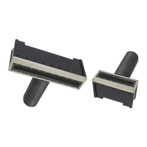
R2Sonic 2026 User manual

SONIC 2026/2024/2022
BROADBAND MULTIBEAM ECHOSOUNDERS
Operation Manual V6.3
Revision 012 (05NOV2022)
Part No. 96000001

Page 2of 254
Version
6.3
Rev
r012
Date
05-11-2022
Part No. 96000001

Page 3of 254
Version
6.3
Rev
r012
Date
05-11-2022
COPYRIGHT NOTICE
Copyright © 2021, R2Sonic LLC. All rights reserved
Ownership of copyright
The copyright in this manual and the material in this manual (including without limitation the text, artwork, photographs,
images, or any other material in this manual) is owned by R2Sonic LLC. The copyright includes both the print and electronic
versions of this manual.
Copyright license
R2Sonic LLC is solely responsible for the content of this manual. Neither this manual nor any part of this manual may be
copied, translated, distributed or modified in any manner without the express written approval of R2Sonic LLC.
Permissions
You may request permission to use the copyright materials in this manual by writing to r2support@r2sonic.com
Authorship
This manual (Sonic 2026/2024/2022 Operation Manual), and all of the content therein, written by:
R2Sonic LLC
5307 Industrial Oaks Blvd, Suite 120
Austin, Texas 78735
USA
Telephone: +1 (512) 891.0000
Version Printing History
•June 2008 Version 1.1/1.2
•July 2008 Version 1.3
•Aug/Sep 2008 Version 1.4
•December 2008 Version 1.5
•June 2009 Version 1.6
•April 2010 Version 2.0
•August 2010 Version 3.0
•April 2011 Version 3.1
•January 2012 Version 4.0
•April 2012 Version 4.1
•February 2014 Version 5.0
•July 2015 Version 6.0 (First version with Sonic 2026)
•June 2016 Version 6.1 (Extended frequency capability and ROBO operation)
•November 2016 Version 6.2 (MultiSpectral Mode™ feature)
•April 2017 Version 6.3 (UHD, MultiMode with PipeTrac™ feature)
R2Sonic LLC reserves the right to amend or edit this manual at any time. R2Sonic LLC offers no implied warranty concerning
the information in this manual. R2Sonic LLC shall not be held liable for any errors within the manual.

Page 4of 254
Version
6.3
Rev
r012
Date
05-11-2022
Part No. 96000001
IMPORTANT NOTICE
Pursuant to the United States Department of Commerce Bureau of Industry and Security Export
rules and regulations, under Export Control Classification Number (ECCN) 6A991 and 6A001, a minor
modification has been made in the range and frequencies available in the R2Sonic Multibeam
Echosounder family only for those systems that are submerged to 100 metres depth or greater.
R2Sonic Multibeam Echosounders now come in either a Standard Spectrum (with the restriction) or
a Full Spectrum (no restriction) version.
The Standard Spectrum system will have the restrictions above apply only when submerged to a
depth greater than 100 metres. A Standard Spectrum system, when submerged to depths greater
than 100 metres, will be restricted to operating frequencies of no less than 350 kHz and ranges no
greater than 200 metres. There are no such restrictions for submerged depths of less than 100
metres or for a Full Spectrum system.
All systems with the Ultra High Density (UHD) feature are considered to be under the same export
restrictions as stated for a Standard Spectrum system.
The R2Sonic Multibeam Echosounders Full Spectrum version have no such modifications but are
subject to possible export control restrictions (please see the local R2Sonic representative for a
clarification of the rules and laws that apply to the country of interest).
The rules and regulations, under which this notice applies, are subject to change at any time and without notice.

Page 5of 254
Version
6.3
Rev
r012
Date
05-11-2022
Table of Contents
1INTRODUCTION ..................................................................................................................23
1.1 Outline of Equipment............................................................................................................ 23
1.2 How to use this Manual........................................................................................................ 24
1.2.1 Standard of Measurement ........................................................................................... 24
2SONIC SPECIFICATIONS .......................................................................................................25
2.1 Sonic 2026 System Specification........................................................................................... 25
2.2 Sonic 2024 System Specification........................................................................................... 25
2.3 Sonic 2022 System Specification........................................................................................... 26
2.4 Sonic 2026 Dimensions and Weights.................................................................................... 26
2.5 Sonic 2024 Dimensions and Weights.................................................................................... 26
2.6 Sonic 2022 Dimensions and Weights.................................................................................... 27
2.7 Sonic 2026/2024/Sonic 2022 Electrical Interface................................................................. 27
2.8 Sonic MBES Ping Rates (SV = 1500.00m/sec) ....................................................................... 27
2.9 Acoustic Centre..................................................................................................................... 29
3SONIC MBES SONAR HEAD INSTALLATION – Surface Vessel .................................................33
3.1 Sonic MBES Receive Module Installation.............................................................................. 33
3.1.1 Mounting the Sonic MBES Receive Module ................................................................. 34
3.1.2 Receive Module............................................................................................................ 34
3.1.3 New Deck Lead connector............................................................................................ 35
3.1.4 New Cable Clamping Arrangement .............................................................................. 36
3.1.5 Mounting the Sonic 2024/2022 Projector.................................................................... 41
3.1.6 Mounting the Sonic 2026 Projector ............................................................................. 42
3.1.7 Correct Orientation of the Sonic MBES ........................................................................ 44
3.1.8 Deck Test Before Deployment...................................................................................... 44
3.2 Sonar Head Installation Guidelines ...................................................................................... 46
3.2.1 Introduction.................................................................................................................. 46
3.2.2 Over-the-Side mount.................................................................................................... 46
3.2.3 Moon Pool Mount ........................................................................................................ 46
3.2.4 Hull Mount.................................................................................................................... 46
3.2.5 ROV Mounting .............................................................................................................. 47

Page 6of 254
Version
6.3
Rev
r012
Date
05-11-2022
Part No. 96000001
4SONAR INTERFACE MODULE (SIM) INSTALLATION and INTERFACING ...................................49
4.1 Sonar Interface Module (SIM)...............................................................................................49
4.1.1 Physical installation.......................................................................................................49
4.1.2 Electrical and Interfacing ..............................................................................................50
4.1.3 Serial Communication...................................................................................................57
4.1.4 Time and PPS input .......................................................................................................57
4.1.5 Motion Input .................................................................................................................58
4.1.6 SVP input .......................................................................................................................58
5OPERATION OF THE SONIC MBES VIA SONIC CONTROL ........................................................60
5.1 Installing Sonic Control Graphical User Interface .................................................................60
5.2 Hot Keys ................................................................................................................................60
5.3 Settings Menu .......................................................................................................................61
5.4 Network Setup.......................................................................................................................61
5.4.1 Initial Computer setup for Communication ..................................................................61
5.4.2 Discover Function..........................................................................................................62
5.4.3 Configuring Network Communication ..........................................................................64
5.5 Sensor Setup (Serial and Ethernet Interfacing) .....................................................................66
5.5.1 Ethernet Interfacing......................................................................................................66
5.5.2 GPS ................................................................................................................................67
5.5.3 Motion...........................................................................................................................67
5.5.4 Heading .........................................................................................................................67
5.5.5 SVP ................................................................................................................................67
5.5.6 Trigger in / Trigger out ..................................................................................................68
5.6 Sonar Settings (Hotkey: F2)...................................................................................................69
5.6.1 Frequency (kHz) 170 kHz – 450 kHz..............................................................................70
5.6.2 Ping Rate Limit ..............................................................................................................71
5.6.3 Sector Coverage ............................................................................................................71
5.6.4 Sector Rotate ................................................................................................................73
5.6.5 Minimum Range Gate (m).............................................................................................73
5.6.6 Bottom Sampling...........................................................................................................73
5.6.7 Ultra High Density (UHD™) ...........................................................................................75

Page 7of 254
Version
6.3
Rev
r012
Date
05-11-2022
5.6.8 Mission Mode............................................................................................................... 77
5.6.9 Imagery......................................................................................................................... 77
5.6.10 Roll Stabilize and Pitch Stabilize ................................................................................... 81
5.6.11 Dual Head Mode (Also see Appendix VII, Section 13.9)............................................... 82
5.6.12 TruePix™, Snippets, Water Column Enable and Intensity Enable ................................ 84
5.6.13 Water Column Data Collection..................................................................................... 85
5.7 MultiMode............................................................................................................................ 86
5.7.1 MultiSpectral Mode™................................................................................................... 86
5.7.2 Pipeline Mode............................................................................................................... 87
5.8 Ocean Setting ....................................................................................................................... 89
5.8.1 Absorption: 0 – 200 dB/km .......................................................................................... 89
5.8.2 Spreading Loss: 0 – 60 dB ............................................................................................. 89
5.8.3 Time Variable Gain ....................................................................................................... 90
5.9 Installation Settings.............................................................................................................. 93
5.9.1 Projector Orientation ................................................................................................... 93
5.9.2 Projector Z Offset (m)................................................................................................... 93
5.9.3 Head Tilt........................................................................................................................ 93
5.10 Status.................................................................................................................................... 94
5.10.1 System Status ............................................................................................................... 94
5.10.2 Saturation Monitor....................................................................................................... 95
5.10.3 TruePix™ Monitor......................................................................................................... 96
5.11 Tools ..................................................................................................................................... 97
5.11.1 Engineering................................................................................................................... 97
5.11.2 Firmware Update.......................................................................................................... 97
5.11.3 Snapshot and Reset Sector Rotate ............................................................................. 100
5.12 Help..................................................................................................................................... 100
5.12.1 Help Topics ................................................................................................................. 100
5.12.2 Options ....................................................................................................................... 100
5.12.3 Remote Assistance ..................................................................................................... 101
5.12.4 About Sonic Control.................................................................................................... 101
5.13 Display settings................................................................................................................... 102

Page 8of 254
Version
6.3
Rev
r012
Date
05-11-2022
Part No. 96000001
5.13.1 US Survey Feet Unit (Display Only) .............................................................................102
5.14 Imagery ...............................................................................................................................103
5.14.1 TruePix™ and Water Column ......................................................................................103
5.14.2 Video Capture .............................................................................................................103
5.15 ROBO Automatic Sonar Operation......................................................................................104
5.15.1 Robo Settings ..............................................................................................................105
5.16 Main Operation Parameters ...............................................................................................106
5.16.1 Range: 0 – 1200 metres ..............................................................................................106
5.16.2 RangeTrac™ – Sonic Control automatically sets correct range ..................................108
5.16.3 Power: 191 – 221 dB ...................................................................................................108
5.16.4 Pulse Width: 15µsec – 1115µsec (Sonic 2026 max is 2000µsec)................................108
5.16.5 Gain: 1 – 45 .................................................................................................................109
5.16.6 Depth Gates: GateTrac™.............................................................................................109
5.17 GUI Rec(ord)........................................................................................................................112
5.18 Ruler ....................................................................................................................................112
5.19 Save Settings .......................................................................................................................113
5.19.1 Default setting ini file..................................................................................................113
5.20 Operating Sonic Control on a second computer .................................................................114
5.20.1 Two computer setup...................................................................................................114
5.20.2 Changing back to one computer.................................................................................115
6SONIC MBES THEORY OF OPERATION................................................................................117
6.1 Sonic MBES Sonar Head Block Diagram..............................................................................117
6.2 Sonic MBES Transmit (Normal Operation Mode)................................................................118
6.3 Sonic MBES Receive (Normal Operation Mode)..................................................................119
6.4 Sonic 2024/2022 Sonar Interface Module (SIM) Block Diagram.........................................121
6.4.1 Sonar Interface Module (SIM) Block Diagram.............................................................121
7Appendix I: R2Sonic I2NS Components and Operation .......................................................123
7.1 Components ........................................................................................................................123
7.1.1 Type 82 IMU................................................................................................................124
7.2 Connection diagram............................................................................................................125
7.3 Installation ..........................................................................................................................126

Page 9of 254
Version
6.3
Rev
r012
Date
05-11-2022
7.3.1 The IMU and GPS antennas........................................................................................ 126
7.3.2 INS BNC – TNC Connections ....................................................................................... 126
7.3.3 I2NS DB9 Connections ................................................................................................ 127
7.4 Setup in Sonic Control......................................................................................................... 128
7.4.1 Network Setup............................................................................................................ 128
7.4.2 Applanix Group 119 specific to R2Sonic SIMINS ........................................................ 129
7.4.3 Sensor Setup............................................................................................................... 130
7.4.4 INS Monitor (Alt+I) ..................................................................................................... 130
7.5 Measuring IMU Offsets ...................................................................................................... 132
7.5.1 IMU Types................................................................................................................... 134
7.6 I2NS Physical Specifications................................................................................................ 134
7.7 I2NS Drawings .................................................................................................................... 135
7.7.1 I2NS Type 42 IMU....................................................................................................... 135
7.7.2 I2NS Type 82 IMU....................................................................................................... 136
7.7.3 I2NS Sonar Interface Module (SIM)............................................................................ 137
8APPENDIX II: Multibeam Survey Suite Components ........................................................... 139
8.1 Auxiliary Sensors and Components..................................................................................... 139
8.2 Differential Global Positioning System ............................................................................... 139
8.2.1 Installation.................................................................................................................. 139
8.2.2 GPS Calibration ........................................................................................................... 140
8.3 Gyrocompass ...................................................................................................................... 141
8.3.1 Gyrocompass Calibration Methods ............................................................................ 141
8.4 The Motion Sensor.............................................................................................................. 146
8.5 Sound Velocity Probes ........................................................................................................ 147
8.5.1 CTD Probes ................................................................................................................. 148
8.5.2 Time of Flight Probe ................................................................................................... 149
8.5.3 XBT Probes.................................................................................................................. 149
8.6 The sound velocity cast....................................................................................................... 150
8.6.1 Time of Day................................................................................................................. 150
8.6.2 Freshwater influx........................................................................................................ 150
8.6.3 Water Depth............................................................................................................... 150

Page 10 of 254
Version
6.3
Rev
r012
Date
05-11-2022
Part No. 96000001
8.6.4 Distance.......................................................................................................................150
8.6.5 Deploying and recovering the Sound Velocity Probe .................................................150
9APPENDIX III: Multibeam Surveying .................................................................................. 153
9.1 Introduction.........................................................................................................................153
9.2 Survey Design ......................................................................................................................153
9.2.1 Line Spacing.................................................................................................................153
9.2.2 Line Direction ..............................................................................................................153
9.2.3 Line Run-in ..................................................................................................................154
9.3 Record Keeping ...................................................................................................................154
9.3.1 Vessel Record..............................................................................................................154
9.3.2 Daily Survey Log ..........................................................................................................155
10 APPENDIX IV: Offset Measurements..................................................................................159
10.1 Lever Arm Measurement – Offsets .....................................................................................159
10.2 Vessel Reference System.....................................................................................................159
10.3 Measuring Offsets...............................................................................................................160
10.3.1 Sonic MBES Acoustic Centre .......................................................................................160
10.3.2 Horizontal Measurement............................................................................................160
10.3.3 Vertical Measurement ................................................................................................161
11 APPENDIX V: The Patch Test..............................................................................................163
11.1 Introduction.........................................................................................................................163
11.2 The orientation of the Sonic MBES Sonar Head ..................................................................163
11.3 Patch Test Criteria...............................................................................................................164
11.3.1 Latency Test ................................................................................................................164
11.3.2 Roll Test.......................................................................................................................165
11.3.3 Pitch Test.....................................................................................................................166
11.3.4 Yaw Test ......................................................................................................................167
11.4 Solving for the Patch Test....................................................................................................168
11.5 History.................................................................................................................................168
11.6 Basic data collection criteria ...............................................................................................169
11.7 Patch Test data collection error areas...............................................................................169
11.7.1
Positioning
..................................................................................................................169

Page 11 of 254
Version
6.3
Rev
r012
Date
05-11-2022
11.7.2
Feature chose for the test
.......................................................................................... 169
11.7.3
Water depth
............................................................................................................... 170
11.7.4
Use predefined survey lines
...................................................................................... 170
11.7.5
Speed
.......................................................................................................................... 170
11.7.6
Vessel line up
............................................................................................................. 170
11.7.7
Pole variability
........................................................................................................... 170
11.8 Improving the Patch Test and Patch Test results.............................................................. 171
11.8.1
Need to collect sufficient data
.................................................................................. 171
11.8.2
Individually solving values
......................................................................................... 172
11.9 Truthing the patch test ...................................................................................................... 172
12 APPENDIX VI: Basic Acoustic Theory..................................................................................173
12.1 Introduction ........................................................................................................................ 173
12.2 Sound Velocity .................................................................................................................... 173
12.2.1 Salinity ........................................................................................................................ 175
12.2.2 Temperature............................................................................................................... 175
12.2.3 Refraction Errors......................................................................................................... 175
12.3 Transmission Losses............................................................................................................ 176
12.3.1 Spreading Loss ............................................................................................................ 176
12.3.2 Absorption .................................................................................................................. 177
12.3.3 Sound Absorption Graphs at Select Frequencies ....................................................... 180
12.3.4 Reverberation and Scattering..................................................................................... 184
13 APPENDIX VII: Sonic MBES Mounting: Sub-Surface (ROV/AUV) .......................................... 185
13.1 Installation Considerations................................................................................................. 185
13.1.1 Ethernet wiring considerations .................................................................................. 186
13.2 Data Rates .......................................................................................................................... 186
13.3 ROV Installation Examples.................................................................................................. 187
13.4 Power Requirements .......................................................................................................... 189
13.4.1 Common mode noise rejection .................................................................................. 191
13.4.2 SIM Power connections.............................................................................................. 192
13.5 SIM Installation – ROV........................................................................................................ 193
13.6 SIM Installation – AUV........................................................................................................ 194

Page 12 of 254
Version
6.3
Rev
r012
Date
05-11-2022
Part No. 96000001
13.7 SIM Board Physical Installation...........................................................................................195
13.8 SIM Stack LED Status Indicators..........................................................................................195
13.8.1 SIM Board Dimensional Information ..........................................................................196
13.8.2 SIM Board Images .......................................................................................................197
13.9 Dual Sonar Head .................................................................................................................199
13.9.1 Dual Head Installation.................................................................................................199
13.9.2 Operation ....................................................................................................................199
14 APPENDIX VIII: R2Sonic Control Commands.......................................................................201
14.1 Introduction.........................................................................................................................201
14.2 General Notes .....................................................................................................................201
14.2.1 Ethernet Port Numbers...............................................................................................201
14.2.2 Type Definitions ..........................................................................................................201
14.2.3 Command Packet Format ...........................................................................................201
14.3 Head Commands, Binary Format ........................................................................................202
14.4 SIM Commands, Binary Format ..........................................................................................205
14.5 GUI Commands, Binary Format ..........................................................................................206
14.5.1 GUI Command Line Switches ......................................................................................207
14.6 Command Examples Sent to the Sonar Head and SIM .......................................................208
15 APPENDIX IX: R2Sonic Uplink Data Formats.......................................................................211
15.1 Introduction.........................................................................................................................211
15.2 General Notes .....................................................................................................................211
15.3 Port Numbers ......................................................................................................................211
15.4 Type Definitions...................................................................................................................211
15.5 Ethernet Data Rates............................................................................................................212
15.6 Bathymetry Packet Format .................................................................................................213
15.7 Snippet Format....................................................................................................................216
15.8 Water Column (WC) Data Format.......................................................................................218
15.9 Acoustic Image (AI) Data Format........................................................................................221
15.10 TruePix™ Data Format ........................................................................................................223
15.11 Head Status Format ............................................................................................................224
15.12 SIM Status Data Format......................................................................................................228

Page 13 of 254
Version
6.3
Rev
r012
Date
05-11-2022
15.13 Device Status Format.......................................................................................................... 230
15.14 Data Playback Using Bit-Twist............................................................................................ 231
15.14.1 Introduction................................................................................................................ 231
15.14.2 Capturing Data............................................................................................................ 231
15.14.3 Editing Data ................................................................................................................ 232
15.14.4 Data Playback ............................................................................................................. 233
16 APPENDIX X: Drawings......................................................................................................235

Page 14 of 254
Version
6.3
Rev
r012
Date
05-11-2022
Part No. 96000001

Page 15 of 254
Version
6.3
Rev
r012
Date
05-11-2022
List of Figures
Figure 1: Sonic MBES Block Diagram....................................................................................................23
Figure 2: Sonic 2024 Acoustic Centre...................................................................................................29
Figure 3: Sonic 2024 Acoustic Centre, as Mounted..............................................................................29
Figure 4: Sonic 2022 Acoustic Centre...................................................................................................30
Figure 5: Sonic 2022 Acoustic Centre, as Mounted..............................................................................30
Figure 6: Sonic 2026 Acoustic Centre...................................................................................................31
Figure 7: Sonic 2026 Acoustic Centre, as mounted.............................................................................. 31
Figure 8: Sonic 2024 and Sonic 2022 on the mounting frame ............................................................. 33
Figure 9: Topside of Receive Module ...................................................................................................34
Figure 10: Receive Module Face........................................................................................................... 34
Figure 11: Seated connectors (Sonic 2024 on the left and Sonic 2022 on the right)..........................34
Figure 12: Connector wiggle - back and forth NOT up and down........................................................34
Figure 13: New cable penetrator with a locking ring ...........................................................................35
Figure 14: Deck lead to penetrator connection ................................................................................... 35
Figure 15: Lower bracket positioned.................................................................................................... 36
Figure 16: Upper bracket secured........................................................................................................ 36
Figure 17: Sonic 2020; Standard decklead on top; Penetrator decklead on bottom...........................36
Figure 18: Sonic 2024; Standard decklead on top; Penetrator decklead on bottom........................... 37
Figure 19: Updated Projector housing .................................................................................................37
Figure 20: Upper bracket for Projector cable clamp............................................................................38
Figure 21: Projector cable clamp lower bracket ..................................................................................38
Figure 22: Projector cable clamp upper bracket..................................................................................38
Figure 23: Projector cable clamp in place ............................................................................................ 38
Figure 24: Projector cable clamp bolt / mounting arrangement .........................................................39
Figure 25: Receive Module with cables connected.............................................................................. 40
Figure 26: Position the insulating bushing ........................................................................................... 40
Figure 27: Sonic 2024 Projector ...........................................................................................................41
Figure 28: Projector Stand-off..............................................................................................................41
Figure 29: Mounting the projector....................................................................................................... 41
Figure 30: View of the mounted Projector; NB. The connector is facing protective fin ...................... 42
Figure 31: SV Probe mounted in block .................................................................................................42
Figure 32: Mounting the Sonic 2026 Projector ....................................................................................42
Figure 33: Sonic 2026 in the mounting frame......................................................................................43
Figure 34: Correct Orientation of the Sonic MBES...............................................................................44
Figure 35: Sonar Interface Module (SIM) .............................................................................................49
Figure 36: Removal of trim to expose securing holes ..........................................................................50
Figure 37: SIM Interfacing Physical Connections ................................................................................. 51
Figure 38: SIM Interfacing Guide (from the label on top of the SIM) ..................................................51

Page 16 of 254
Version
6.3
Rev
r012
Date
05-11-2022
Part No. 96000001
Figure 39: SIM IEC mains connection and deck lead Amphenol MS connector .................................. 52
Figure 40: Wet end connectors............................................................................................................ 52
Figure 41: Projector cable configuration ............................................................................................. 54
Figure 42: TTL input/output (PPS and Sync In/Out) schematic ........................................................... 57
Figure 43: Sonic Control Icon on desktop ............................................................................................ 60
Figure 44: Sonic Control 2000.............................................................................................................. 60
Figure 45: Settings Menu ..................................................................................................................... 61
Figure 46: Windows Internet Adaptor Properties ............................................................................... 62
Figure 47: IP and Subnet mask setup................................................................................................... 62
Figure 48: Sonic Control Network setup.............................................................................................. 63
Figure 49: Set INS IP Figure 50: Set IP Time Expired.................................................................... 64
Figure 51: Command prompt-ipconfig/all ........................................................................................... 64
Figure 52: Sensor serial communication settings ................................................................................ 66
Figure 53: Sensor Ethernet communications settings ......................................................................... 67
Figure 54: Trigger In/Out Options........................................................................................................ 68
Figure 55: Settings Menu ..................................................................................................................... 69
Figure 56: Sonar Operation Settings window ...................................................................................... 69
Figure 57: Operating Frequency Selection........................................................................................... 70
Figure 58: 90 – 100 kHz Low frequency option for Sonic 2026 ........................................................... 71
Figure 59: Ping Rate Limit .................................................................................................................... 71
Figure 60: Sector coverage .................................................................................................................. 72
Figure 61: Asymmetric sector sizing .................................................................................................... 72
Figure 62: Sector Rotate ...................................................................................................................... 73
Figure 63: Bottom Sampling Modes .................................................................................................... 74
Figure 64: Example of going from normal to Quad mode ................................................................... 75
Figure 65: Indication of Bottom Sampling Mode................................................................................. 75
Figure 66: Highlighted indicator for equiangular operation when in the equidistant mode .............. 75
Figure 67: Normal Mission Mode selections ....................................................................................... 77
Figure 68: Mission Mode with the FLS Option installed ...................................................................... 77
Figure 69: Enable Acoustic Image in the wedge display ...................................................................... 78
Figure 70: FLS Wide mode ................................................................................................................... 78
Figure 71: Imagery palette selection in Display Options ..................................................................... 78
Figure 72: Stealth mode single Ping button......................................................................................... 79
Figure 73: Settings menu FLS settings option...................................................................................... 79
Figure 74: Sonic 2020/2026 FLS Options ............................................................................................. 79
Figure 75: Roll and Pitch Stabilize ........................................................................................................ 81
Figure 76: Dual Head Mode ................................................................................................................. 82
Figure 77: Dual Head Mode active....................................................................................................... 82
Figure 78: Load Settings menu selection............................................................................................. 83
Figure 79: Loading an .ini file ............................................................................................................... 83
Figure 80: Default dual head Network settings ................................................................................... 83

Page 17 of 254
Version
6.3
Rev
r012
Date
05-11-2022
Figure 81: TruePix™ image of wreck debris and seagrass....................................................................84
Figure 82: Network Card Properties.....................................................................................................85
Figure 83: Intel NIC Properties .............................................................................................................85
Figure 84: MultiMode Window ............................................................................................................ 86
Figure 85: Settings | MultiMode .......................................................................................................... 86
Figure 86: MultiMode Selections ......................................................................................................... 86
Figure 87: MultiMode Preset Settings..................................................................................................86
Figure 88: Preset warning..................................................................................................................... 87
Figure 89: Capture settings prompt .....................................................................................................87
Figure 90: Dual Head Multimode .........................................................................................................88
Figure 91: Pipeline Mode (courtesy of Swathe Services) ..................................................................... 88
Figure 92: Pipeline Mode (image courtesy of DOF Subsea).................................................................88
Figure 93: Ocean Characteristics.......................................................................................................... 89
Figure 94: TVG Curve Concept.............................................................................................................. 91
Figure 95: The angular acoustic wavefront will strike each receive element at a different time........92
Figure 96: Installation Settings .............................................................................................................93
Figure 97: Status Options .....................................................................................................................94
Figure 98: Status Message....................................................................................................................94
Figure 99: Status | Saturation Monitor ............................................................................................... 95
Figure 100: Saturation Monitor............................................................................................................95
Figure 101: TruePix Monitor................................................................................................................. 96
Figure 102: TruePix monitor palette ....................................................................................................96
Figure 103: Select Tools; Firmware Update ......................................................................................... 98
Figure 104: The Browse button will open the current GUI's directory ................................................ 98
Figure 105: Select correct update .bin file ...........................................................................................98
Figure 106: A batch file will automatically load the upgrade file......................................................... 98
Figure 107: The start of a firmware update. A series of dots represents the update progress..........99
Figure 108: Firmware update completed............................................................................................. 99
Figure 109: Indication of attempts to update the firmware ................................................................99
Figure 110: The Help Menu................................................................................................................100
Figure 111: Installed Options ............................................................................................................. 100
Figure 112: Remote Assistance ..........................................................................................................101
Figure 113: Remote Assistance window.............................................................................................101
Figure 114: About, provides the GUI version .....................................................................................101
Figure 115: Display Settings ............................................................................................................... 102
Figure 116: US Survey Feet display ....................................................................................................102
Figure 117: Imagery Settings..............................................................................................................103
Figure 118: Enabling Robo Operation ................................................................................................104
Figure 119: Operational settings with Robo active ............................................................................104
Figure 120: Robo Settings...................................................................................................................105
Figure 121: Robo Settings Table......................................................................................................... 105

Page 18 of 254
Version
6.3
Rev
r012
Date
05-11-2022
Part No. 96000001
Figure 122: In Robo Settings, View link to the ini file ........................................................................ 105
Figure 123: Operating parameter buttons......................................................................................... 106
Figure 124: Range setting represented in the wedge display............................................................ 107
Figure 125: Graphical concept of the Wedge Display........................................................................ 107
Figure 126: RangeTrac enabled ......................................................................................................... 108
Figure 127: Transmit Pulse................................................................................................................. 109
Figure 128: Enable Gates ................................................................................................................... 109
Figure 129: Manual and GateTrac selections..................................................................................... 110
Figure 130: Manually adjust the gate slope....................................................................................... 110
Figure 131: Gate width tolerance toggle ........................................................................................... 110
Figure 132: GateTrac enabled; Gate min and max control is disabled.............................................. 110
Figure 133: GateTrac: Depth + Slope enabled, manual gate controls are disabled. ......................... 111
Figure 134: GateTrac: Depth + Slope enabled and tracking a steep slope ........................................ 111
Figure 135: Graphical representation of depth gate ......................................................................... 112
Figure 136: Ruler Function................................................................................................................. 113
Figure 137: Change in GUI IP ............................................................................................................. 115
Figure 138: SONIC 2024 Sonar Head Block Diagram.......................................................................... 117
Figure 139: Transmit pattern; Sonic 2024 ......................................................................................... 118
Figure 140: Receive pattern with Transmit pattern .......................................................................... 119
Figure 141: Sonar Interface Module Block Diagram.......................................................................... 121
Figure 142: R2Sonic I2NS Main Components (not including antennas and cables) .......................... 123
Figure 143: GNSS Antennas ............................................................................................................... 123
Figure 144: Type 82 IMU.................................................................................................................... 124
Figure 145: INS connections .............................................................................................................. 125
Figure 146: INS SIM block diagram .................................................................................................... 125
Figure 147: INS BNC & TNC Connections ........................................................................................... 126
Figure 148: PPS Out - PPS In............................................................................................................... 126
Figure 149: SIMINS Serial Ports.......................................................................................................... 127
Figure 150: POSView Serial port setup .............................................................................................. 127
Figure 151: GNSS1 Port setup............................................................................................................ 127
Figure 152: Network Settings SIMINS................................................................................................ 128
Figure 153: Cannot Change IP, waiting on msg 32 ............................................................................ 128
Figure 154: Set IP time expired, cannot change IP ............................................................................ 128
Figure 155: Sensor setup for SIMINS ................................................................................................. 130
Figure 156: INS Monitor..................................................................................................................... 130
Figure 157: IMU Reference indicators ............................................................................................... 132
Figure 158: POSView Lever Arm setup .............................................................................................. 133
Figure 159: View of installation with the entered offsets ................................................................. 133
Figure 160: Type 42 IMU Vertical Reference ..................................................................................... 134
Figure 161: Type 82 IMU Vertical Reference ..................................................................................... 134
Figure 162 Type 42: IMU Drawing ..................................................................................................... 135

Page 19 of 254
Version
6.3
Rev
r012
Date
05-11-2022
Figure 163: Type 82 IMU Offsets........................................................................................................ 136
Figure 164: I2NS SIM Drawing............................................................................................................137
Figure 165: Gyrocompass Calibration method 1................................................................................143
Figure 166: Gyro Calibration Method 2.............................................................................................. 144
Figure 167: Gyro Calibration Method 2 example...............................................................................145
Figure 168: Idealised concept of Gyro Calibration Method 2 ............................................................ 145
Figure 169: CTD Probe........................................................................................................................ 148
Figure 170: Time of Flight SV probe ...................................................................................................149
Figure 171: Deploying a sound velocity probe via a winch or A-Frame ............................................. 152
Figure 172: Rough log, kept during survey operations. ..................................................................... 157
Figure 173: Smooth log; information copied from a real-time survey log.........................................158
Figure 174: Vessel Horizontal and Vertical reference system............................................................ 159
Figure 175: Sonic 2026/2024/2022 Acoustic Centre.......................................................................... 160
Figure 176: Sonic MBES axes of rotation............................................................................................ 163
Figure 177: Latency Data collection ...................................................................................................164
Figure 178: Roll data collection ..........................................................................................................165
Figure 179: Roll data collections ........................................................................................................ 165
Figure 180: Pitch data collections ......................................................................................................166
Figure 181: Yaw data collection .........................................................................................................167
Figure 182: In 1822 Daniel Colloden measuring velocity in Lake Geneva..........................................173
Figure 183: Concept of refraction due to different sound velocities in the water column ............... 174
Figure 184: Sound velocity profile......................................................................................................174
Figure 185: Refraction Error indication .............................................................................................. 175
Figure 186: Concept of Spherical Spreading ......................................................................................176
Figure 187: Concept of Cylindrical Spreading.....................................................................................177
Figure 188: Single Head ROV Installation scheme A .......................................................................... 187
Figure 189: Single Head ROV Installation scheme B (Preferred)........................................................ 187
Figure 190: Dual Head ROV Installation scheme A............................................................................. 188
Figure 191: Dual Head ROV Installation scheme B (Preferred).......................................................... 188
Figure 192: Sonic 2024 power supply current waveform. .................................................................190
Figure 193: Inrush current to 2024 head during power-up, 20 ms window. ..................................... 190
Figure 194: Inrush current to the 2024 head during power-up, 1-second window........................... 191
Figure 195: Power supply choke installation on 48VDC power .........................................................191
Figure 196: SIM Controller Board....................................................................................................... 192
Figure 197: J6 Connector on SIM Controller board............................................................................192
Figure 198: ROV installation block diagram with the SIM top-side....................................................193
Figure 199: ROV installation block diagram with the SIM Stack time from a top-side source. ......... 193
Figure 200: ROV installation block diagram with the SIM Stack time from vehicle time...................193
Figure 201: GPS (ZDA or UTC formats) and PPS signals supplied by the vehicle time system...........194
Figure 202: SIM Board Stack............................................................................................................... 194
Figure 203: SIM Stack height .............................................................................................................. 194

Page 20 of 254
Version
6.3
Rev
r012
Date
05-11-2022
Part No. 96000001
Figure 204: SIM Controller Board installation dimensions ................................................................ 196
Figure 205: SIM Stack Outline............................................................................................................ 196
Figure 206: Assembled SIM Boards ................................................................................................... 197
Figure 207: SIM Boards height........................................................................................................... 197
Figure 208: Default .ini settings file ................................................................................................... 199
Figure 209: Dual head IP and UDP defaults ....................................................................................... 199
Figure 210: Dual-sonar head ping modes .......................................................................................... 200
Figure 211: Dual Head - Dual SIM external interfacing...................................................................... 200
Figure 212: Wireshark Capture Options ............................................................................................ 232
Figure 213: Sonic 2024/2022 Projector ............................................................................................. 236
Figure 214: Sonic 2026 Projector....................................................................................................... 237
Figure 215: Sonic 2024/2026 Receive Module .................................................................................. 238
Figure 216: Receiver outline with penetrator.................................................................................... 239
Figure 217: Sonic 2022 Receive Module............................................................................................ 240
Figure 218: Sonic 2022 Receiver / Projector horizontal offset .......................................................... 241
Figure 219: Sonic 2024 Mounting Bracket Drawing .......................................................................... 242
Figure 220: Sonic 2022 Mounting Bracket Drawing .......................................................................... 243
Figure 221: Sonic 2026 Mounting Bracket Drawing .......................................................................... 244
Figure 222: Sonic 2024/2022 Mounting Bracket Flange.................................................................... 245
Figure 223: SIM Box Drawing............................................................................................................. 246
Figure 224: SIM Stack Outline............................................................................................................ 247
Figure 225: R2Sonic Deck lead minimum connector passage dimensions........................................ 248
Figure 226: Locking Ring type Deck Lead........................................................................................... 249
Figure 227: I2NS Type 42 IMU Dimensions....................................................................................... 250
Figure 228: I2NS Type 82 IMU offsets................................................................................................ 251
Figure 229: I2NS IMU Cable ............................................................................................................... 252
Figure 230: I2NS SIM Dimensions ...................................................................................................... 253
Figure 231: Dual Head Mount Offsets ............................................................................................... 254
This manual suits for next models
2
Table of contents
Other R2Sonic Marine Equipment manuals
Popular Marine Equipment manuals by other brands

Cyclops Marine
Cyclops Marine smarttune Guide

Texecom
Texecom Premier Elite 5Ci-W installation manual

Lake Lite
Lake Lite Solar Marine Lite LL-SML Series manual

hyfire
hyfire HFC-WSR-03 quick start guide

DIGITAL YACHT
DIGITAL YACHT ZDIGAQU100N Installation & quick start guide

Furuno
Furuno BBDS1 Operator's manual