Comelit Simplebus2 Mini 2738W/A User manual

EN
TECHNICAL
MANUAL
Simplebus2 Audio System
SIMPLEBUS2
2

SIMPLEBUS2 AUDIO
2
Warning ............................................................................................ 2
System functions............................................................................. 3
Operating distances.................................................................................3
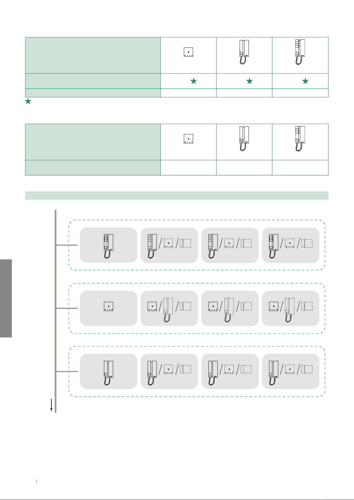
Maximum system expansion...................................................................4
Maximum expansion per apartment.......................................................4
Example of maximum expansion per apartment................................4
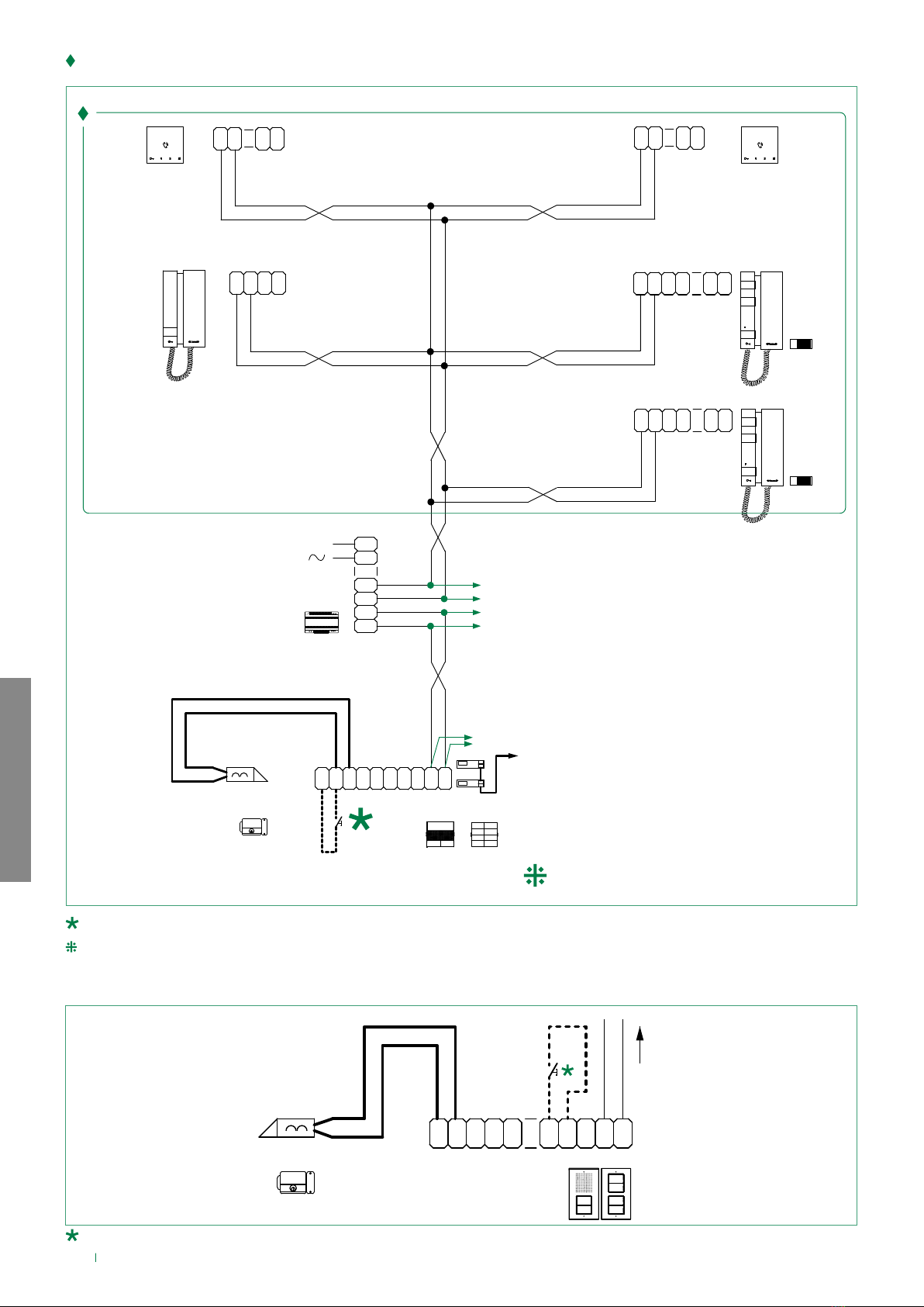
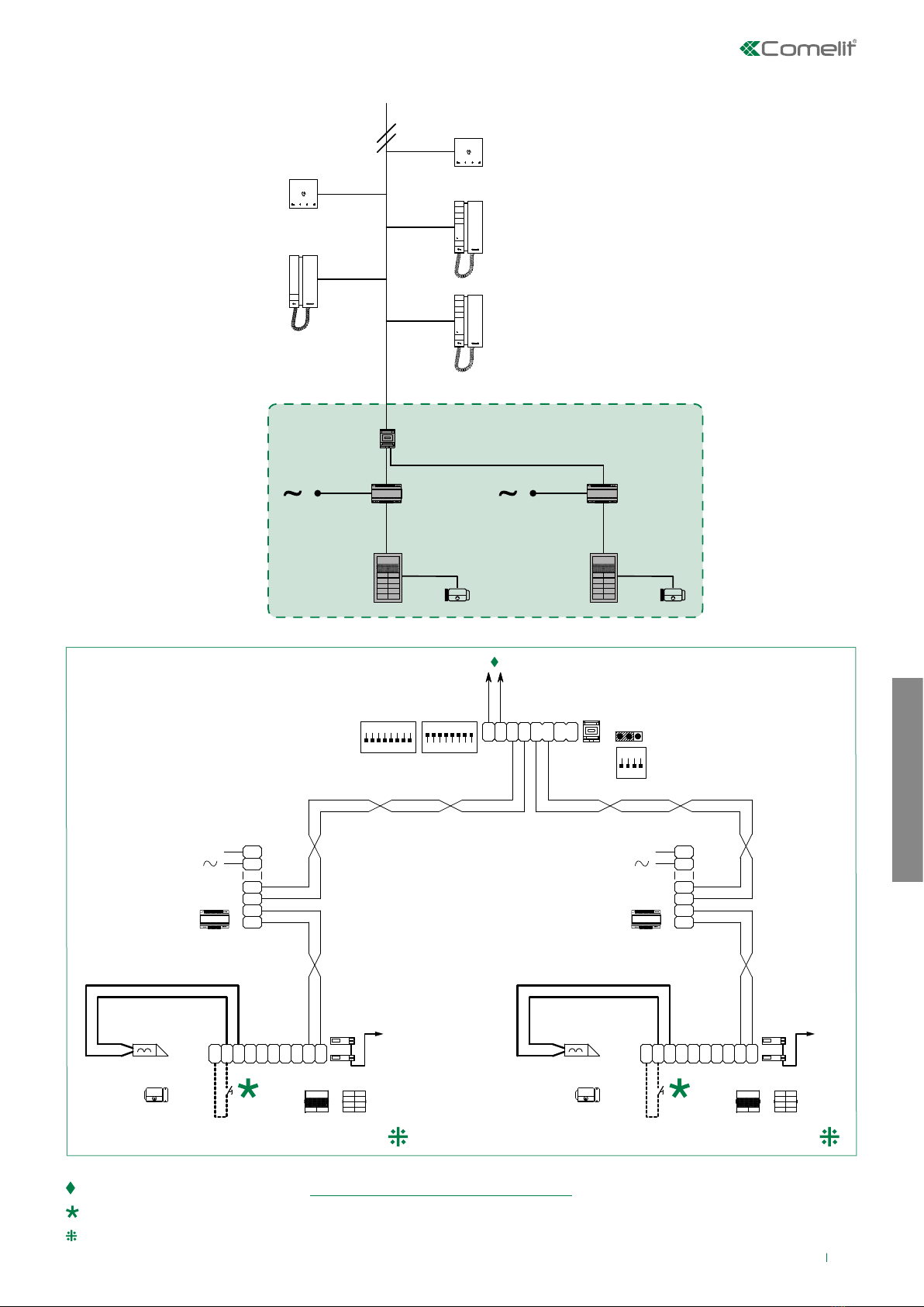
Wiring diagrams............................................................................... 5
Apartment block door-entry phone system ..........................................5
Variant with Ciao entrance panel............................................................6
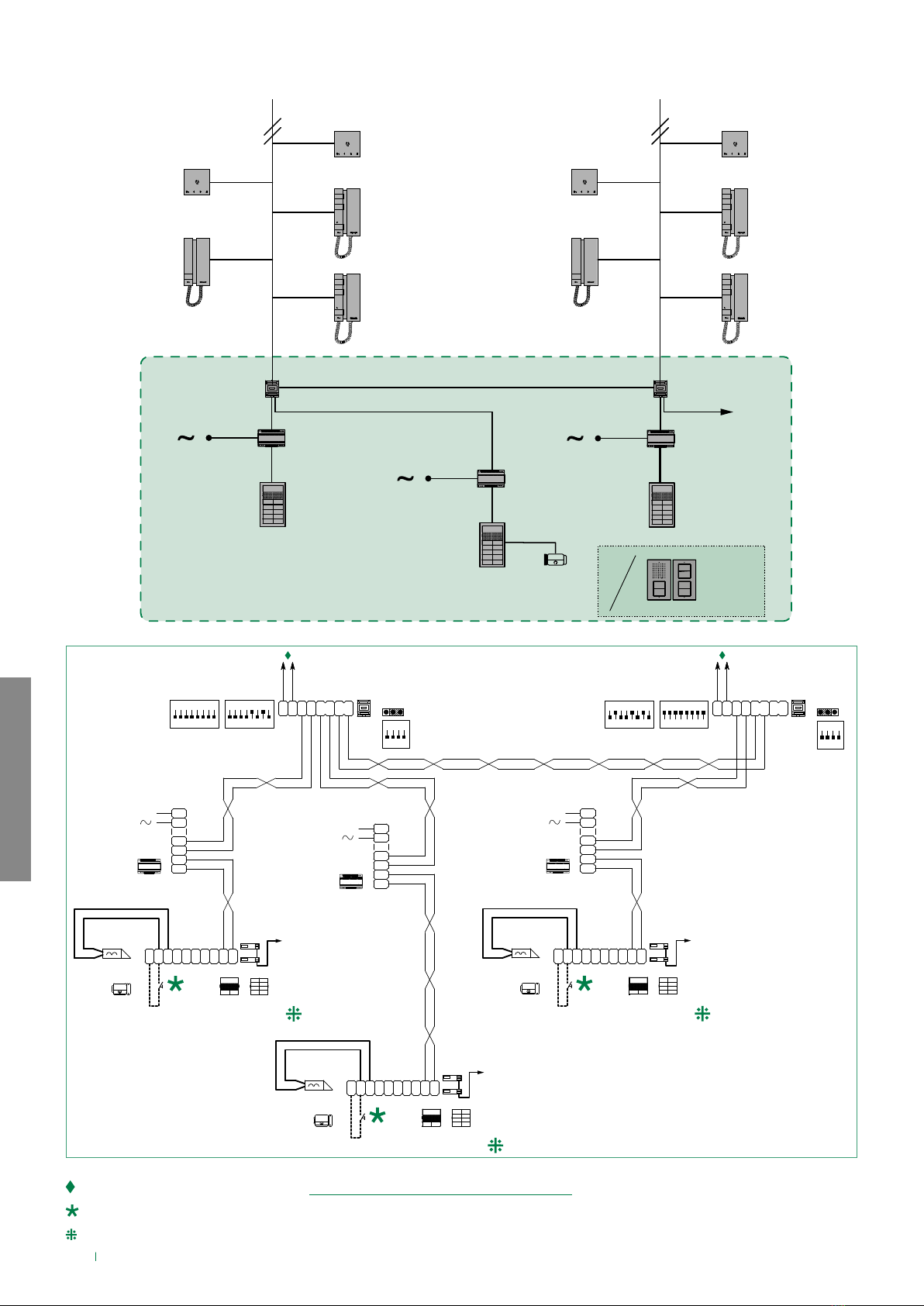
System with 2 main entrances................................................................7
System with 2 risers, one main entrance and n secondary entrances8
Table of contents
Warning
Intended use
This Comelit product has been designed and manufactured for use in the creation of audio and video communication
systems in residential, commercial, industrial and public buildings.
Installation
All activities connected to the installation of Comelit products must be carried out by qualified technical personnel, with
careful observation of the indications provided in the Manuals / Instruction sheets supplied with those products.
Wires
Disconnect the power supply before carrying out any operations on the wiring.
Use wires with a cross-section suited to the distances involved, observing the instructions provided in the system
manual.
We advise against running the system wires through the same duct as power cables (230V or higher).
Safe usage
To ensure Comelit products are used safely:
• carefully observe the indications provided in the Manuals / Instruction sheets,
• make sure the system created using Comelit products has not been tampered with / damaged.
Maintenance
Comelit products do not require maintenance aside from routine cleaning, which should be carried out in accordance
with the indications provided in the Manuals / Instruction sheets.
Any repairs must be carried out:
• for the products themselves, exclusively by Comelit Group S.p.A.,
• for the systems, by qualified technical personnel.
Disclaimer
Comelit Group S.p.A. does not assume any responsibility for
• any purpose other than the intended use,
• failure to observe the indications and warnings contained in this Manual / Instruction sheet.
Comelit Group S.p.A. reserves the right to change the information provided in this Manual / Instruction Sheet at any
time and without prior notice.

SIMPLEBUS2 AUDIO
3
System functions
B
A
A
C
6751W
2738W
2738W/A
2738W
2738W/A
1210A
UT2010
B
A
A
C
6751W
UT2010
1210A
2719W
SW2
S2
2719W
SW2
S2
CA2100P CA2100P
Operating distances
A MAX B MAX C MAX
Comelit Art. 4577/4579 1
mm² (Ø 1.2 mm AWG 17) 260 m
(850 feet)
130 m
(425 feet)
130 m
(425 feet)
UTP5 cat. 5 0.2 mm²
(Ø 0.5 mm AWG 24) 80 m
(260 feet)
40 m
(130 feet)
40 m
(130 feet)
0.28 mm²
(Ø 0.6 mm AWG 23) 100 m
(328 feet)
50 m
(164 feet)
50 m
(164 feet)
0.5 mm²
(Ø 0.8 mm AWG 20) 140 m
(460 feet)
70 m
(230 feet)
70 m
(230 feet)
1 mm²
(Ø 1.2 mm AWG 17) 200 m
(656 feet)
100 m
(328 feet)
100 m
(328 feet)
1.5 mm²
(Ø 1.4 mm AWG 15) 80 m
(260 feet)
40 m
(130 feet)
40 m
(130 feet)
UTP5 cat. 5 0.2 mm²
(Ø 0.5 mm AWG 24)
MULTI PAIR CABLE
GREEN
ORANGE
BLU
GREEN / WHITE
ORANGE / WHITE
BLU / WHITE
BROWN / WHITE
BROWN
260 m
(850 feet)
130 m
(425 feet)
130 m
(425 feet)
UTP cable with multi-cable connection: FOLLOW THE COLOURS SHOWN IN THE DIAGRAM!

SIMPLEBUS2 AUDIO
4
Maximum system expansion
Maximum expansion per apartment
Devices
6751W
2738W 2738W/A 2719W
Maximum number of door-entry phones that can
be powered from art. 1210A 100 100 100
Call repetition devices that can be used 1229A 1229A 1229A
With the Ciao entrance panel, the system can manage up to 72 users by connecting to MAX 100 door-entry phones for
every riser
Devices
6751W
2738W 2738W/A 2719W
Maximum number of internal units (including call
repetition devices) with the same user code 444
Example of maximum expansion per apartment
APARTMENT 2: max 4 internal units
APARTMENT 1: max 4 internal units
1210A
Art. 6751W
Art. 2738W / 2738W/A
APARTMENT 3: max 4 internal units Art. 2719W

SIMPLEBUS2 AUDIO
5
Wiring diagrams
Apartment block door-entry phone system
Apartment 2
Apartment 3
Apartment 4
Apartment 5
6751W
2719W
6751W
2738W
2738W/A
Apartment 1
2719W
UT2010
1210A
CA2100P
+ CA2200P

SIMPLEBUS2 AUDIO
6
1210A
L
N
230V
L2
L2
L1
L1
UT2010 UT9200
(MAX 8)
E
T
R
GND
SE-SE
+
NO NC
C
O
M
LL
+
VV
-
L L
C
F
P
C
F
P
2738W
2738W/A
4 4
PC
L L
C
F
P
C
F
P
2719W
4 4
PC
L L
C
F
P
C
F
P
2719W
6751W
C
F
P
LL
C
F
P
12
C
F
P
LL
C
F
P
12
6751W
34-35 Vdc
34-35 Vdc
32-34 Vdc
SW2
S2
SW2
S2
Max 20 m. Local door-opener button.
For configurations other than those indicated in the diagram, refer to the full manual for product number UT2010.
Max 20 m. Local door-opener button.
Variant with Ciao entrance panel
AUDIO DOOR-ENTRY SYSTEM RISER
LL
O
D
E
T
R
NO
SE
-
SE
+
NC C
M
O
C
CA2100P
+CA2200P
1210A

SIMPLEBUS2 AUDIO
7
System with 2 main entrances
2719W
6751W
6751W
2738W
2738W/A
2719W
1404
UT2010
1210A
UT2010
1210A
Audio door-entry system riser (see: “AUDIO DOOR-ENTRY SYSTEM RISER”)
Max 20 m. Local door-opener button.
For configurations other than those indicated in the diagram, refer to the full manual for product number UT2010
1404
L
M
L
M
L
S
L
S
LP
IN
LP
OUT
AB
JP1
ON
S1
MIN
1 2 3 4 6 75 8
ON
S2
MAX
1 2 3 4 6 75 8
ON
S3
1234
1210A
L
N
230V
L2
L2
L1
L1
1210A
L
N
230V
L2
L2
L1
L1
UT2010 UT9200
(MAX 8)
E
T
R
GND
SE-SE
+
NO NC
C
O
M
LL
+
VV
-
UT2010 UT9200
(MAX 8)
E
T
R
GND
SE-SE
+
NO NC
C
O
M
LL
+
VV
-

SIMPLEBUS2 AUDIO
8
System with 2 risers, one main entrance and n secondary entrances
1404
UT2010
1210A
1404
UT2010
1210A
UT2010
1210A
2719W
6751W
6751W
2738W
2738W/A
6751W
6751W
2738W
2738W/A
2719W
2719W
2719W
CA2100P
+ CA2200P
1404
L
M
L
M
L
S
L
S
LP
IN
LP
OUT
AB
JP1
1404
L
M
L
M
L
S
L
S
LP
IN
LP
OUT
AB
JP1
1210A
L
N
230V
L2
L2
L1
L1
UT2010 UT9200
(MAX 8)
E
T
R
GND
SE-SE
+
NO NC
C
O
M
LL
+
VV
-
1210A
L
N
230V
L2
L2
L1
L1
UT2010 UT9200
(MAX 8)
E
T
R
GND
SE-SE
+
NO NC
C
O
M
LL
+
VV
-
1210A
L
N
230V
L2
L2
L1
L1
UT2010 UT9200
(MAX 8)
E
T
R
GND
SE-SE
+
NO NC
C
O
M
LL
+
VV
-
ON
S1
MIN
1 2 3 4 6 75 8
ON
S2
MAX
1 2 3 4 6 75 8
ON
S3
1234
ON
S1
MIN
1 2 3 4 6 75 8
ON
S2
MAX
1 2 3 4 6 75 8
ON
S3
1234
Audio door-entry system riser (see: “AUDIO DOOR-ENTRY SYSTEM RISER”)
Max 20 m. Local door-opener button.
For configurations other than those indicated in the diagram, refer to the full manual for product number UT2010.

3rd edition 10/2020
code 2G41000018
www.comelitgroup.com
Via Don Arrigoni, 5 - 24020 Rovetta (BG) - Italy
CERTIFIED MANAGEMENT SYSTEMS
Other manuals for Simplebus2 Mini 2738W/A
3
Table of contents