Comfort Flex CLIWP Series User manual

Installation, Operation and
Maintenance Manual
IOM
Group: Wall Mounted Package
Part Number: CLIWP IOM
Date: 02 May 2023
CLIWP Series
Direct Expansion Unit with Scroll
Compressor
Model
3 RT / 5 RT
Refrigerant HFC-410A
60 Hz

iom-cliwp-eng
2
www.comfort-ex.com
©2023 Comfort Flex. Illustration and data cover the Comfort Flex product at the time of publication and we reserve the right to make
changes in design and construction at any time without notice.
Manufactured in an ISO 9001 certified facility

iom-cliwp-eng
3
www.comfort-ex.com
Pre-Startup Checklist - Direct Expansion Unit with Scroll Compressor
Must be completed, signed and delivered to Comfort Flex at least 2 weeks prior to the requested start date.
Job name
Place of installation
Customer order number
Model number(s)
G.O. Number(s)
Electrical Yes No N/A Initials
Building controls in operation
* Power cables connected to power block or optional disconnect switch
Power cables have been checked for proper phasing and voltage
All interlock scripts are complete and meet unit specifications
Power is applied at least 12 hours prior to start-up
Oil heaters energized at least 12 hours prior to startup
Cooler components (EXV sensor transducers) installed and wired properly
*Wiring complies with National Electrical Code and local codes (See NOTES)
Various Yes No N/A Initials
Unit control shuts down / disconnects
Factory overhaul of evaporator/condenser lines
Leak, evacuation and charge check of all refrigeration piping/components
Sensors, control, etc., installed
Minimum system load of 80% of available capacity to test/adjust controls
Attachment: Technical breakdown of selection software
Attachment: Acknowledgement of Final Order Receipt
NOTES: The most common problems that delay start-up and affect unit reliability are:
number and type of conductors and conduits installed:
__________________________________________________________________
Contractors' representative
Signature
Name
Company
Date
Phone / Mail
Comfort Flex Sales Representative
Signature
Name
Company
Date
Phone / Mail

iom-cliwp-eng
4
www.comfort-ex.com
This manual contains safety instructions that must be followed during installation and maintenance of the unit. Read this manual before
installing or operating this unit.
NOTE: Installation and maintenance should be performed only by qualified personnel who are familiar with local codes and regulations
and who have experience with this type of equipment.
! DANGER !
LOCK OUT/LABEL all power sources before starting, pressurizing, depressurizing or shutting down the equipment.
Disconnect electrical power before servicing equipment. More than one disconnection may be required to deenergize the unit.
Failure to follow this warning to the letter can result in serious injury or death. Be sure to read and understand the installation,
operating and service instructions in this manual.
! DANGER !
Danger indicates a dangerous situation which, if not avoided, will result in death or serious injury.
! WARNING !
Warning indicates a potentially dangerous situation which may result in property damage, personal injury or death if not avoided
!CAUTION !
Caution indicates a potentially dangerous situation which may result in minor injury or equipment damage if not avoided.
! WARNING !
Electric shock danger. Improper handling of this equipment can cause personal injury or equipment damage. This equipment must
be properly grounded. Control panel connections and maintenance should be performed only by personnel knowledgeable in the
operation of the equipment being controlled. Disconnect electrical power before servicing equipment. Be sure to install a earth
leakage circuit breaker. Failure to install a earth leakage breaker may result in electric shock or fire.
! WARNING !
If refrigerant leaks from the unit, there is a potential choking danger as the refrigerant will displace air in the immediate area. Be
sure to follow all applicable published industry-related standards and local, state, and federal statutes, regulations, and codes if
refrigerant is produced. Avoid exposing refrigerant to an open flame or other ignition source.
! WARNING !
Polyolester oil, commonly referred to as POE oil, is a synthetic oil used in many refrigeration systems and may be present in this
Comfort Flex product. POE oil, if it ever comes in contact with PCV/CPVC, will coat the inside wall of the PVC/CPVC pipe and
cause environmental stress fractures. Although there is no PCV/CPCV pipe in this product, keep this in mind when selecting
piping materials for your application, as system failure and property damage could occur. Consult the pipe manufacturer’s
recommendations to determine appropriate pipe applications.
! CAUTION !
Static sensitive components. Static discharge during handling of the electronic circuit board can cause damage to components.
Use a static strap before performing any service work. Never unplug any cables, circuit board terminal blocks, or power plugs while
power is applied to the panel.
!CAUTION !
When moving refrigerant to/from the cooler using an auxiliary tank, a grounding strap should be used. An electrical charge builds
up when halo-carbon refrigerant travels in a rubber hose. A grounding strap should be used between the auxiliary refrigerant tank
and the cooler end sheet (ground to ground), which will safely carry the charge to ground. Failure to follow this procedure may result
in damage to sensitive electronic components.
DANGER IDENTIFICATION INFORMATION
NOTES: Indicate important details or clarifying statements for the information presented.

iom-cliwp-eng
5
www.comfort-ex.com
Comfort Flex’s CLIWP series direct expansion wall attached
package cooling systems are complete, self-contained, automatic
equipment designed for outdoor installation. The package units
are fully assembled, factory wired, charged and tested.
The electrical control center includes all operating controls and
equipment protection necessary for reliable automatic operation.
Components housed in a weatherproof control panel.
NOMENCLATURE
CLIWP-036-U-F-L-C-T-C-A-P-1-N-C- D-M-1-4-0
FAMILY
CAPACITY (BTU)
036 - 36,000 Btu/H
060 - 60,000 Btu/H
DISCHARGE AIR
U - Upper
COMPRESSOR
F - Fixed
COMPRESSOR SIDE
L - Left
R - Right
VOLTAGE
C- 208 - 230 / 3 / 60
D- 460 / 3 / 60
P- 220 / 1 / 60
CONTROL
T - Thermostat
P - Parametric
L - Loytec
EVAPORATOR FAN
C - AC fixed
CONDENSER FAN
A - Axial standard
EXTRAS
0 - No
1- 5 Kw
2 -10 Kw
REFRIGERANT
4 - R410-A
FOOT PRINT
1 - Large (3 & 5 Tons)
2 - Small (3 Tons)
CONDENSER
M - Al-Al Microchannel
C - Al -Cu
PACKAGING
D - Domestic
I - International
C - Bottom Crate
OPERATION
C - Cooling Only
EXTERNAL AIR
N - N/A
E- Economizer
GRILLS
1 - Single deflection
ANTICORROSION
P - Paint
E- Evaporator
C - Condenser
D - Evaporator & Condenser

iom-cliwp-eng
6
www.comfort-ex.com
EFFICIENCY
CLIWP units are designed to meet the needs of any project
for telecommunications networks, data centers, laboratories,
schools, hospitals and industrial use.
CLIWP units have diverse applications and can be installed
individually or in any combination to achieve the exact capacity of
the project. Their high efficiency and easy operation achieves the
desired temperatures accurately, quickly and with efficient energy
consumption.
The CLIWP units can work 1 + 1 (by means of a separately
purchased sequencer), i.e., one in operation and one in backup.
The units have different connectivity and remote monitoring
options using the most common protocols such as ModBus,
BACnet and TCP/IP.
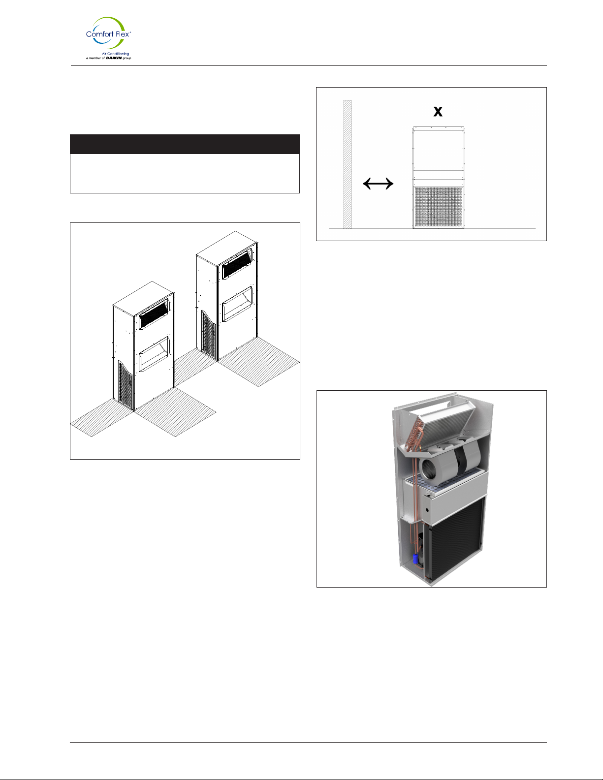
SELF CONTAINED AND SELF SPACE
SAVING
The CLIWP unit is completely self-contained. All its components
are inside the cabinet. It uses no usable space in the room to
be conditioned, it is installed on an exterior wall with a minimum
volume, without requiring roof areas or exterior floors.
EASY TO INSTALL
The equipment is assembled, wired, charged with refrigerant, oil
and is systematically factory tested to ensure that you will have a
quick and trouble-free installation.
DESIGN
The work carried out by our engineering and development
department has resulted in equipment with high efficiency in
design and optimum performance during operation.
The selection of high quality main components, our quality
processes and the control system during manufacturing,
guarantee a high performance and safety equipment.
All major components are rigorously tested and validated before
installation. Each engineered unit has undergone long hours of
rigorous testing to ensure the efficiency, safety, durability and
quality of the entire system.
All external paint is baked-on and meets the most stringent quality
standards (ASTM-B117 1500 hour salt spray test).
The selection of high-end compressors and heat exchangers
ensures the capacity and high efficiency of the equipment.
All our equipment has a reduced footprint, which facilitates
installation and maintenance maneuvers, being able to make use
of stairs, doors and service elevators to move the equipment.
COMMUNICATION
Our equipment can be connected / integrated through different
communication protocols; such as TCP/IP, ModBUS and BacNet**,
the most common protocols used in the Air Conditioning industry.
Our equipment keeps track of all programmable variables in
real time, such as system load monitoring, specific alarms of the
refrigeration cycle, and the electrical system.
MAINTENANCE
The simplicity in the design of the equipment allows for maximum
ease of preventive/corrective maintenance. All major components
are available to maintenance personnel by simply opening the
service panels.
If an emergency shutdown occurs, the digital control of the
equipment will indicate in detail the cause of the alarm, helping to
facilitate and accelerate the solution of the alarm.
TESTS
NOTE:
The control system ensures the correct operation of the equipment
by monitoring in real time the condition of the major components
(high or low refrigerant pressure, compressor conditions and
electrical power monitoring).
In case of failure, the event will be recorded for later analysis,
facilitating the location of a possible failure and its solution.
* Depends on the type of control.
** The available communication protocols depend on the type of
control.
This equipment is charged with the refrigerant necessary for
proper
The units are tested at full load operation, thermal load and line
voltage at actual operating conditions.

iom-cliwp-eng
7
www.comfort-ex.com
PROPERTY TEST METHOD PERFORMANCE
Dry layer thickness ASTM D7091 0.6-1.2 mils / 15-30 µm
Brightness - 60 degrees ASTM D523 55-75
Pencil hardness ASTM D3363 2H minimum
Inmersion water ASTM D870 1000 hours
Cross hatch adhesion ASTM D3359 5B
Direct impact ASTM D2794 160 in-lb
Salt spray corrosion ASTM B117 / DIN 53167 More of 15,000 hours
Humidity ASTM D2247 1000 minimum hours
Reduction of heat transfer -- Less than 1%
Improved flap coating -- Up to 30 flaps per inch
pH range -- 3-12
Temperature limits -- -40°F to 325°F / -40°C to 163°C
(Dry load)
TECHNICAL FEATURES
ElectroFin® E-Coat Coil coating corrosion
resistant factory-applied
ElectroFin® E-Coat is a flexible, water-based, cationic epoxy
polymer using an electrodeposition coating process designed
specifically for heat transfer coils in heating, air conditioning and
refrigeration systems. The PPG POWERCRON® HE (high edge)
technology enhances fin edge coverage through a polymerized
through a unique polymer that controls the flow characteristics
of the coating.
Electrofin® E-Coat Meets The Following Testing Standards
• ASTM B117 / DIN 53167 Salt spray test - over
over 15,000 hours.
• ASTM G85 Annex A3 SWAAT Salt Spray Test
with modified salt - 3000 hours.
• Division 23 specification for main construction
VA for High Humidity Installations.
• CID AA-52474A (GSA)

iom-cliwp-eng
8
www.comfort-ex.com
When transporting the unit, the use of a forklift or crane is
recommended. All units are provided with lifting points. Only
these points should be used for lifting the unit as shown in Fig. 1.
INSPECTION
HANDLING
The equipment must be checked once it has arrived at its
installation site for any damage. All components described in the
delivery NOTE must be inspected and checked. In the event that
there is evidence of damage, do not remove or repair the damaged
components and immediately report the severity and type of
damage to the carrier and your sales representative if possible
send photographs that may help explain/detail the damage.
NOTE: Any damage detected during transport must be
reported and documented to the manufacturer prior
Before installing the equipment, check that the model and voltage
shown on the nameplate are correct. The manufacturer will not
be responsible for any damage once the equipment is accepted.
The correct space dedicated for the maintenance of the equipment
will allow a better installation and maintenance, facilitating the
access to the service points for the technical personnel. Refer
to the schematics presented for unit dimensions. At least one (1)
meter is required to service the compressor, allow sufficient space
for opening control panel doors. Refer to Figure 3 for minimum
clearances. In all cases, these precedents are established for any
need for compliance with local regulations.
! DANGER !
Improper rigging, lifting or moving of a unit can result
in property damage, serious personal injury or death.
Follow the rigging and moving instructions carefully. Do
not stand under the unit while it is being lifted or installed.
NAMEPL ATES
The unit nameplate is located on the outside of the unit power
panel. Both the model number and serial number are located on
the unit nameplates; the serial number is unique to the unit.
These numbers should be used to identify the unit in case of
service, parts or warranty questions. This nameplate also contains
the unit’s refrigerant charge and electrical ratings. The evaporator
nameplate is under the insulation and contains the serial number.
The compressor nameplate is located on each compressor and
provides pertinent electrical information.
! WARNING !
Installation should be performed by qualified personnel who
are familiar with local codes and regulations.
! CAUTION !
All lifting locations must be used to avoid damage to the unit.
Figure 1. Required elevation arrangement.
Maximum standby ambient temperature 120° F (48.8°C)
Maximum operating ambient temperature 110°F (43.3°C)
Minimum operating ambient temperature (standard) 64°F (18°C)
Cold air outlet temperature (At AHRI conditions Return 80°F, 67°F, Ambient 95°F, 68°F) Oulet 60°F (15.5°C)
Maximum evaporator inlet fluid temperature 85°F (29.4°F)

iom-cliwp-eng
9
www.comfort-ex.com
MOUNTING
Installation should be done in the order shown below:
UNIT PLACEMENT
The equipment must be installed in accordance with national
and local safety standards. If no local standards are applicable,
the installation must be carried out in accordance with national
standards.
Figure 2. Distance for preparation and assembly.
1. Verify that the mounting wall has the capacity to support the
weight of the equipment. If not, consult a specialist to place an
additional base (not included in the equipment).
The unit is installed against the wall, with passages through the
wall on the outside of the space to be conditioned.
Injection and return wall openings should exceed 1/2” on each
side of the unit openings so that the grille can be installed.
It must be ensured that it is well leveled and thus ensure the
proper flow of refrigerant gas and compressor oil, as well as an
effective condensate drain.
2. Using a spirit level, mark the outside wall with a level horizon-
tal line at the height where the base of the equipment will rest,
this at 0.973m above the bottom level of the booth.
3. Prepare the injection and return openings in the outer wall by
measuring from the line just marked. The equipment comes
with a preparation available for different airflow passages.
4. Prepare the mounting holes, these can be pilot holes with 3/8”
or 10mm drill bit for the screws to be placed in the unit and
secured with nuts from the inside or screws mounted on the
base to place the unit and place the nuts on the outside.
5. Secure the base mounting angle of the unit to the exterior
wall with four 5/16” 1” long self-tapping screws or 8 mm and
25 mm long self-tapping screws (not included) at 21 mm be-
low the marked line and center with the openings. Each hole
spaced 296 mm apart.
6. Cold silicone seal the perimeter of the unit to prevent infiltra-
tion of rainwater into the site.
7. Then reload the unit onto the base angle making sure that the
screw holes are aligned.
8. Remove the mounting bracket.
Evaporator Cover
Control Panel
Compressor/
Fan Grille
Side Cover
Side Grille
Return grille
mounting pass
Injection grille
mounting pass
1 1/2¨ bracket profile
for temporary support
(Drill 11.5¨ holes on
cabin with self-tapping
screws)

iom-cliwp-eng
10
www.comfort-ex.com
Decorative walls are often used to help conceal a unit, either on
the ground or on the roof. Whenever possible, design these walls
so that the combination of their open area and distance to the unit
does not affect performance.
PIPE CONNECTION
The CLIWP is a self-contained, packaged unit, meaning that all
refrigerant piping connections are made at the factory, so the only
connection required to be made will be from the equipment drain
to the on-site plumbing drain (not included in the kit).
Figure 4. Building or wall on one side of the unit.
NOTE: Welded pipe connections between the filter and
Figure 5. Factory installed strainer
The space must be perfectly insulated to avoid infiltration and air
leakage on site. The door must seal properly at closing.
Site Considerations:
The CLIWP equipment should be mounted on a wall on the outside
of the room to be conditioned, either prior to final placement or
while the booth is already installed.
It is also imperative to consider a free area for air intake, condenser
discharge and equipment maintenance. To ensure air intake, the
unit should be mounted in a clean location, away from loose soil
and external materials that may congest the condenser.
It should not be mounted near steam vents, hot air or chimneys.
It is recommended that the unit be mounted at a distance greater
than 2.00m from any wall, other equipment or obstruction to the
passage of air (Figure 4).
CLEANING SERVICE
The control panels are located on the front of the unit and require
a minimum clearance of 1 meter. The compressor, filter-driers and
line shutoff valves are accessible on each side or end of the unit.
! WARNING !
Do not block access to the sides or ends of the unit with piping
or ductwork.
These areas must be open for service access.
1000 mm²
1000 mm
1000 mm²
1000 mm
1000 mm
1000 mm
Figure 3. Cleaning service.

iom-cliwp-eng
11
www.comfort-ex.com
INJECTION AND RETURN AIR SUPPLY
These Air Conditioning units are designed to adequately distribute the air flow for telecommunications, data centers, laboratories,
schools, hospitals, industrial use, etc. In addition to having a pressure drop calculated to operate only with the injection and return grilles,
so no additional duct connection is required.
! DANGER !
Risk due to weight of the unit (+/-235 kg depending on the model) can cause serious injury. Take precautions. The use of safety
equipment is not optional when handling this equipment.
CONDENSER COIL COATING AND OPTIONS
Considerations
Coil Option Unpolluted
marine² Industrial³
Standard
Microchannel +++ - - -
Modine
Coated coils +++ +++ +++ ++
NOTES:
1.
2.
3.
4.
The standard CLIWP unit coils have an aluminum alloy microchannel design with a series of flat tubes containing multiple parallel flow
microchannels placed between the refrigerant collectors.
ElectroFin® E-Coat is a flexible, water-based, cationic epoxy polymer using an electrodeposition coating process designed specifically
for heat transfer coils in heating, air conditioning and refrigeration systems. The PPG POWERCRON® HE (high edge) technology
enhances fin edge coverage through a polymerized through a unique polymer that controls the flow characteristics of the coating.
The heat exchanger coil (HX) shall have a flexible cationic epoxy e-coat applied uniformly on all metal surfaces with no material
bridging between the fins. The electrodeposition coating will ensure complete HX encapsulation of all conductive surfaces with a
uniform thickness of 0.6 to 1.6 to 1.0 fof 0.6 to 1.2 mil (15 to 30 μm). The e-coat coating meets ASTM B3359 classification 5B for cross-
hatch adhesión according to ASTM B3359. Corrosion durability is confirmed by tests of not less than 15,000 by testing for not less than
15,000 hours of salt spray resistance per ASTM B3359. ASTM B117 using traced aluminum as test coupons. After curing of the e-coat ,
HX will receive a spray-applied 2K polyurethane black topcoat to prevent to prevent UV degradation of the e-coat epoxy film. The topcoat
will have a gloss of 60 (>90%) and a dry film thickness of 50 to 60 μm.
SPECIFICATION FOR COIL COATING

iom-cliwp-eng
12
www.comfort-ex.com
Figure 6. CLIWP refrigeration schemes.

iom-cliwp-eng
13
www.comfort-ex.com
Figure 7. CLIWP cooling only 3 RT (This dwg is for small
footprint and only available for 3 RT)
Right side view
Isometric view
Front view
Top view
Back view
OUT
IN
246.6 mm
[911 16 in]
760.0 mm
[2915 16 in]
404.0 mm
[1578in]
1761.4 mm
[6938in]
Total height
1087.8 mm
[4213 16 in]
Total width
317.7 mm
[1212in]
299.8 mm
[1113 16 in]
317.7 mm
[1212in]
48.2 mm
[178in]
103.0 mm
[4116 in]
318.0 mm
[1212in]
75.0 mm
[215 16 in]
317.7 mm
[1212in]
317.6 mm
[1212in]
612.3 mm
[2418in]
Total length
1042.2 mm
[41116 in]
581.9 mm
[2215 16 in]
Electrical
control
Condenser
Maintenance
access
Electrical
control
n
12.7mm
[
n
12
in]
Electrical
control
Evaporator
Air return
760.0 mm
[2915 16 in]
Air supply

iom-cliwp-eng
14
www.comfort-ex.com
Figure 8. CLIWP Cooling Only 3 & 5 RT Standard Size.
Left side view
Isometric viewFront view
Top view
Back view
613.3 mm
[24
18
in]
Total length
2109.7 mm
[83
116
in]
Total height
318.0 mm
[12
12
in]
318.0 mm
[12
12
in]
317.7 mm
[12
12
in]
317.7 mm
[12
12
in]
317.6 mm
[12
12
in]
317.7 mm
[12
12
in]
75.0 mm
[2
15 16
in]
103.1 mm
[4
116
in]
48.2 mm
[1
78
in]
317.7 mm
[12
12
in]
299.8 mm
[11
13 16
in]
317.7 mm
[12
12
in]
1087.9 mm
[42
13 16
in]
Total width
Electrical
panel
Air supply
Air return
n
12.7mm
[
n
12
in]
x18
583.0 mm
[22
15 16
in]
1040.0 mm
[40
15 16
in]
Condenser
Evaporator
OUT
IN
299.2 mm
[11
34
in]
404.0 mm
[15
78
in]
760.0 mm
[29
15 16
in]
760.0 mm
[29
15 16
in]
1061.1 mm
[41
34
in]
70.7 mm
[2
13 16
in]
Maintenance
access

iom-cliwp-eng
15
www.comfort-ex.com
Any system that has been exposed to the atmosphere must be
properly dehydrated. This is achieved with a proper vacuum
procedure.
To achieve a proper vacuum, a VACUUM PUMP (not a
compressor) and a VACUOMETER are required.
The procedure is as follows:
• First of all, the access points to the system must be defined.
For both the low and high side, use the existing service
valves on the condensing unit, i.e. the high pressure switch,
connected to the smaller diameter pipe, and the low pressure
switch, connected to the larger diameter pipe.
• Once this is done, the system can be drained.
Basically, it can be done in two ways:
• DILUTION METHOD
1. Turn on the vacuum pump and build up vacuum in the pump
(register 1 closed).
2. Open register 1 and let the system evacuate until at least
500 microns are reached. To obtain the measurement, close
register 1 and open register 2 and make the vacuum gauge
feel the system pressure. After reaching 500 microns, isolate
the vacuum pump and open register 3, letting the Nitrogen
pass through to break the vacuum. Isolate the Nitrogen tube.
3. Vent the Nitrogen through the connection between the copper
line and register 3.
4. Repeat the operation at least twice, making the third evacua-
tion in the last phase. At the end at least 200 microns should
be obtained.
! WARNING !
Never disconnect the copper tube from register 3, simply
loosen the connection to expurgate the nitrogen.
To obtain an accurate vacuum value, isolate the vacuum pump
from the system by closing register 1 and waiting about 5 minutes
for an accurate measurement. If the value does not hold, the
system still has moisture or there is a leak. Always check all
connections (points 1, 3 and valves).
• HIGH VACUUM METHOD
1. It is applied with a vacuum pump capable of achieving a vac-
uum of less than 200 microns in a single evacuation. Proceed
as follows:
2. Turn on the vacuum pump and then open the register 1. Sub-
sequently, isolate the vacuum pump and open the register 2
(Fig. 10).
3. When a value of less than 200 microns is obtained (try to
reach the lowest possible value), the vacuum procedure is
finished.
! WARNING !
The pump oil should be changed periodically to ensure
vacuum efficiency.
REFRIGERANT CHARGEVACUUM PROCESS
After evacuating the system properly, close the manifold registers
and isolate the vacuum pump, vacuum gauge and nitrogen tube.
To make the refrigerant gas charge, replace the Nitrogen tube
(Figure 10) with a refrigerant gas tube. Purge the hose connecting
the tube to the service valve.
Open the service valve that provides access to the refrigerant gas
tube and then the manifold discharge port.
To properly charge the system, check the unit identification labels
for the amount of refrigerant gas to be added to the system.
With the system stopped, charge the liquid refrigerant gas through
the liquid line service valve (smaller diameter). To assist you, use
a scale (if a graduated tube is not used). Wait at least 10 minutes
before turning on the equipment.
Close the manifold discharge register, open the suction register
and with the system running complete the charge with refrigerant
gas in gas form (5% to 20% of the total). Check on the scale
the weight of the refrigerant gas that was added to the system.
If the charge is complete, close the manifold suction register,
disconnect the suction and discharge hoses and close the pipe
register.
The loading procedure is completed.
If for any reason there is a need to remove/lose refrigerant gas,
the service valves on these units allow the refrigerant gas to be
collected from the system inside the condensing unit.
Procedure:
1. Connect the manifold hoses to the service valve ports on the
condensing unit.
2. Close the 1/4” liquid line service valve.
3. Turn the unit on cool down observing that the system pres-
sures reach 2 psi.
At this time close the 3/8” suction line service valve to allow the
refrigerant gas to be collected.
REFRIGERANT GAS RECOVERY
NOTE:
You can check the charge
Figure 9. Service valves

iom-cliwp-eng
16
www.comfort-ex.com
Figure 10. Diagram to vacuum and refrigerant charge.
Table 1. Refrigerant charge.
FAMILY RT
TXV EXV
R410A (KG) R410A (KG)
CLIWP 3 6 - -
CLIWP 5 - -
NOTE:

iom-cliwp-eng
17
www.comfort-ex.com
! CAUTION !
Static discharge during handling of the circuit boards can
cause damage to the components. Use an antistatic strap
before performing any maintenance work. Never unplug
cables, circuit board terminal blocks or plugs while the panel
is powered.
USE WITH ON-SITE GENERATORS
Switching from site mains to generator power and vice versa
requires the equipment to be off or the power to be disconnected
for more than five seconds to avoid sending out-of-phase voltage
to the same.
A properly installed and fully synchronized automatic transfer
switch must be used to transfer power if the equipment is
operating under load.
Generator sizing
! WARNING !
The generator should be sized by an electrical engineer
familiar with generator applications.
Proper transfer of power from the standby generator to the grid is
essential to prevent damage to the equipment and must be used
to ensure proper operation of the unit.
! WARNING !
Stop the unit before transferring power from the generator
to the mains.
Transferring power while the equipment is running can
cause serious damage to the same.
The procedure required to reconnect generator power to the grid
is as follows:
1. Set the generator to always run five minutes longer than the
unit start timer, which can be set from two to sixty minutes,
while keeping the equipment powered by the generator until
the fully synchronized Automatic Transfer Switch properly de-
livers the equipment power from the site.
2. Set the transfer switch supplied with the generator to auto-
matically shut down the equipment before the transfer is
made. The automatic shutdown function can be accom-
plished through a BAS interface or with the “remote on/off”
wiring connection shown in the field wiring diagrams.
A start signal can be given at any time after the stop signal, as the
three-minute start timer will be in effect.
Electrical wiring connections to the unit may be made with either
copper or aluminum wiring, provided the size and number of wires
match the equipment terminals.
All wiring must be in accordance with applicable local and national
codes, including NECA/AA 10402012 for installation of aluminum
wiring in buildings (ANSI). Refer to the unit nameplate and unit
selection report (technical data sheet) for correct electrical
ratings.
1. The control transformer is supplied and no separate 115V
power is required. For single and multipoint power connec-
tions, the control transformer is on circuit #1 with control pow-
er wired from there to circuit #2. For multipoint power, discon-
necting power from circuit #1 disconnects the control power
from the unit.
2. The size of the wiring supplied to the control panel should be
in accordance with the field wiring diagram. (See diagrams
from page 17).
3. The single point power supply requires a single disconnect
to supply electrical power to the unit. This power supply must
have a fuse or use a circuit breaker. (Fuse value depends on
unit model).
4. All field wiring terminal range values listed in the unit selection
report apply to 75°C cable per NEC.
5. It must be grounded per national and local electrical codes.
! DANGER !
Qualified and licensed electricians must perform wiring.
There is an electrical shock hazard that can cause serious
injury or death.
ELECTRICAL CONNECTION
CLIWP units have individual power connections per unit. The
wiring inside the unit is dimensioned in accordance with the
NEC®.
The required field wiring varies depending on the configuration
of the unit.
Voltage limitations are:
1. Within 10 percent of nameplate rating.
2. Voltage unbalance should not exceed 2%. Since a voltage
unbalance of 2% can cause a current unbalance of 6 to 10
times the voltage unbalance per NEMA MG-1, it is important
that phase-to-phase unbalance be kept to a minimum.

iom-cliwp-eng
18
www.comfort-ex.com
Figure 11. Typical field wiring diagram of cooling only unit
3RT 220V
! WARNING !
When installing the earth leakage protector make sure that it is compatible with the inverter (resistant to high frequency electrical
noise) to avoid unnecessary opening of the earth leakage protector.
3
AMP
22X
NC
31X
NC
14X
NO
43X
NO
CAL4-11
CAL4-11
21X
NC
32X
NC
13X
NO
44X
NO
COEL

iom-cliwp-eng
19
www.comfort-ex.com
MC1-T1
MC1-T2
MC1-T3
MC2-L2
MC2-L1
MC1-L1
MC1-L2
MC1-L3
T2-75-L1
T2-75-L3
R-2
T2-75-L3
MS-L3
MS-L2
MS-L1
C1-5L3
MC1-L3
MC1-L2
MC1-L1
1 x 8
1 x 3
6x PZ2/5.5
3.5 - 5 Nm
2 - 3 Nm
2 - 3 Nm
15 mm
11 mm
11 mm
In: 115A
Ui: 1000V
Ui: 1000V AC
1500V DC
ith: 125A
IEC 60947-7-1
1 x 8
1 x 3
6x PZ2/5.5
3.5 - 5 Nm
2 - 3 Nm
2 - 3 Nm
15 mm
11 mm
11 mm
In: 115A
Ui: 1000V
Ui: 1000V AC
1500V DC
ith: 125A
IEC 60947-7-1
1 x 8
1 x 3
6x PZ2/5.5
3.5 - 5 Nm
2 - 3 Nm
2 - 3 Nm
15 mm
11 mm
11 mm
In: 115A
Ui: 1000V
Ui: 1000V AC
1500V DC
ith: 125A
IEC 60947-7-1
CENTRIFUGAL FAN
AXIAL FAN
PHASE DETECTOR
COEL
MC2-T1
MC2-T3
Start
Connection
22X
NC
31X
NC
14X
NO
43X
NO
CAL4-11
CAL4-11
21X
NC
32X
NC
13X
NO
44X
NO
MC2-L3
R-2
FU2-1
FU3-1
3
AMP
3
AMP
R-1
R-2
3
AMP
3
AMP
T1-L2
T1-L1

iom-cliwp-eng
20
www.comfort-ex.com
Figure 12. Typical field wiring diagram of cooling only unit
3RT 440V
3
AMP
22X
NC
31X
NC
14X
NO
43X
NO
CAL4-11
CAL4-11
21X
NC
32X
NC
13X
NO
44X
NO
COEL
Table of contents
Popular Air Compressor manuals by other brands

Husky
Husky C271H Use and care guide

Profi-Partner
Profi-Partner 50222 manual

BLACKMER
BLACKMER NGH1013 Installation, operation and maintenance instructions

MY PROJECT
MY PROJECT MPKT 60 B2 Operation and safety notes translation of the original instructions

Sullivan-Palatek
Sullivan-Palatek D110PKU user manual

DeWalt
DeWalt D55270 instruction manual

Sealey
Sealey SAC2420A manual

Craftsman
Craftsman evolv 921.167500 Operator's manual

Zgonc
Zgonc YELLOW PROFILINE YPL 183-2 KIT Translation from the original instruction manual

PFT
PFT LK 402 III Instruction and maintenance manual

Powermate
Powermate 200-2645 Operator's & parts manual

Stealth
Stealth SAQ-12018 manual