Stratus SRC25 Manual

1
Installation and Service Manual
for SRC25, SRC252, SRC50, SRC502, SRC75, SRC752
Thank you for purchasing the Stratus SRC series rocking piston compressor. This instruc-
tion manual explains the product operations and gives important precautions regarding
its safe use. Please read and follow these instructions to experience years of trouble free
service on these top of the line units.
To avoid accident, do not use the compressor in any way other than as described in this
instruction manual especially when you see “WARNING”. After reading this instruction
manual, keep it nearby as a reference in case questions arise during use.
If this instruction manual should become lost or damaged, they are available on our
website www.easypropondproducts.com.
PRODUCT USE CRITERIA AND PURPOSE
• Pumponlyclean,dryair
• Protectunitfromdirtandmoisture
• Donotpumpflammableorexplosivegasesoruseinanatmospherethatcontains
such gases
• Protectallsurroundingitemsfromexhaustair,thisexhaustaircanbecomeveryhot
• Corrosivegasesandparticulatematerialwilldamageunit—watervapor,oil-based
contaminantsorotherliquidsmustbefilteredout
• Productperformancechangeswhenusingathighaltitudes
• Thispumpisoil-lessandrequiresNOlubrication
SAFETY:
Your safety and the safety of others is extremely important. We have provided many
important safety messages in this manual and on your compressor. Always read and
obey all safety messages.
This is the safety alert symbol. This symbol alerts you to hazards that can kill or
hurtyouandothers.Thesafetyalertsymbolandthewords“Danger”and“Warn-
ing” will precede all safety messages. These words mean:
Danger - You will be killed or seriously injured if you don’t follow instructions.
Warning - You can be killed or seriously injured if you don’t follow instructions.
All safety messages will identify the hazard, tell you how to reduce the chance of
injury and tell you what can happen if the safety instructions are not followed.
Rocking Piston Compressors
Please read this manual completely before installing and using this compressor.
Save for future reference and keep in the vicinity of the compressor.

2
INSTALLATION:
WARNING!ElectricalShockHazard.Disconnectelectricalpoweratthe
circuit breaker or fuse box before installing this product. Install this product
where it will not come into contact with water or other liquids. Install this product where it
will be weather protected. Electrically ground this product. Failure to follow these instruc-
tionscanresultindeath,fireorelectricalshock.
Correct installation is the responsibility of installer. Make sure of proper installation condi-
tionsandthatclearancesdonotblockairflow.
WARNING! Blockingairflowovertheproductinanywaycancauseproductto
overheat.
MOUNTING:
Compressor may be installed in any orientation. Mounting the product to a stable, rigid
operating surface and using shock mounts will reduce noise and vibration.
PLUMBING:
RemoveplugsfromtheINandOUTports.Connectwithpipeandfittingsthatarethe
same size or larger than threaded ports. Be sure to connect the intake and exhaust
plumbing to the correct inlet and outlet ports. Ports will not support plumbing.
ACCESSORIES:
Thecompressor’sexternalintakewillprovideadequatefiltrationinmostapplications.
Checkfiltersperiodicallyandreplacewhennecessary.Installreliefvalvesandgaugesat
inlet, outlet or both, to monitor performance. Check valves may be required to prevent
backflowthroughpump.
MOTOR CONTROL:
It is your responsibility to contact a qualied electrician and assure that the electri-
cal installation is adequate and in conformance with all national and local codes/
ordinances. The metal capacitor must be grounded.
The wiring diagram supplied with the compressor provides required electrical information.
Check that power source is correct to properly operate the dual-voltage motors.
ELECTRICAL:
WARNING! Electrical Shock Hazard. This product must be properly
grounded.Donotmodifytheplugprovided.Ifitwillnotfittheoutlet,have
theproperoutletinstalledbyaqualifiedelectrician.Ifrepairorreplacementofthecordor
plugisnecessary,donotconnectthegroundingwiretoeitherflatbladeterminal.Check
theconditionofthepowersupplywiring.Donotpermanentlyconnectthisproductto
wiring that is not in good condition or is inadequate for the requirements of this product.
Failuretofollowtheseinstructionscanresultindeath,fireorelectricalshock.
Model with a power supply cord: This product must
be grounded. For either 120 volt or 220/240 volt circuits
connect power supply cord grounding plug to a matching
groundedoutlet.Donotuseadapter.Seediagramatright.
In the event of an electrical short circuit, grounding re-
duces the risk of electric shock by providing an escape
wire for the electric current. This compressor may be
Grounded Plug
Grounding Pin
Grounded Outlet
120-volt grounded connectors
shown. 220/240-volt grounded
connectors will differ in shape.

3
equipped with a power supply cord having a grounding wire with an appropriate ground-
ing plug. The plug must be plugged into an outlet that is properly installed and grounded
in accordance with all local codes and ordinances.
Check with a qualied electrician or serviceman if the grounding instructions are
not completely understood, or if you are not sure whether the product is properly
grounded. Do not modify the plug provided. If it will not t the outlet, have the
proper outlet installed by a qualied electrician.
Model that is permanently wired: This compressor must be connected to a grounded,
metallic, permanent wiring system, or an equipment grounding terminal or lead on the
compressor.
Power supply wiring must conform to all required safety codes and be installed by a
qualifiedperson.Checkthatallsupplyvoltageagreeswiththatlistedoncompressor
name plate.
Extension Cords:Useonlya3-wireextensioncordthathasa3-bladegroundingplug.
Connectextensioncordplugtoamatching3-slotreceptacle.Donotuseanadapter.
Make sure your extension cord is in good condition. Check that the gage wire of the ex-
tension cord is the correct size wire to carry the current this compressor will draw.
Donotexceed100'withminimum12gagewire(onlyupto10amps)forextensioncords.
Anundersizedcordisapotentialfirehazardandwillcauseadropinlinevoltageresulting
in loss of power, causing compressor to overheat. If in doubt, use the next heavier gage
cord. The smaller the gage number, the heavier the wire gage.
OPERATION:
WARNING!InjuryHazard.Installpropersafetyguardsasneeded.Keepfingers
and objects away from openings and rotating parts. When provided, motor termi-
nal covers must be in place for safe operation. Product surfaces become very hot during
operation, allow surfaces to cool before handling. Air stream from product may contain
solid or liquid material that can result in eye or skin damage, wear proper eye protection.
Wear hearing protection. Failure to follow these instructions can result in burns, eye injury,
or other serious injury.
It is your responsibility to operate this compressor at recommended pressures or vacuum
duties and room ambient temperatures.
START UP: Ifmotorfailstostartorslowsdownsignificantlyunderload,shutoand
disconnect from power supply. Check that the supply voltage is correct and verify motor
is turning in the proper direction. Check plug, cord and switch for damage. If the thermal
protection switch has tripped, the motor can restart after cooling.
MAINTENANCE:
WARNING!ElectricalShockHazard.Disconnectelectricalpowersupply
before performing maintenance. Failure to follow these instructions can
resultindeath,fire,orelectricalshock.
WARNING! Injury Hazard. Product surfaces become very hot during operation,
allow surfaces to cool before handling. Air stream from product may contain solid
or liquid material that can result in eye or skin damage, wear proper eye protection. Wear
hearing protection. Failure to follow these instructions can result in burns, eye injury, or
other serious injury.

4
It is your responsibility to:
• Regularlyinspectandmakenecessaryrepairstocompressorinordertomaintain
proper operation
• Makesurethatpressureisreleasedfromcompressorbeforestartingmaintenance
Checkintakeandexhaustfiltersafterfirst500hoursofoperation.Cleanfiltersanddeter-
minehowfrequentlyfiltersshouldbecheckedduringfutureoperation.Thisoneproce-
dure will help to assure the product’s performance and service life.
1 Disconnectelectricalpowersupplytounit
2 Vent all air lines
3 Removefiltercover
4 Checkfilterfelt.Replacefeltifitiscoveredwithcontaminationorshowssignsof
increasingdierentialpressure
5 Reinstallfeltandfiltercover
Check that all external accessories such as relief valves and gauges are attached to
cover and are not damaged before re-operating product.
SHUTDOWN PROCEDURES:
It is your responsibility to follow proper shutdown procedures to prevent compressor
damage. Never add oil to this oil-less compressor.
Proper shutdown procedures must be followed to prevent pump damage. Failure to do
so may result in premature pump failure. Compressors are constructed of ferrous metals
or aluminum which are subject to rust and corrosion when pumping considerable vapors
such as water. Follow the steps below to assure correct storage and shutdown between
operating periods.
1 Disconnectplumbing
2 Operatecompressorforatleast5minuteswithoutplumbing
3 Runatmaximumvacuumfor10to15minutes
4 Repeat step 2
5 Disconnectpowersupply
6 Plug open ports to prevent dirt or other contaminants from entering compressor
SRC25/SRC50 REPAIR KIT INSTALLATION:
WARNING!ElectricalShockHazard.Disconnectelectricalpowersupply
before installing repair kit. If product is hard wired into system, discon-
nect electrical power at the circuit breaker or fuse box before installing repair kit. Vent all
air lines to release pressure or vacuum. Failure to follow these instructions can result in
death,fire,orelectricalshock.
EasyPro will not guarantee eld-rebuilt compressor performance. For performance
guarantee, the compressor must be returned to EasyPro.
Repair kit contents may vary.
1 RemovescrewsfromtheheadofcompressorusingT25Torxdriver,removethehead.
2 Marktheorientationofheadplate(s)andremove.
3 Remove old cylinders and discard.
4 RemovescrewsfromcupretainerplatewithT15Torxdriver.Discardoldcupsand
retainer screws.
5 Setnewcylinder(s)onpiston(s).
(continuedonnextpage)

5
6 Removenewpistoncup(s)fromprotectivecardboardpackaging.Setnewpistoncups
ontoretainerplate,thesepartswillsitflatagainsteachother.
7 Press retainer plate with piston cup into cylinder all the way to the piston. The cylinder
canberotatedtoalignthescrewholes.Applythreadlockingcompound(Loctite®222)
to retainer screws, torque screws to 10-13 inch-pounds.
8 Removethecylindero-ring(s)fromthebottomofvalveplate(s)andinstallnewo-rings.
9 Inspect leaf valves for damage or wear. NOTE: There is one intentionally “bent” leaf
valve per set. If leaf valves need to be replaced, a complete leaf valve plate can be
ordered. The screws holding the leaf valves are susceptible to breaking which makes
individualleafvalvereplacementverydicult.Completevalveplateassemblies:
SRC25VPforSRC25units;SRC50VPforSRC50units.
10Checkthatorientationofthevalveplate(s)withportsiscorrectandplaceover
cylinders.
11 Remove old and install new head o-rings in the o-ring grooves on top of valve plate.
12Reinstallheadovervalveplate(s)checkingthatorientationwithportsiscorrect.Torque
screwsto50inch-pounds.
Check that all external accessories such as relief valves
and gauges are not damaged before re-operating product.
TROUBLESHOOTING - ALL UNITS:
Low High Excess Over Won’t
PressurePressure Noise Heating Start Possible cause and solution
x x x Filter dirty
Clean or replace
x x x x Dirtymuer
Clean or replace
x Dirtyvalves
Clean or replace
x Bent/damaged valves
Replace
x x Damaged/worncup
Replace
x x Leakyhose
Fix or replace
x x Leakycheckvalve
Fix or replace
x x x Plugged vacuum or pressure line
Fix or replace
x x Lowvoltage
Inspect power supply*
x Leakyreliefvalve
Fix or replace
x x Motor not wired correctly. Check
wiring diagram and line voltage*
* To troubleshoot low voltage, unit can be tried in an outlet closer to the breaker panel. Voltage drop
in longer electrical runs can cause low voltage.

6
EXPLODED VIEWS & PARTS
SRC25&SRC252:
# Description
1 Body***
2 Motor***
3 End Belt***
4 Fan Cover***
5 HeadScrews
6 Head
7 HeadO-ring†
8 Motor Bolt***
9 Bearing***
10 Bearing***
11 End Belt Cap
12 CylinderO-ring†
13 Screw
14 Fan Clockwise
15 PipePlug
16 Filter
18 Valve Plate††
19 LeafValve††
20 ValveLimiter††
21 Valve Screw††
22 Valve Screw††
23 Valve Retainer††
25 Bearing***
26 Cup†
27 Retainer Plate***
28 Eccentric***
29 Rod***
30 Cylinder†
31 Retainer Screw†
***Not available for purchase
†ItemsincludedinrepairkitSRC25K
††ItemsincludedwithSRC25VPassembly

7
EXPLODED VIEWS & PARTS
SRC50&SRC502:
# Description
1 Body***
2 Fan Cover
3 Head Screws
4 Head
5 HeadO-ring†
6 Motor Bolts***
7 Bearing***
8 CylinderO-ring†
9 Set Screw
10 Fan
11 Pipe Plug
13 Valve Plate††
14 LeafValve††
15 ValveLimiter††
16 Valve Screw††
17 LeafValve††
18 Valve Screw††
19 Valve Retainer††
20 Plug
22 Bearing***
23 Cup†
24 Retainer Plate***
25 Eccentric
26 Rod
27 Cylinder†
28 Retainer Screw†
29 Motor***
30 Fan
***Not available for purchase
†ItemsincludedinrepairkitSRC50K
††ItemsincludedwithSRC50VPassembly

8
SRC75 REPAIR KIT INSTALLATION:
WARNING!ElectricalShockHazard.Disconnectelectricalpowersupply
before installing repair kit. If product is hard wired into system, disconnect
electrical power at the circuit breaker or fuse box before installing repair kit.
Vent all air lines to release pressure or vacuum. Failure to follow these instructions can
resultindeath,fire,orelectricalshock.
EasyPro will not guarantee eld-rebuilt compressor performance. For performance
guarantee, the compressor must be returned to EasyPro.
Repair kit contents may vary.
1 Disconnectelectricalpowertocompressor.
2 Disconnectairsupplyandventallairlinestoreleasepressureorvacuum.
3 Mark the orientation of the ports so cover will be reinstalled correctly.
4 Remove screws from the head of the pump, remove the head of the pump.
5 Markorientationofvalveplate(s),removevalveplateassemblies.
6 Removeanddiscardoldcups(s),retainerscrews,cylinderO-ring(s),headO-ring(s),
and inspect valves and valve retainers. If leaf valves need to be replaced, a complete
leafvalveplateisincluded(step12).Thescrewsholdingtheleafvalvesaresuscep-
tibletobreakingwhichmakesindividualleafvalvereplacementverydicult.
7 Installnewcup(s)onrod(s)facingup.
8 Reinstall retainer plates.
9 Applyathreadlockingcompound(Loctite222)toretainerscrews,torquescrewsto
34-38 in. lbs.
10Carefullyinstallcylinder(s)overcup(s)atanangletoavoiddamagingcup(s).
11 Clean valve plates with water based solvent, take care to not scratch valve seats.
12 Reinstall valve plate assembly. If necessary, replace complete valve plate assembly.
14InstallcylinderO-ring(s)inthebottomofvalveplate(s).
15Checkthattheorientationofvalveplate(s)withtheportsiscorrect.
16InstallheadO-ringsintheO-ringgroovesontopofvalveplate.
17Reinstallheadovervalveplate(s)checkingthatorientationwithportsiscorrect.
18Torquescrewsto50in.lbs.
Check that all external accessories such as relief valves and gauges are not dam-
aged before re-operating product.

9
EXPLODED VIEWS & PARTS
SRC75&SRC752:
1 Cap Screws
2 Head
4 HeadO-Ring†
5 HexNut
6 Valve Retainer†
7 LeafValve†
8 Valve Plate
9 TubeO-Ring†
10 Valve Screw
11CylinderO-Ring†
12 Cylinder†
13 Retainer Screw†
14 Retainer Plate
15PistonCup†
16 Rod Assembly
17 Shroud
18 Fan
19 Shroud Screw
20 Valve Plate Assembly
Filter and service kit not shown
†Items included in repair kit
SRC75K

10
LIMITED WARRANTY:
• Thisproductiswarrantedagainstanymechanicalormaterial
defects for a period of two years from the date of purchase.
• Thislimitedwarrantydoesnotcoveraccidentaldamagetothe
product due to abuse, negligence or improper installation.
• Thislimitedwarrantydoesnotcoverrebuildkitparts:piston
cup(s),pistonring(s),leafvalves,headgasketsoro-ringgas-
kets. These are wear items that require replacing every 12
months - 24 months depending on operating conditions.
• AnRMAnumbermustbeobtainedbycallingEasyProPond
Products at 800-448-3873 and be included on package before
returning for warranty issues.
Return warranty items to:
EasyProPondProducts,4385East110th,Grant,MI49327
Be sure to include RMA number, original receipt, name, return
address and phone number in package.
• Intheeventofawarrantyclaim,pleasereturntheproductpostageprepaidwiththeorigi-
nal receipt for repair or exchange. No warranty claims will be honored without the original
receipt.
• Themanufacturerorsuppliershallnotbeheldliableforanydamagescausedbydefective
componentsormaterialsofthispump;orforlossincurredbecauseoftheinterruptionof
service;oranyconsequential/incidentaldamagesandexpensesarisingfromtheproduc-
tion, sale, use or misuse of this product.
• Themanufacturerorsuppliershallnotbeheldliableforanylossoffish,plantsorany
other livestock as a result of any failure or defect of this product.
Return
warranty
units to:
EasyPro
Pond Products
4385East110th
Grant, MI 49327
Be sure to include
RMA number, origi-
nal receipt, return
address and phone
number in package!

11
Model #
Serial #
Please keep a copy for your records
10 digit number by barcode
on compressor unit
MAINTENANCE NOTES

800-448-3873•Grant,Michigan
www.easypropondproducts.com•info@easypropondproducts.com
#9984•5/17
This manual suits for next models
5
Table of contents
Popular Air Compressor manuals by other brands
Carrier
Carrier 5H installation instructions
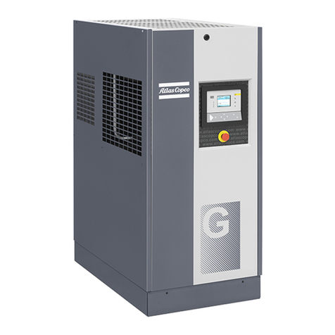
Atlas Copco
Atlas Copco GA 7 VSD+ Instruction book

Gardner Denver
Gardner Denver AirSmart VS20A Operating and service manual
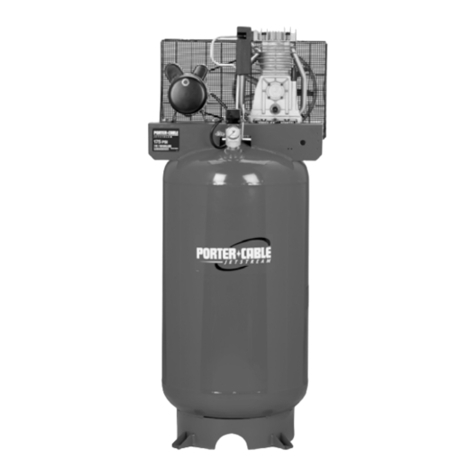
Porter-Cable
Porter-Cable CPLKC7080V2-1 instruction manual
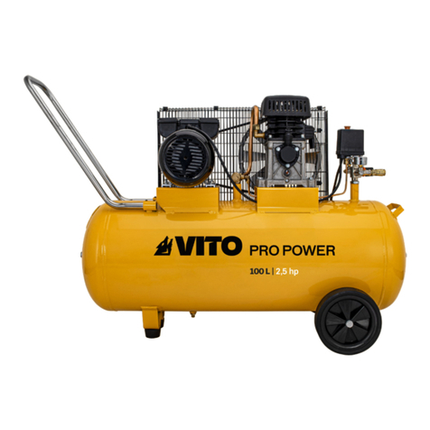
VITO
VITO PRO POWER VICOC50 instruction manual
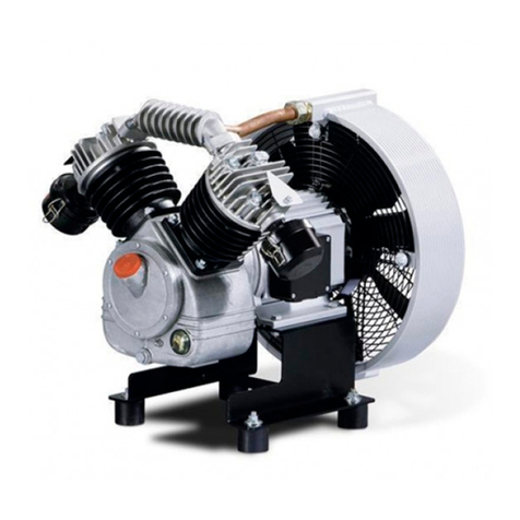
KAESER
KAESER EPC-G Series Assembly and operating manual
