Commtiva Mi350 User manual

E501 L1~L2 Service Document
Version 2.0
E501
L1~L2 Service Manual

E501 L1~L2 Service Document
Version 2.0
2
Contents
Revision..........................................................................................................................................3
1. Specification...........................................................................................................................4
2. General Introduction ..............................................................................................................6
3. Equipment.............................................................................................................................11
4. Exploded View ....................................................................................................................................12
5. Disassembly .........................................................................................................................15
6. Assembly ..............................................................................................................................19
7. FQC mode testing instruction …………………………………..…………………………….… 22
8. SUT Tool …………………………………………...…………...……..………………...….…….… 63
9. UT Help Tool ……….……………………………...…………...……..………………...….…….… 70

E501 L1~L2 Service Document
Version 2.0
3
Revision
Date Version Comment Owner
2011-05-16 V1.0 Initial release of document Bogi Lin
Calvin Dong
2011-05-18 V2.0 1. Add SUT Tool
2. Make-up FQC Test SOP Bogi Lin
2011-05-26 V3.0 Add UT Help Tool Bogi Lin

E501 L1~L2 Service Document
Version 2.0
4
1.Specification
Hardware Platform Specification
Operating System Android Froyo
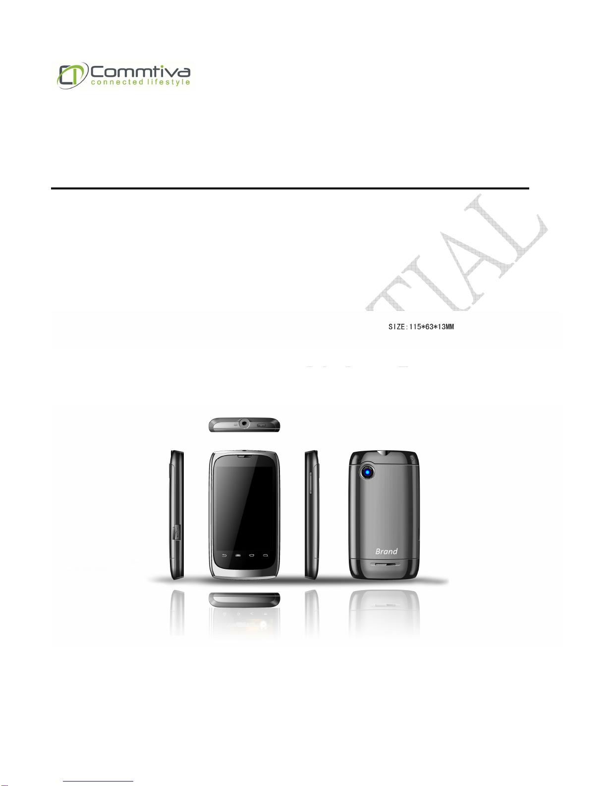
Dimension Size: 114.8mm (H) x 62.8mm (W) x 14.7mm (T)
Weight: 122.5g (device 91g + batt 31.5g)
Processor/Chipset Qualcomm MSM7227-1 with DSDS BSP (App: ARM11 600Mbps)
Memory 512MB NAND Flash/512MB DDR
Display Size: 3.5”
Type: TFT transmissive LCD
Resolution: 480 x 320, HVGA
Color: 18bit, 262K
Touch panel: Capacitive-type touch lens (with LED soft key)
Radio Band & Standard Dual SIM / Dual Standby (WCDMA + GSM)
SIM 1:
GSM/GPRS/EDGE/UMTS/HSDPA
GSM Qual bands: 850/900/1800/1900
UMTS: 900/1900/2100 for EU band, 850/2100 or 850/1900 for US band
GPRS: GPRS Class 12
EGPRS/EDGE: Multi-Slot Class 12
UMTS: DL/UL, HSDPA 7.2Mbps
SIM 2:
GSM Qual bands: 850/900/1800/1900
GPRS: GPRS Class 12
Phone Services Speech with HR/FR/EFR/AMR codec
Call hold/wait/forward
Call History
Call line identification (CLI)
Multi-party conference call
DTMF tone generation
Unstructured Supplementary Service Data (USSD)
SMS class 0/1/2/3
Dual-Mode UMTS-FDD/GSM, UMTS/GSM handover
Preferred network and band selection
Emergency call
PIN1/2, SIM tool kit, SIM lock
Connectivity GPS/AGPS

E501 L1~L2 Service Document
Version 2.0
5
Wi-Fi: 802.11b/g/n
Bluetooth 2.1 + EDR
USB 2.0 High-Speed client (micro-B type)
Audio Built-in microphone, receiver, and loudly speaker
3.5mm audio jack for stereo headset interface
Advanced Echo Cancellation for phone
AAC LC/LTP, HE-AACv1 (AAC+), HE-AACv2 (enhanced AAC+),
AMR-NB, MP3, MIDI, Ogg Vorbis, PCM / WAVE
FM Radio with RDS, RBDS
Video Video playback: H.263, H.264 AVC, MPEG-4 SP
Picture Still image: JPEG, GIF, BMP, PNG
Camera CMOS 5M pixel, Auto focus
Interface micro-USB connector with data sync, power charging features
Micro SD card slot
USIM card slot (Dual SIM slots)
Sensor G-sensor
E-compass sensor
Proximity + Ambient light sensor

E501 L1~L2 Service Document
Version 2.0
6
2.General Introduction
2.1 Feature Diagram
Component Description
Earpiece Serves as the phone earpiece during a call.
Sensors
Touch screen Displays the output of your device. Tap the screen with the stylus to select menu
commands or enter information.
Back Press to return to the previous screen.
Search Press to search for items on the phone or the Internet.
Menu Press to view menu options.
Home Press to return to Home screen.
Microphone An instrument for converting sound waves into electrical energy variations, which may
then be amplified, transmitted, or recorded.

E501 L1~L2 Service Document
Version 2.0
7
Component Description
5 Megapixels
camera Takes pictures or records video clips.
Back Cover To remove or replace the battery, push and slide out the battery cover
Speaker Plays back music, sounds and voice.

E501 L1~L2 Service Document
Version 2.0
8
Component Description
Power Press to turn off the display temporarily. To turn off the power, press and hold for about
3 seconds.
Headset jack A jack of inserted a set of headphones
Component Description
Micro USB
connector Connect the USB data cable to a PC for synchronization of direct Video Out function.
Volume Press to adjust the volume in standard mode.

E501 L1~L2 Service Document
Version 2.0
9
2.2 Installing SIM card and Battery
To remove the back cover
1. Make your device is turned off.
2. Push the back cover up with your
thumb until it disengages from the
device and then slide it up to remove.
To install the SIM card
1. Make sure your device is turned off.
2. Locate the SIM card slot, then insert
the SIM card with its gold contacts
facing down and its cut-off corner
facing out the card slot.
3. Slide the SIM card completely into the
slot.
To remove the SIM card
1. Remove the battery if it is installed.
2. Slide the SIM card out from the SIM
card slot with your thumb.
To install the battery
1. Align the battery’s exposed copper
contacts with the battery connectors
inside the battery compartment.
2. Insert the contact’s side of the battery
first and then gently push the battery
into place.

E501 L1~L2 Service Document
Version 2.0
10
To remove the battery
1. Make sure your device is turned off.
2. Remove the back cover.
3. The top left and right sides of the
battery have protruding grips. Lift a
protruding grip from either side to
remove the battery.
Battery
Your device comes with a rechargeable Lithium-ion or Lithium-ion polymer battery and is designed
to use only manufacturer-specified original batteries and accessories. Battery performance
depends on many factors, including network configuration, signal strength, the temperature of the
environment in which you operate your device, the features and/or settings you select and use,
items attached to connecting ports, and your voice, data, and other program usage patterns.
Battery life estimates(approximations):
Standby time:
Test item & user scenario
Test condition
Life Time(hrs.)
GSM LCD off, measure 3 minutes
468.75
WCDMA LCD off, measure 3 minutes
540.00
Talking time:
Test item & user scenario
Test condition
Life Time(hrs.)
Talking mode (GSM) LCD off, measure 3 minutes
10.98
Talking mode (WCDMA) LCD off, measure 3 minutes
7.89
Note: Battery life is subject to network and phone usage.
Battery grip

E501 L1~L2 Service Document
Version 2.0
11
3.Equipment
STANDARD TOOLS
•Screwdriver ○
+
No.00x50 SNCM
•Tweezers
•Guitar Pick (Thickness 0.8~1.0mm)
ESD EQUIPMENT
Protect the phone from ESD damages whenever it has been
opened by using:
•ESD-wristband
•ESD-gloves
A screwdriver is needed to assemble/disassemble the E501 Case-A, Case-B, metal frame.
We should use electrical screwdriver with ○
+
No.00x50 SNCM. Please notice that the torque is 0.7
kg-cm and driver speed is lower then 750 rpm.
Electrical screwdriver with torque and rotation speed controller.

E501 L1~L2 Service Document
Version 2.0
12
4.Exploded View

E501 L1~L2 Service Document
Version 2.0
13
4.1 Spare part list
Item Level
PN Des Usage
Reference Photo
1 1 20E51XXXXXX001 ASSY KIT_E51CS1_PCBA_EU/US Band 1
2 1 20E51CT0GEN001 ASSY KIT_E51CT0_LCM MODUEL_GEN
1
3 1 20E51CT0GEN004 ASSY KIT_E51CT0_SPK_GEN 1
4 1 20E51CT0GEN005 ASSY KIT_E51CT0_CAM_GEN 1
5 1 20E51CT0GEN006 ASSY KIT_E51CT0_ANT_GEN 1
6 1 20E51XXXXXXXXX ASSY KIT_E51CT0_BATT Cover_GEN 1
7 1 MEE51CT061001A Assy_Case_A_E501 1
8 1 MEE51CT061002A Assy_Case_B_E501 1
9 1 SLP03510X00000 Touch Pannel 1
10 1 S0R26300010000 RCV_32Ω±10%_20mW_15*6*2.5mm 1
11 1 MEE51CT001005A HOLDER_BT_GPS_E501 1
12 1 MEE51CT033011A Sponge_PCBA_Top_E501 1
13 1 MEE51CT033003A Sponge_TP_FPC_E501 1

E501 L1~L2 Service Document
Version 2.0
14
14 1 MEE51CT033009A Sponge_Receive_E501 1
15 1 W6201161750000 Screw_M16_L17_E501
(use for BT antenna) 1
16 1 W6201144050000 Screw_M14_L40_E501
(middle of rear housing) 4
17 1 W6201154550000 Screw_M15_L45_E501
(up/down (2 for each) of case B) 4
18 1 MEE51CT036002A Rubber_LCM_Case_A_Left_E501 1
19 1 MEE51CT036003A Rubber_LCM_Case_A_Right_E501 1
20 1 MEE51CT061004A ASSY_KEY_VOLUME_E501 1
21 1 MEE51CT061005A ASSY_KEY_POWER_E501 1

E501 L1~L2 Service Document
Version 2.0
15
5.Disassembly
Remove the battery cover.
Carefully insert ESD tweezers under one
of the screw caps and then remove it.
Be careful not to scratch the rear bottom
housing.
Use a (○
+
No.00x50 SNCM screw driver)
to remove 6 screws as the figure shown.
There are 8 snap hooks here that have to
unlatch.
Use the pick to disassemble the Case B.
Sequence from Area1 to 3.
Area1.
Area2.

E501 L1~L2 Service Document
Version 2.0
16
Area3.
Use a (○
+
No.00x50 SNCM screw driver)
to remove 6 screws as the figure shown.
Release BT/GPS holder.
1. To tear off TP_FPS sponge.
2. Use front opening tool to disconnect
TP_FPC from PCBA.
Use front opening tool to disassemble
main board.
Remove the main board and TP as the
figure shown.
Be careful the TP_FPC.

E501 L1~L2 Service Document
Version 2.0
17
To tear off PCBA sponge.
Use front opening tool to disassemble
LCM_FPC.
Carefully insert ESD tweezers under one
of the hole and then remove it.
Be careful not to scratch the LCM.
Release the hook of LCM
Be careful the LCM_FPC.
Push the TP lens.
Use front opening tool to disassemble TP
from case A.

E501 L1~L2 Service Document
Version 2.0
18
Disassemble case A and side band.
Be careful the FPC.
Release board to board connector.
1. Use a (○
+
No.00x50 SNCM screw
driver) to remove 2 screws as the
figure shown.
2. Release the GSM antenna.

E501 L1~L2 Service Document
Version 2.0
19
6. Assembly
Assemble case A and side band.
Be careful the FPC.
Assemble case A and TP.
Assemble board to board connector.
Assemble BT/GPS holder.
Use a (○
+
No.00x50 SNCM screw driver)
to lock a screw as the figure shown.
Let LCM_FPC pass throw the side band
hole.

E501 L1~L2 Service Document
Version 2.0
20
1. Assemble the GSM antenna.
2. Use a (○
+
No.00x50 SNCM screw
driver) to remove 2 screws as the
figure shown.
1. Assemble LCM_FPC.
2. Paste the PCBA sponge.
Assemble the main board and TP as the
figure shown.
Be careful the TP_FPC.
Assemble the main board and TP.
Assemble volume keypad on side band
Assemble power keypad on side band.
This manual suits for next models
1
Table of contents
Other Commtiva Cell Phone manuals