ComNav 1420 User manual

1420 Autopilot System
Installation & Operation Manual
COMPLIES WITH
CE REGULATIONS
PN 29010012 V1.3


1420 Autopilot System
Installation & Operation Manual
Document PN 29010012 V1.3

First Printing: January 1993
Revised: June 2000
Revised: January/February/June 2009
Document PN 29010012 V1.3

ComNav Marine 1420 Autopilot System
WELCOME
Congratulations on your purchase of a ComNav Marine 1420 Autopilot System
Autopilot System! At ComNav, we are dedicated to reliability & quality in all our
products, and proud of our prominence as a leader in the design and
manufacture of marine autopilot systems. We promise to do our best to ensure
your satisfaction with your new Autopilot System.
ComNav Marine Ltd.
#15 - 13511 Crestwood Place
Richmond, BC
Canada V6V 2G1
Phone: 604-207-1600
Fax: 604-207-8008
In Canada or the USA
Web Site: www.comnavmarine.com
WARRANTY NOTICE
Prior to the installation and/or operation of the equipment, ensure that you read,
understand, and accept the conditions of the warranties as detailed in the
Warranty Information section of this manual.
OPERATOR’S WARNING
The 1420 Autopilot System Autopilot System will steer your vessel, when you
activate it.
However, it is only an aid to navigation. Its performance can be affected by
many factors including equipment failure, environmental conditions, and improper
handling or use. An autopilot system does not reduce your responsibility for the
control of the vessel when underway. You must always be in a position to
monitor the course, supervise the autopilot, and resume manual control if the
need to do so arises.
Whenever underway, your vessel must be under the
control of a qualified and alert person.
GENERAL NOTICE
This document, ComNav part number 29010012 Version 1 Revision 3, is the approved
Installation and Operation Manual for use with the 1420 Autopilot System Autopilot
System. Where versions of this manual exist in other languages, the English version
shall be considered authoritative.
Document PN 29010012 V1.3
1

ComNav Marine 1420 Autopilot System
Document PN 29010012 V1.3
2
This page is intentionally blank.

ComNav Marine 1420 Autopilot System
TABLE OF CONTENTS
Product Description....................................................................................................................5
Before You Start..........................................................................................................................6
Unpacking and Identification......................................................................................................................... 6
Manual Conventions ..................................................................................................................................... 6
Tools Required.............................................................................................................................................. 7
Parts List ....................................................................................................................................................... 9
Installation Instructions ...........................................................................................................13
1420 Autopilot System ................................................................................................................................13
Planning..............................................................................................................................................13
Processor Location ........................................................................................................................13
Compass Location .........................................................................................................................13
Power Connection ..............................................................................................................................14
Power Cable...................................................................................................................................14
Grounding ......................................................................................................................................14
Installing the Mounting Clip And Spacer ............................................................................................15
Fluxgate Compass Installation............................................................................................................ 15
Rotary Rudder Feedback Installation.................................................................................................16
Outboard Feedback Installation .........................................................................................................19
Rudder Drive ...............................................................................................................................................23
ComNav Reversing-Motor Hydraulic Pump .......................................................................................23
Pump Models & Specifications ......................................................................................................24
Specifications Common to All Pumps............................................................................................24
Types of Steering Systems ................................................................................................................25
Tools and Material Required to Install Pump .....................................................................................25
Notes & Cautions ...............................................................................................................................26
Installing the Pump.............................................................................................................................27
Hydraulic Connections .......................................................................................................................28
Fill And Bleed .....................................................................................................................................30
Wiring the Processor...................................................................................................................................33
Right Side Connections......................................................................................................................34
Left Side Connections ........................................................................................................................36
Connecting the Ground Wire .........................................................................................................36
Connecting the Navigation Cable ..................................................................................................38
Mounting the Processor .....................................................................................................................39
Powering Up the System....................................................................................................................39
Fuse Replacement .............................................................................................................................40
Check the Fuse ..................................................................................................................................40
Setting Up the Autopilot System .................................................................................................................41
Setup Routine.....................................................................................................................................41
Setting Up – Step by Step...............................................................................................................41
Fluxgate Compass Compensation................................................................................................. 43
Magnetic Compass Alignment .......................................................................................................43
Finishing the Setup............................................................................................................................. 43
Document PN 29010012 V1.3
3

ComNav Marine 1420 Autopilot System
Piloting with the 1420 Autopilot System.................................................................................45
Steering Control Settings ............................................................................................................................45
Turning ON the Autopilot:...................................................................................................................45
Turning the Autopilot OFF ..................................................................................................................45
Determining Rudder Response Settings ....................................................................................................46
Setting the Slow Speed Rudder Response........................................................................................ 46
Slow Speed Turns and Course Changes...........................................................................................47
Setting the Fast Speed Rudder Response.........................................................................................48
Fast Speed Turns and Course Changes ...........................................................................................48
The Navigation Interface.............................................................................................................................49
NMEA 0183 ........................................................................................................................................49
Using the Navigation Interface....................................................................................................................50
Cross Track Error ...............................................................................................................................50
Operation Commands ..............................................................................................................51
Adjustment Commands............................................................................................................53
Problem Solving........................................................................................................................54
Problems during the Setup Routine ...................................................................................................54
Problems during Normal Operation....................................................................................................55
Problems during Turn On ...................................................................................................................58
Appendix A ................................................................................................................................59
Connections to 4 and 5 Wire Motors..................................................................................................59
Appendix B ................................................................................................................................60
Connections to 4 and 5 Wire Motors (using a clutch or lockup valve) ............................................... 60
Appendix C ................................................................................................................................61
Connections to Solenoid Valves ........................................................................................................61
Appendix D ................................................................................................................................62
Connecting a Second Station.............................................................................................................62
Appendix E ................................................................................................................................64
Connecting the NMEA 0183 Heading Output.......................................................................................64
Appendix F ................................................................................................................................65
Connecting a Rudder Angle Indicator ................................................................................................65
Warranty ....................................................................................................................................67
CE Compliance..........................................................................................................................71
Document PN 29010012 V1.3
4

ComNav Marine 1420 Autopilot System
Document PN 29010012 V1.3
5
Product Description
The ComNav 1420 Autopilot System has
been designed to make the advantages
of a marine autopilot available to a wide
range of vessels which need accurate
steering control, yet have only limited
space, and require easy installation and
operation.
The 1420 Autopilot contains a feature
called Ghost Rudder. Should the Rudder
Feedback ever fail, the Autopilot will use
its prior knowledge of how the rudder
moves to calculate new “virtual rudder”
positions. While the Ghost Rudder will
not allow the Autopilot to steer as well as
it can with the Rudder Feedback, it will
allow the Autopilot to be used until repairs
can be made.
The 1420 Autopilot System can steer the
vessel on a constant Heading, or along a
Course line.
The 1420 Autopilot is protected against
many mishaps, including: reverse power
connection, output circuitry overload,
computer failure, or program error.
To steer a constant Heading, the
Autopilot compares the compass
information with the Heading (Course)
that the operator has selected. If the
vessel is not on the correct Heading, the
Autopilot calculates the rudder position
which will bring the vessel onto the
correct Heading.
The 1420 Autopilot features pushbutton
steering control, course correction as
small as one degree, two independent
rudder response settings with 14
sensitivity settings in each, a navigation
interface, and watertight construction.
The Autopilot uses the vessel’s steering
system to move the rudder (or outboard
motor) to the position it calculates. The
steering system may be a hydraulic
system, or an electric motor, and
mechanical linkage. Information from the
Autopilot’s Rotary Feedback (or Outboard
Feedback) is used to calculate new
rudder positions, and to verify that the
steering system has followed the
Autopilot commands.
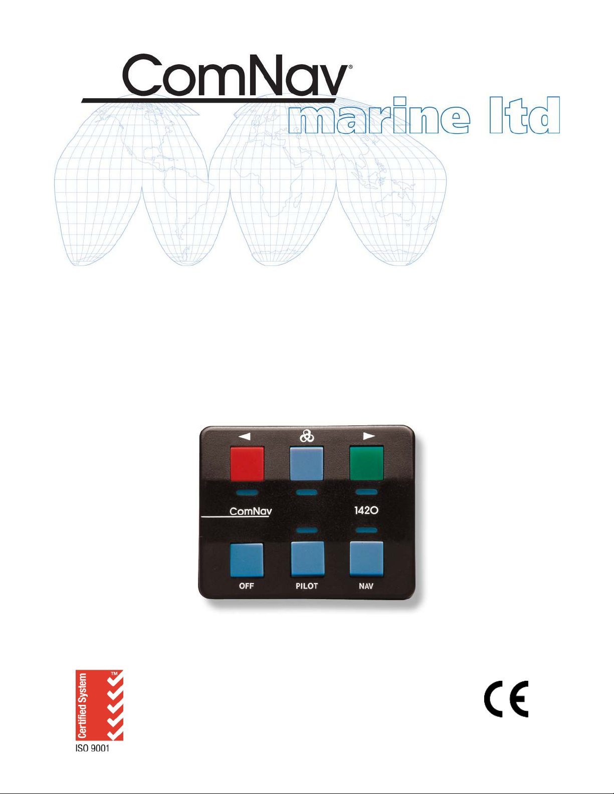
The Control Head can be mounted on a
panel using a supplied Clip. When
removed from the Clip, it can be used as
a portable unit.
Specifications
Voltage: 10 VDC - 40 VDC
Steering Outputs: 20 Amperes Maximum
Dimensions L x W x H or D
When steering along a Course line, the
1420 Autopilot System uses information
from the compass to monitor the vessel’s
heading. It can also use position
information received in NMEA 0183
format from a GPS receiver, a
chartplotter, or other device. Using both
of these inputs, the Autopilot calculates
the Course to Steer which will keep the
vessel on the Course line.
Control Head: 3.1 x 2.5 x 0.7 inches
(7.9 x 6.4 x 1.8 cm)
Processor: 15 X 6.3 X 2.7 inches
(38.1 x 16.0 x 6.9 cm)
Compass: 5.6 x 3.0 x 4.2 inches
(14.2 x 10.7 x 7.6 cm)
Pump: 7.5 x 4.75 x 4 inches
(19.0 x 12.2 x 10.2 cm)

ComNav Marine 1420 Autopilot System
Before You Start
Thank you for buying the ComNav 1420
Autopilot System. It will make boating
safer, easier and more enjoyable for you!
Please do not forget to complete and
send in your warranty card.
This will give you 3 years of Warranty
protection. We suggest that you do it
first!
Happy boating!
Unpacking and Identification
Please make sure that you have found
and identified all of the components of
your Autopilot System, before you begin
installation. This manual begins with a
parts list, to help you identify the
components of your system.
Your system will have either a Rotary
Rudder Feedback or an Outboard Motor
Feedback. There are separate sections
about both Feedback units in this manual.
If you purchased a system without a
Hydraulic Pump, you can ignore the
sections of the manual dealing with
Pumps, and about bleeding the hydraulic
system.
Wiring diagrams for connecting to 4 and 5
wire motors and solenoid valves are in
the appendixes.
Manual Conventions
In this manual, the names of the main
components are capitalized.
For example: Processor
Also, the keys on the Control Head are
capitalized.
For example: Speed Key
When you are required to perform an
action with a key, it is underlined.
For example: Press the Red Key
When you are to look for a Control Head
light to turn on, it will be underlined.
For example: light beneath the
Green Key
Document PN 29010012 V1.3
6

ComNav Marine 1420 Autopilot System
Document PN 29010012 V1.3
7
Tools Required
The general tools & other items you will
need while installing the system are:
1) Basic Tool Kit
2) Screwdrivers: One Phillips, one
slot-head
3) Wire Cutters: a pair of ordinary wire
cutters suitable for general electrical
work will do
4) Drill and a selection of Drill Bits
5) Small Adjustable Wrench
6) Any tools specific to your boat
7) Miscellaneous fasteners & mounting
hardware, for mounting components
and securing hydraulic lines (see
individual “installation” sections,
below, for specific suggestions)
8) You may also wish to have a supply
of Ty-wraps (aka “zap straps”) for
securing electrical cables
If you purchased a 1420 with a Hydraulic
Reversing Pump, a list of the tools you
will require specifically for the installation
of the Reversing Pump is on page 25.
If you purchased a 1420 with a Rotary
Rudder Feedback you may need one
stainless steel band clamp, of a size more
than large enough to fit around your
vessel’s rudder post. See page 16.

ComNav Marine 1420 Autopilot System
1420 System Diagram
Document PN 29010012 V1.3
8

ComNav Marine 1420 Autopilot System
Parts List
Note: Parts are not drawn to any scale.
Processor. PN 20070003
Control Head. PN 20070002. This part includes 25 feet (7.6 m) of
cable wired to it.
Control Head Mounting Clip and Spacer (these are included in the
Accessory Kit). PNs 65610066 & 65610067 (can also be ordered
together as PN 30070002, if additional Head mounting locations are
desired).
Document PN 29010012 V1.3
9

ComNav Marine 1420 Autopilot System
Document PN 29010012 V1.3
10
ComNav Fluxgate Compass. PN 20320003. This
has 40 feet (12.2 m) of cable wired to it; the other
end of the cable has stripped & tinned wires.
If you purchased a system with a Heading Rate
Stabilizer, you will instead have a Fluxgate
Compass PN 20320004, which has a 7-pin plug on
the cable’s end. The Compass plugs into the HRS.
The HRS is PN 20320009, and has 40 feet
(12.2 m) of cable wired to it; the other end of the
cable has stripped & tinned wires. Installation &
wiring instructions for the HRS are included with it.
One of two different Feedback Units will be included:
Rotary Rudder Feedback. PN 20330008. This part
includes 50 feet (15.2 m) of cable wired to it.
This part always comes with:
Rotary Rudder Feedback Linkage Kit. PN 20330007.
or:
Outboard Feedback. PN 20330002. This part includes
30 feet (9.1 m) of cable wired to it.

ComNav Marine 1420 Autopilot System
Also included but not shown:
•Power Cable. 7.5 feet (2.3 m) of cable (labelled “5”), for connecting supply voltage
to the Processor.
•Accessory Kit. PN 20070004. Contains extra terminal sockets, a cable gland and
the Control Head Mounting Clip & Spacer.
•1420 Installation & Operation Manual (this manual, PN 29010012).
If you purchased a system with a ComNav hydraulic pump, one of two models, at one of
two operating voltage ratings, will be included. All the pumps look very similar, so inspect
the labels carefully.
•18CI Reversing Pump, 12 VDC. PN 20810016
•18CI Reversing Pump, 24 VDC. PN 20810031
•30CI Reversing Pump, 12 VDC. PN 20810018
•30CI Reversing Pump, 24 VDC. PN 20810035
All pumps have 20 feet (6.1 m) of cable wired to the
Pump Motor.
If you purchased a system with a Cable Drive, one of several models will be included. The
models vary slightly in appearance, so inspect the labels carefully.
•Type 'S' (Morse Straight Shaft – shown in the figure).
PN 20910002
•Type 'MTS' (Morse Tilt Shaft). PN 20910003
•Type 'T' (Teleflex Performance Tilt). PN 20910004
•Type 'TST' (Teleflex Standard Tilt). PN 20910005
•Type 'R' (Remote). PN 20910009
Document PN 29010012 V1.3
11

ComNav Marine 1420 Autopilot System
This page is intentionally blank.
Document PN 29010012 V1.3
12

ComNav Marine 1420 Autopilot System
Document PN 29010012 V1.3
13
Installation Instructions
Caution
Using ordinary electric tools near water is VERY dangerous! To minimize the dangers of
electric shock and personal injury, we recommend using only cordless rechargeable tools,
and/ or hand tools, during the installation of the system.
1420 Autopilot System
Allow at least a foot (30 cm) of clearance
on either end of the Processor in the
space where it is to be located.
Planning
Processor Location
In choosing a location for your ComNav
1420 Autopilot System, remember that
the cable from the Control Head to the
Processor (Cable #1) should not be cut or
lengthened. Excess cable may be
loosely coiled behind a panel.
Do not mount the Processor near heat
sources, such as heat radiators, or over
engines.
If you can, mount the Processor so that
the cooling fins are vertical.
You will want to have the Control Head
near the steering station you use the
most; place the Mounting Clip at this
station. Also note the following, when you
plan the routing of cable #1:
If possible, mount the Processor where
you will be able to hear its internal beeper
while operating your boat. Although the
lights on the Control Head will tell you
about the Autopilot's actions, it helps if
you can hear the beeper too.
- Cable #1 is 25 feet (7.7 m) long, and
is permanently attached to the
Control Head. Compass Location
When choosing a location for the
Compass, try to locate it as close as
possible to the most stable spot on your
boat. Usually this spot will be close to the
water line level, in the middle of the boat
and two-thirds towards the stern from the
bow.
- If you are intending to move the
Control Head around, in order to use
it in other locations, locate the
Processor so that the Head’s cable
will also be able to reach those other
locations.
Similarly, the cable from the Compass to
the Processor (Cable #2), should not be
cut or lengthened. Cable #2 is 40 feet
(12.2 m) long (excess may be coiled up).
Do not install your Compass near wires or
devices carrying large electric currents
such as battery chargers, electric pumps
and motors or televisions.
Do not mount your Compass near any
iron or steel objects.

ComNav Marine 1420 Autopilot System
Power Connection
There is 7.5 feet (2.3 m) of power cable
included with your Autopilot System. We
recommend that you do not lengthen this
cable.
However, if you must extend the cable:
•Use the shortest extension length
possible; it must be less than 10 feet
(3 m) in length.
•Use no less than #10 or 12 AWG
conductors. Splice and solder the
joints.
•Make the joints watertight by using
heat-shrink tubing and silicon, or
some other watertight covering.
Power Cable
The Power Cable is labelled with a "5".
Connect the Power Cable to a breaker
capable of supplying at least 20 Amperes
at 12 Volts DC.
The white wire is for Battery Positive from
the breaker. The black wire is Battery
Negative. The green wire must be wired
to the ground point (see Grounding,
next).
Route Cable #5 to the Processor location.
Keep the breaker turned off until you
have connected the wires to the breaker.
Grounding
The Power Cable also contains a
grounding wire. Connecting this wire to a
good ground (see * below) may reduce
static on radios and improve GPS
reception.
Many different grounding methods can be
used:
1. If you have a small vessel, the
negative battery post can be used.
•If you have several electronic
instruments, each must be
attached to the battery individually.
Do not connect one instrument to
another and then to the battery
post.
2. If you have a ground plane for a radio
on your boat, connect the ground wire
to that ground plane.
* A proper ground connection point must
be at the same voltage level as battery
negative. Any difference in voltage
between battery negative & the ground
point may indicate a problem in the
wiring, and so the ground-point wiring
must be re-done, or replaced. Ensure
that all ground connection wires are as
short as possible, and that all connectors
are clean.
Document PN 29010012 V1.3
14

ComNav Marine 1420 Autopilot System
Installing the Mounting Clip And
Spacer
Head Mounting Clip and Spacer
The Mounting Clip is used for mounting
the Control Head. The design of the Clip
allows two methods of placing the Control
Head cable.
•Using the Clip and the Spacer, the
cable can run out loose from the
bottom of the clip.
•Using only the Clip, the cable can
be run straight back through a hole
in the mounting surface.
If the cable is brought through a hole in a
panel, you can store the excess cable
behind the panel. If you want to move the
Head to another position, you can pull the
cable out as needed (and you can buy
additional Clips for those other locations –
see page 9).
The usual mounting spot is on the
dashboard within easy reach when you
are steering your vessel.
The Clip is mounted using four # 10
(5 mm) fasteners (supplied by you: use a
corrosion-resistant type, and a style &
length suitable to the mounting surface).
Use the Clip as a template to mark the
holes.
Fluxgate Compass Installation
Fluxgate Compass
The fluxgate compass must be correctly
positioned or it will not work.
To correctly position the Fluxgate
Compass, mount it so that the top surface
(with the cable gland) is up.
On the top surface there is an arrow
labelled "bow". The arrow must point in
the same direction as the bow of your
boat.
In cases where the compass is mounted
on a side wall, the bow line arrow will be
pointing to Port or Starboard. If so,
remove the four screws in the top of the
case, rotate the bottom part of the case ±
90 degrees, as needed so that the arrow
points to the bow; then re-fasten the top
to the bottom with the 4 screws.
Warning: This compass is designed
to be watertight. Be careful with seals
and “O” rings, if you remove the
case’s top to correct for a side-wall
mounting.
Initially, mount your Fluxgate Compass
using strong adhesive tape or some other
temporary, non-marking fastener. The
reason for this is that It may be necessary
to relocate your compass after you have
done the Setup Routine.
Once the compass setup is completed,
the compass’s case can be securely
fastened down with suitable fasteners.
Document PN 29010012 V1.3
15

ComNav Marine 1420 Autopilot System
Rotary Rudder Feedback Installation
If you have a 1420 Autopilot System with an Outboard Feedback, please go to page 19.
Select the following parts from the 1420 Autopilot package:
You may also need:
•one stainless steel band clamp to hold the Rudder Arm to the rudder post
•four screws: #10 size (5 mm), suitable length, to fasten down the Rudder Feedback
Install the Rudder Feedback in the stern of the vessel, close to the rudder post. Place the
Rudder Feedback so that it will be protected from objects which may shift position when
your boat is moving.
Brass Ball Joint
(Included with linkage)
PN 65520006
Rudder Feedback
PN 20030008
Linkage Rudder Post Arm
PN 65520004
PN 65520051
Document PN 29010012 V1.3
16
Table of contents
Other ComNav Autopilot System manuals
Popular Autopilot System manuals by other brands

Navman
Navman G-PILOT 3100 Operation manual

Raymarine
Raymarine SmartPilot X-5 ST6002 Controller Quick reference guide

TruTrak
TruTrak Vizion PMA Autopilot Operating handbook

Axair
Axair MIAP manual

Furuno
Furuno NAVpilot-500 installation manual

Garmin
Garmin GHP Compact Reactor Hydraulic installaiton instructions