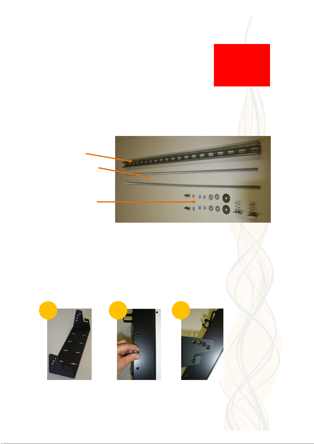
Concept Smoke Screen SENTINEL S30 User manual

Page 1of 16
SENTINEL S30
INSTALLATION AND OPERATION
MANUAL
(Version 16 December 2013)
CAN’T SEE IT? CAN’T STEAL IT!

Page 2of 16
Thank you for purchasing a Concept Smoke Screen system. Your choice to protect your property and
premises with this equipment has given you the use of one of the most effective security systems currently
available. Concept Smoke Screen systems have been in service for over 35 years and have protected many
millions of pounds worth of property, defeating criminals and securing premises on an almost daily basis.
Please take the time to read and understand this guide to ensure you achieve the maximum performance
from your Smoke Screen. If you have any questions that remain unanswered, please call our experts at
Concept Smoke Screen and we will help. Once again, thank you for your decision; we hope that it's one that
never needs to be tested.
Carl Gibbard, Managing Director
HOW DOES YOUR SMOKE SCREEN WORK?
Your Smoke Screen heats a non-toxic fluid under pressure to create smoke, or more accurately a
thermally generated fog, that obscures visibility to discourage intruders from entering your
premises.
This fog is very persistent and will stay suspended in the room for a significant length of time until it
is vented by opening the doors and windows.
The Smoke Screen uses a sophisticated electronic control system to ensure it heats up to, and
maintains, its ideal operating temperature using a minimal amount of electricity.
This control system similarly provides a flexible interface with intruder detectors and alarm systems
to ensure that you are always protected and free of inadvertent activations.

Page 3of 16
CONTENTS
Subject
Page
How does your Smoke Screen work?
2
Introduction
4
Overview
4
Standard installation
4
Positioning
5
Installation procedure
5
Access
6
Mounting
6
Controlling the smoke
7
Circuit board layout
8
Generic connection diagram
8
Un-interrupted Power Supply (UPS)
9
Tamper
9
Fluid management
9
Programming
10
Operation
10
Testing
11
LED and sound indications
12
Action after every activation
13
Servicing and fluid replenishment
13
FAQ
13
Installer notes
14

Page 4of 16
INTRODUCTION
Before commencing installation of the Smoke Screen ensure that you have all of the following
equipment supplied in the box:
1 x Smoke Screen
1 xWall Mounting Bracket
1 x Smoke Fluid Bag (Boxed)
1 x LiteraturePack & Warning Sign
You will also require:
230-volt mains supply andconnections into the Alarm Panel or other triggering system.
PIR (or equivalent)to provide the hold-off where required.
OVERVIEW
The Smoke Screen is designed to form part of an existing intruder alarm system but may also be
configured as a ‘stand-alone’ system. A ‘standard’ installation is shown in the following schematic:
STANDARD INSTALLATION
A ‘standard’ installation is configured in the following way:
The Smoke Screen wall or ceiling mounted in the appropriate location.
A Hold-off PIR (or similar device) located within the same area as the Smoke Screen providing a
confirmation signal to theSmoke Screen to start ‘smoke’ production.
A Set command supplied by an Alarm Control Panel, or equivalent, in the form of an N/C (Normally
closed) relay opening when the Alarm system is set for operation.
A Trigger command supplied by the Alarm Control Panel, or equivalent, in the form of an N/C
(Normally closed) relay opening when the Alarm system confirms an intruder alert.
Remote
Keypad
Intruder Alarm
Control Panel
Alarm Hold-off
PIR (or similar)
Alarm Hold-off
Micro switch
Intruder
Status
Verification
Secondary
User
Interface
Set
Smoke
Screen

Page 5of 16
POSITIONING
The Smoke Screen should ideally be sited in a covert position away from prying eyes and thereby
reducing the possibility of tamper or an attack. The ideal place for the Smoke Screen is above a
ceiling from where the smoke plume is used to its best effect, bursting on the ground and
spreading outwards and upwards through 360°. If no suitable ceiling location is available then the
next best location is a wall mounting as close to ceiling height as possible.
Wall-mounting.
The optimum wall mounting position for the Smoke Screen is 2.5 metres above the floor facing the
area to be protected and using an appropriate angle nozzle. The maximum mounting-height above
floor level is 3 metres, the minimum is 1 metre and there should be no obstacle within 1 metre of
the smoke output nozzle.
Ceiling-mounting.
The optimum ceiling mounting height for the Smoke Screen is 2.5 metres above the floor over the
area to be protected and using a straight nozzle. The maximum mounting-height above floor level
is 3 metres and there should be no obstacle within 1 metre of the smoke output nozzle.
INSTALLATION PROCEDURE
1. Site the Smoke Screen and fix the bracket to the wall or ceiling as appropriate.
2. For wall mounting leave minimum 150mm clearance to ceiling.
3 Fasten the Smoke Screen to the bracket and open front cover.
4. Make connections as required to the Alarm Panel and Hold-off PIR.
5. Make connection to the Exagon panel (if used) and set the key switch to isolate mode.
6. Connect mains power (230-volt AC, 50Hz).
7. The Smoke Screen will heat up to operating temperature in approximately 20 minutes.
8. Ensure that the smoke time is set for the specified room size; the UPS system is set as
required; and the programming dip switches are in the correct position.
9. With the power applied insert fluid bag and make sure the fluid switch is closed correctly.
10. Ensure all covers are fitted and tamper switches are closed. You are ready for test.
X
<1.0 metre
X
>3.0 metres
2.5 metres
✓
✓
2.5 metres

Page 6of 16
ACCESS
To access the PCB connections and programming buttons (fluid bag
access covered in the relevant section) remove the front cover by
unscrewing the 2 set screws on either side and the 2 countersunk set
screws in the top; refitting is the reverse process. Installation cable
entry is through the grommet on the top, right back of the case.
MOUNTING
The Smoke Screen can either be ceiling mounted, or wall mounted, using the bracket supplied. If
ceiling mounted, it is recommended that the Smoke Screen is suspended on 2 lengths of M8 studding
from a Unistrut section (pictured). In all cases, the installer must fit the Smoke Screen using appropriate
fasteners.
Suspension Kit (All M8)
Uni-strut 1 x 1 metre
Threaded bar 2 x 1 metre
Fixings: 2 x 38mm washer
4 x 25mm washer
6 x full nut
2 x drop-in anchor
2 x channel nuts,
Wall mounting
The Smoke Screen can be wall mounted to fire horizontally, or angled to fire down at 15, 30 or 45
degrees, using a simple wall bracket (1) that should be attached to a suitable wall using
appropriate fixings. We recommend as high a position as possible for aesthetic and security/anti-
tamper reasons, but no higher than 3 metres above the floor. Select the most appropriate one of
the 2 pairs of threaded holes on each side of the Smoke Screen and insert a set screw a few
threads into the bottom hole on each side (2). Carefully locate the Smoke Screen on to the bracket
by sliding the bottom set screws in to the wall bracket hooks and then insert one set screw on each
side to lock the unit at the required angle (3). Tighten all four set screws.
NOTE
If the Smoke Screen
has been in service
the heater block will
be extremely hot and
will cause injury if
touched.
1
2
3

Page 7of 16
Suspension mounting
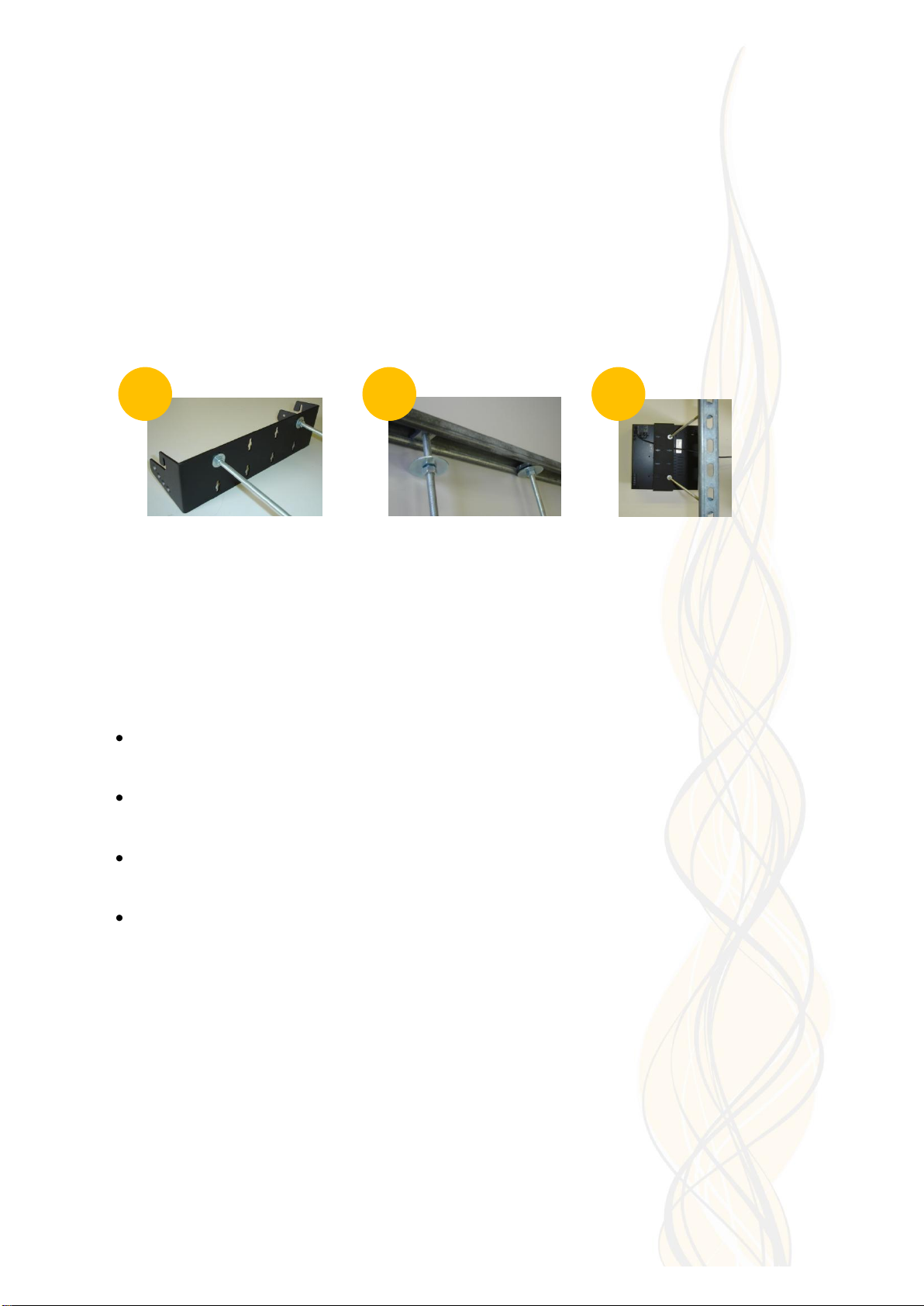
Suspending the Smoke Screen range is achieved using the ‘Suspension Kit’ comprising a length of
Uni-strut, two sections of threaded bar and fixings. Fix the required length of M8 threaded bar to
the wall bracket (use the holes in line with the bracket hooks) using 4 x nuts and 4 x 25mm
washers (4). Fix the uni-strut into place. There are a range of fixings to accommodate concrete
ceiling, girders etc; if in doubt contact the fixing supplier. Attach the threaded bar to the uni-strut
using the channel nuts, 38mm washers and M8 nuts (5). Insert a set screw a few threads into the
lower hole of the top pair of threaded holes on each side of the Smoke Screen (2). As described
under “Wall Mounting”, lift the Smoke Screen into position and insert another set screw on each
side to lock the unit in the ‘non-angled’position. Tighten all four set screws. Any final adjustments
to height can be made at this stage as the nuts and the threaded bar will take the weight of the
Smoke Screen. The final assembly, viewed ‘through the ceiling’ is in photo (6).
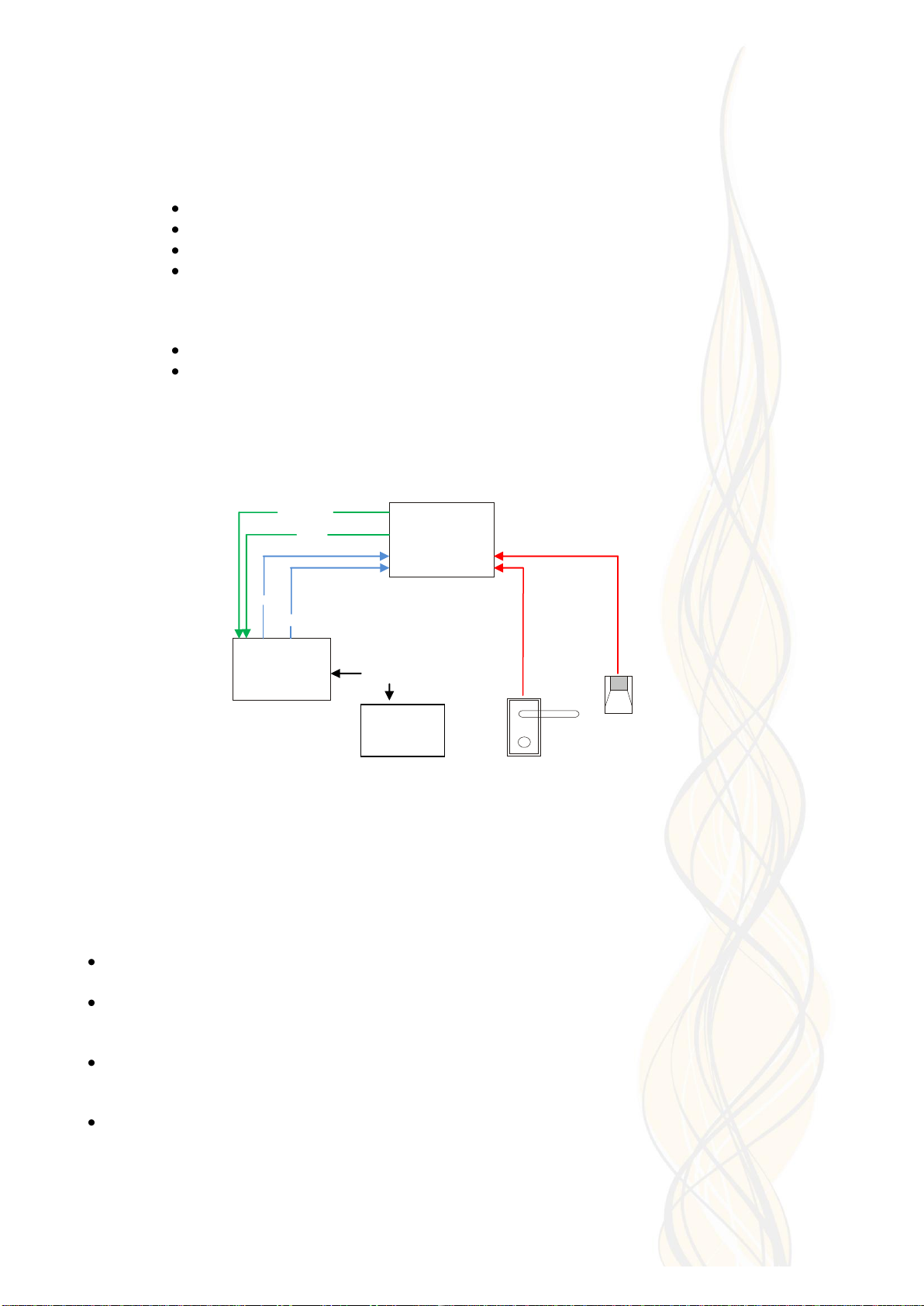
CONTROLLING THE SMOKE
Inputs. There are 3 setsof input connections on the Smoke Screen (Alarm Set, Trigger and Hold Off)
that should be connected to clean contacts. For theSmoke Screen to produce ‘smoke’ all 3 sets of
connections must be ‘open circuit’ (this can be changed to ‘closed’ as described under ‘Trigger Mode’ in
the ‘Programming’ section).If one set of connections is ‘closed circuit’ then the Smoke Screen is
prevented from producing smoke. Hence the production of smoke is controlled using one or a
combination of the following:
Alarm Set –a normally closed relay connected across the Alarm Panel ‘Set’ connections, which
open when the Alarm Panel is ‘Set’ and closing when the panel is ‘Unset’.
Trigger –a normally closed relay connected across the Alarm Panel ‘Trigger’ or ‘Intruder’
connections, which open when the Alarm Panel is in ‘alarm’.
Hold-off –usually a PIR or movement sensor connected to the ‘Hold-off PIR’ connections (N/C),
which opens when the sensor sees movement.
Additional Hold-off –any form of N/C relay or micro switch can beconnected to the ‘Hold-off’
connections. Where fitted in addition to the Hold-off PIR both sets of relays must be ‘open’ to
produce ‘smoke’.
Outputs. Outputs are provided for connection to the Alarm Panel for ‘Ready’, ‘Low Fluid’, ‘UPS
Status’ and ‘Verification Output’. See the notes on the “Generic Connection Diagram” for the
function of these outputs.
4
5
6

Page 8of 16
CIRCUIT BOARD LAYOUT
PCB Connection Terminals
Mains fuse (10 Amp)
Tamper Jumper
Programming Dip Switches 1 & 2
Activation test button“PB1”
Programming button “PB2”
Indication LED
GENERIC CONNECTION DIAGRAM
20130828-S30 Generic Connection Diagram-v2
●
Tamper
●
Tamper
●
0v (100mA)
●
12v (100mA)
●
Hold Off
●
Hold Off
●
Verification NO
●
Verification NC
●
Verification COM
●
UPS Status NO
●
UPS Status NC
●
UPS Status COM
●
Fluid Status NO
●
Fluid Status NC
●
Fluid Status COM
●
Not Ready NC
●
Not Ready NO
●
Not Ready COM
●
Trigger
●
Trigger
●
Alarm Set
●
Alarm Set
S30 Generic Connection Diagram
PIRor other
S30 Notes
final confirmation device
Tamper
Tamper
Tamper
Tamper
0v
0v DC
12v
12v DC
Alarm Panel or similar control device Alarm
Hold Off
Alarm
Hold Off
Input 1 +ve Verification n/o
Machine activating Verification n/c
Ground
Verification com
Input 2 +ve UPS n/o
UPS failure UPS n/c
Ground
UPS com
Input 3 +ve Low n/o
Fluid low Low n/c
Ground
Low com
Input 4 Ready n/c
Machine ready +ve Ready n/o
to activate Ground Ready com
Set
Trigger
Set
Trigger
Intruder
Alarm
Intruder
Alarm
"Tamper" changes state if the S30 case or external tamper
is open. n/c and n/o shown are when the case is closed.
Outputs
"Ready" changes state if there is a critical fault. n/c and n/o
shown are when the S30 is working correctly.
"Low" changes state if the S30 fluid is low. n/c and n/o
shown are when there is fluid available.
"UPS" changes state if there is a UPS fault. n/c and n/o
shown are when the UPS is working correctly.
Alarm Panel detects n/o
circuit going closed to
signalthe specified event.
Alarm Panel ouput contacts
should be clean relay
closed pairs energising
open on set / intruder.
"Verification" changes state when the S30 fires. n/c and
n/o shown are when the S30 is not firing.
"AlarmSet", "Trigger" and "Hold Off" should be connected
to normally closed clean contacts going open to fire the
S30. All3 must be open to fire the S30.
DCoutput for additional device. Total S30 output must not
be greater than 100mA.
See note for "AlarmSet" and "Trigger". Leave open if no
device fitted.

Page 9of 16
UN-INTERUPTED POWER SUPPLY (UPS)
If required a UPS, or maintained, supply can be incorporated into an installation through the IEC panel
plug on the case. When the mains supply fails this will provide power to the electronic circuits and pump
(not to the fluid heater) to ensure that for 1 hour after a mains power failure the Smoke Screen can
provide a full smoke activation. Enabling the UPS monitoring system is described in the “Programming”
section. If the UPS supplyfails the Smoke Screen operates normally when a mains supply is available.
Mains Power Loss (No UPS connected). When mains power is restored after a temporary power loss
the Smoke Screenwill be automatically disabled for 60 seconds toallow the Hold-off PIR tostabilise
and prevent theSmoke Screenfrom firing in the event of a false panel alarm.
TAMPER
There are 3 tamper circuits on the Smoke Screen, one on each cover (front and fluid) and an
external tamper input on PCB. The external tamper input can be disabled if not in use by placing a
jumper on the pins marked on the photograph in the “Circuit Board Layout” section. A tamper
‘open’ state does not prevent the Smoke Screen from activating.
FLUID MANAGEMENT
Fluid capacity. The Smoke Screen can be fitted with a 500ml transparent bag containing ‘Smoke
Fluid’.
Fluid monitoring. The Fluid Level is monitored using an on-boardtimer that measures the amount of
fluid used bytiming consumption when the Smoke Screen is activated. Eachtime the bag clamp is
unfastened and the fluid bag is replaced the micro switch is cycled which resets the timer and the
Smoke Screen will calculate this as a new fluid bag.
Changing a fluid bag: Ensure that power is applied to the Smoke Screen. Open the fluid access
panel in the top of the Smoke Screen. Unscrew the bladder neck holder retaining screw and the
bag support screw. Push the fluid probe into the “out” position in the bag neck (1). Place the other
end of the bag onto the support and insert the retaining screw.
Carefully locate the bag neck in the correct position in the cradle (1 & 2). Close the retaining gate
and insert the retaining screw (3). Ensure the bag neck is held correctly and the fluid micro switch
is activated properly.
ALWAYS REPLACE A FULL FLUID BAG EVERY TIME THE FLUID BAG HOLDER MICRO
SWITCH IS RESET. FAILURE TO DO SO MAY RESULT IN DAMAGE TO THE SMOKE FLUID
PUMP.
WHEN ANEW FLUID BAG IS FITTED POWER MUST BE APPLIED TO THE SMOKE SCREEN TO
RESET THE FLUID TIMER.
2
3
1

Page 10 of 16
PROGRAMMING
Smoke Time. The length of time that the Smoke Screen will produce ‘smoke’ can be varied
between 15 seconds and 6 minutes. The delivery smoke time setting is 15 seconds, which is
equivalent to approximately 75 cubic metres of smoke. The smoke time is set as follows:
Change Dip Switch 2 to ‘ON’ (LED should alternate Red / Green to indicate in programming
mode).
Press the ‘PB1’ button for 10 seconds. When the buzzer beeps twice the timer is set to 15
seconds.
Each subsequent press of the ‘PB1’ button will extend the smoke time by 15 seconds, up to
a maximum of 6 minutes.
When the required smoke time setting is reached change Dip Switch 2 to ‘OFF’.
If a mistake is made in programming the run time change Dip Switch 2 to ‘OFF’ and start
again.
UPS Monitoring. The Sentinel S30 can be set to monitor the UPS (if fitted) and enable the UPS
relay output. To alternate UPS monitoring between on and off follow this procedure:
Change Dip Switch 2 to ‘ON’ (LED should alternate Red / Green to indicate in programming
mode).
Press ‘PB2’ for 10 seconds. When the buzzer beeps twice the UPS monitoring has been
changed between on and off.
When finished change Dip Switch 2 to ‘OFF’.
Note: If there is a UPS fault or no UPS is fitted the LED will flash twice every 5 seconds
accompanied by 3 short beeps every 30 seconds.
Trigger Mode. The delivery settings of the 3 sets of input connections on the Smoke Screen
(Alarm Set, Trigger and Hold Off) are normally closed going open to activate (Dip 1 set to ‘ON’).
These can be changed to normally open going closed to activate by changing Dip 1 to ‘OFF’.
OPERATION
While the Smoke Screen is heating upthe LED indicator will be Red. If any of the access panels are
open the LED indicator will flash yellow once every 5 seconds; a tamper indication will prevent the
Smoke Screen from producing smoke. When the Smoke Screen reaches the correct working
temperature, all tamper circuits are closed and a full Smoke Fluid Bag has been correctly installed, the
LED Indicator will goGreen.
Stopping smoke. If the ‘Hold-Off’ is closed during an activation the Smoke Screen will continue to
produce smoke for the set Smoke Time. An activation can only be stopped by closing the ‘Alarm Set’
and/or the ‘Trigger’.
Re-triggering smoke (Hold-off attached).If, after it has made smoke for the pre-set time, theSmoke
Screen receives another hold-off alarm with open ‘Alarm Set’ and ‘Trigger’ inputs it will ‘re-trigger’ and
make smoke again.

Page 11 of 16
TESTING
Full alarm test. Where possible a full alarm test should be conducted to check that all inputs, outputs
and wiring connections to the Smoke Screen are correct. If a PIR or other detector is fittedthe Smoke
Screen will firefor the designated Smoke Time period once the ‘Alarm Set’, ‘Trigger’ and ‘Hold Off’ (if
fitted) contacts are open. It will stop producing smoke if the ‘Alarm’ or ‘Trigger’ contacts are closed.
Smoke Screen stand-alone test. The Smoke Screen can be tested when it is ready to operate
(indicated by a steadygreen LED) by pressing the button on the PCB marked “PB1”. This produces
smoke only whilst the button is pressed. NB: this does not check that the inputs and connections
to the Smoke Screen are correct.
Note. When mains power is switched on, even if the Smoke Screen is alreadyat operating
temperature, it will be automatically disabled for 60 seconds to allow the Hold-off PIR to stabilise and
prevent the Smoke Screen from firing in the event of a false panel alarm.

Page 12 of 16
LED AND SOUND INDICATIONS
The Smoke Screen provides on-board statusmonitoring via an LED and a sounder. Indications displayed are:
LED colour
Buzzer sound
Output relay status
change
Indication meaning
●
Flash twice every 2 seconds
1 short beep every 5 seconds
Ready n/c to open.
Smoke Screen overheating*.
●
Flash once every 2 seconds
1 long beep every 60 seconds
Ready n/c to open.
Cover open and/or the external tamper is open/not jumpered.
●
Flash twice every 5 seconds
1 short beep every 5 seconds
UPS n/c to open.
UPS monitoring set to on and UPS power fail or UPS not
connected.
●
Flash once every 5 seconds
1 short beep every 5 seconds
Nil.
Mains power failure (UPS fitted).
●
Flashing
1 short beep every 5 seconds
Ready n/c to open.
Heater fault*.
●
On
Continuous beep for 30
seconds then 3 short beeps
every 5 minutes
Nil.
Smoke Screen heating to operating temperature*.
●●
Alternating
None
Nil.
Smoke Screen in ‘Programming Mode’.
●
On
None
Ready n/c to closed.
Smoke Screen ready to operate.
●
Flashing
None
Nil.
Smoke Screen receiving ‘Alarm Set’ and ‘Trigger’ signals but
waiting for a ‘Hold Off’ to activate.
●
Flashing
1 beep every 2 seconds
Verification n/c to open.
Smoke Screen has activated and smoke has been produced
–indication will continue until both ‘Alarm Set’ and ‘Trigger’
are reset.
●
On
1 short beep every 5 minutes
Fluid status n/c to open
Low fluid –first warning, Smoke Screen will still activate.
●
Flashing
1 long and 1 short beep every
5 minutes
Nil.
Empty fluid or fluid bag removed*.
* = Smoke Screen will not activate in this state.
Once resolved, any remaining fault indications can be cleared by removing and restoring mains power to the Smoke Screen.

Page 13 of 16
ACTION AFTER EVERY ACTIVATION
Wait until the smoke production has ceased. Do not try to enter the affected area as you
will not be able to see through the fog.
Look for signs of forced entry. If you find any, or you believe that intruders are on the
premises, call the Police and wait for them to arrive. Take no further action.
Where there are no signs of forced entry, open all external doors and wait for the fog to
start clearing –this may take 10 to 15 minutes. Keep watch for intruders that may have
been screened by the fog.
As visibility returns open more doors or windows to speed up the venting process.
Check the fluid level for the Smoke Screen by checking the appropriate LEDs as described
above. It is recommended that the installer or Concept Smoke Screen are requested to
service/replenish the Smoke Screen if there have been 2 or more activations of the Smoke
Screen.
SERVICING AND FLUID REPLENISHMENT
Please note that it is a requirement of the standards relating to security fogging devices the Smoke
Screen is serviced/replenished by an engineer certified by the manufacturer. If you are unsure,
ask the engineer for his certification ID card. It is recommended that the Smoke Screen is checked
and the fluid changed annually by the installer or Concept Smoke Screen. Always ensure that the
Smoke Screen has sufficient fluid or it will not produce smoke when needed. It is recommended
that the installer or Concept Smoke Screen are requested to service/replenish the Smoke Screen if
there have been 2 or more activations of the Smoke Screen.
WARNING - only Smoke Screen fluid should be used as other smoke fluids may cause damage or
noxious fumes.
FAQ
Q: The Smoke Screen is indicating it is ready to operate but does not respond to a full alarm
test.
A: With power applied, and keeping clear of the smoke nozzle, disconnect the
“Alarm”/”Trigger” and “Hold Off” connection plugs from the PCB. If the Smoke
Screen produces smoke there is a miss-connection in the system wiring.
Q: The Smoke Screen is puffing out smoke whilst heating up.
A: This is the result of very small amounts of air and residual fluid in the heater block
being changed into an insignificant volume of smoke and can happen particularly
after the Smoke Screen has been moved about when cold.

Page 14 of 16
INSTALLER NOTES

Page 15 of 16

Page 16 of 16
Concept Smoke Screen Limited
1-2 North End, Swineshead, Lincolnshire, PE20 3LR
United Kingdom
Tel: +44 (0) 1205 821111 Fax : +44 (0) 1205 820316
Table of contents
Popular Home Safety Product manuals by other brands

Maretron
Maretron MD-6517-N installation instructions

Stovetop Firestop
Stovetop Firestop PLUS SENSOR user manual

Challenge
Challenge T-25LCD manual

Electia
Electia CTC-909B user manual

Heath Zenith
Heath Zenith Professional Motion Sensor Quartz Security Light... owner's manual

Heath Zenith
Heath Zenith DualBrite PF-4192-BK Operation manual