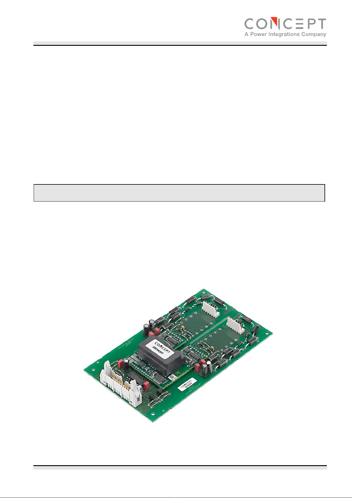
Concept2 2RT0435T Instructions for use

2RT0435T
www.IGBT-Driver.com Page 1
2RT0435T
Target Description & Application Manual
Two layer Base Board exclusively assembled with through-hole components
for 2SC0435T SCALE™-2 driver for 1200V and 1700V IGBT modules or
MOSFETs with an electrical interface for 2-level, 3-level and multilevel
converter topologies with paralleling capability
Abstract
The 2RT0435T is a dual-channel Base Board for CONCEPT’s SCALE™-2 driver core 2SC0435T, a low-cost
SCALE-2 dual-driver core for the reliable driving and safe operation of IGBTs. This Base Board is assembled
only with THT-components using a two-layer PCB.
The Base Board is suitable to drive almost all available dual IGBT modules up to 1700V like 62mm IGBT
modules, 130mm x 140mm IGBT modules and others. The plug-and-play capability (only the gate resistors
are missing) makes it ready to operate immediately after mounting. The user needs invest almost no effort in
designing or adjusting it to a specific application.
Fig. 1 2RT0435T Base Board with driver 2SC0435T

2RT0435T
Target Description and Application Manual
www.IGBT-Driver.com Page 2
Contents
System Overview ...........................................................................................................................3
The Six Steps to Success................................................................................................................4
1. Choose a suitable Base Board/driver ...................................................................................4
2. Connect the Base Board to the IGBT modules......................................................................4
3. Connect the Base Board to the control electronics................................................................4
4. Select the operating mode..................................................................................................4
5. Check the Base Board function ...........................................................................................4
6. Set up and test the power stack .........................................................................................4
Mechanical Dimensions..................................................................................................................6
Assembly Drawing of Gate Resistors.............................................................................................7
Recommended Assembly of Components......................................................................................8
2RT0435T2A0-12...................................................................................................................8
2RT0435T2A0-17...................................................................................................................8
Pin Designation of Connector X1 and X2.......................................................................................9
Description of Interfaces X1 and X2..............................................................................................9
Pin Designation of Connector X3 ...................................................................................................9
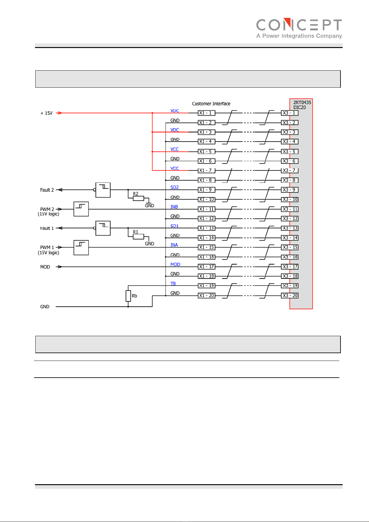
Recommended Interface Circuitry for Connector X3...................................................................10
Description of Interface X3..........................................................................................................10
General ............................................................................................................................... 10
MOD (mode selection) .........................................................................................................11
TB (input for adjusting the blocking time) ............................................................................. 11
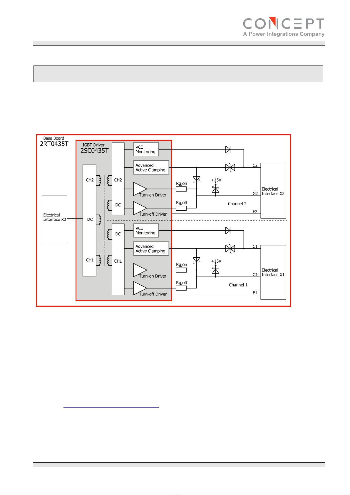
How Do 2RT0435T Base Boards Work in Detail?.........................................................................11
Overview............................................................................................................................. 11
Vce monitoring / short-circuit protection................................................................................. 12
Advanced Active Clamping.................................................................................................... 12
Parallel connection of 2RT0435T........................................................................................... 13
3-level and multilevel topologies ........................................................................................... 13
Low-inductance layout .........................................................................................................13
Bibliography.................................................................................................................................14
The Information Source: SCALE-2 Driver Data Sheets................................................................15
Quite Special: Customized SCALE-2 Drivers ................................................................................15
Technical Support ........................................................................................................................15
Quality..........................................................................................................................................15
Legal Disclaimer...........................................................................................................................15
Ordering Information...................................................................................................................16
Information about Other Products ..............................................................................................16
Manufacturer................................................................................................................................16

2RT0435T
Target Description and Application Manual
www.IGBT-Driver.com Page 3
System Overview
The 2RT0435T are Base Boards for the driver 2SC0435T. 2SC0435T are SCALE-2 driver cores based on the
SCALE-2 technology developed by CONCEPT /1/. This is a set of application-specific integrated circuits (ASICs)
that cover the main range of functions needed to design intelligent gate drivers. The SCALE-2 driver chipset is
a further development of the proven SCALE technology /2/.
The basic topology of the 2RT0435T Base Board is shown in Fig. 2.
Fig. 2 Basic schematic of the 2RT0435T Base Board with 2SC0435T driver
The Base Board contains all necessary components for optimal and safe driving of IGBT modules or MOSFETs:
gate clamping, active-clamping diodes (overvoltage protection at turn-off), Vce monitoring (short-circuit
protection), minimum pulse suppression for both input signals (approx. 400ns for turn-on and approx. 600ns
for turn-off), decoupling of the failure outputs by a MOSFET stage as well as the input electrical connector X3
and both electrical output connectors X1 and X2 to connect the power switches. Moreover, it includes
components for setting the turn-off trip level, the response time and the dead time between both channels in
half-bridge mode. Its plug-and-play capability means that it is ready to operate immediately after mounting.
The user needs invest almost no effort in designing or adjusting the Base Board to a specific application. Only
the gate resistors are not assembled in order to provide full flexibility for the user.
For a detailed description of 2SC0435T, please also refer to “Description & Application Manual for 2SC0435T
drivers” on www.IGBT-Driver.com/go/2SC0435T.

2RT0435T
Target Description and Application Manual
www.IGBT-Driver.com Page 4
The Six Steps to Success
The following steps point out the easy way to use 2RT0435T Base Boards in power converters:
1. Choose a suitable Base Board/driver
When applying 2RT0435T Base Boards, you should note that the gate resistors are not assembled. They must
be assembled according to the used IGBT module before start of operation.
The type designation of the Base Board also includes a number corresponding to the voltage class of the used
power device.
These Base Boards are not valid for IGBT modules of other voltage classes than those specified.
Incorrect use may result in failure.
2. Connect the Base Board to the IGBT modules
Any handling of IGBT modules or drivers is subject to the general
specifications for protecting electrostatic-sensitive devices according to
international standard IEC 60747-1, Chapter IX or European standard
EN 100015 (i.e. the workplace, tools, etc. must comply with these standards).
If these specifications are ignored, both IGBTs and drivers may be damaged.
The Base Board can be easily connected to an IGBT module by using the corresponding connectors X1
(channel 1) and X2 (channel 2).
3. Connect the Base Board to the control electronics
Connect the Base Board plug X3 to your control electronics and supply the Base Board with a voltage of +15V.
4. Select the operating mode
The operating mode can be set with input MOD (interface X3: pin 17). For details, see page 11.
5. Check the Base Board function
Check the gate voltage: For the off-state, the nominal gate voltage is specified in the relevant driver data
sheet /3/. For the on-state, it is +15V. Also check the input current consumption of the Base Board without
clock signals and at the desired switching frequency.
These tests should be performed before installation, as the gate terminals may otherwise not be accessible.
6. Set up and test the power stack
Before starting up the system, it is recommended that each IGBT module be checked separately under power-
cycling conditions. It is usually sufficient to apply the single or double-pulse technique. CONCEPT specially
recommends users to check that the IGBT modules switch inside the SOA in the worst case condition, as this
strongly depends on the specific converter construction.

2RT0435T
Target Description and Application Manual
www.IGBT-Driver.com Page 5
Even if only single IGBTs are tested, all the system’s gate drivers must be supplied with energy.
All the other IGBTs are then kept in the off state by applying negative gate voltages. This is
particularly important when switching the IGBTs under test.
The short-circuit behavior can also be verified at this point.
The system is then ready to start under real-world load conditions. This allows the thermal behavior of the
whole arrangement to be determined.
The system must be re-qualified over the entire specified range of temperature and load conditions.
CAUTION: All handling with high voltages involves risk to life.
It is imperative to comply with the respective safety
regulations!

2RT0435T
Target Description and Application Manual
www.IGBT-Driver.com Page 6
Mechanical Dimensions
Fig. 3 Mechanical dimensions of 2RT0435T with 2SC0435T driver
Information about the primary connection X3:
Electrical connector on the Base Board: 71918-120LF from FCI
Recommended cable connector: 71600-020LF from FCI
Recommended twisted pair flat cable: 1700/20 or 2100/20 from 3MTM

2RT0435T
Target Description and Application Manual
www.IGBT-Driver.com Page 7
Assembly Drawing of Gate Resistors
The turn-on and turn-off gate resistors of 2RT0435T Base Boards are not assembled. They must be assembled
by the user.
Recommended gate resistors are PR03 / 3W / 1% (THT), e.g. from Vishay.
The component positions can be found in Fig. 4:
Fig. 4: Assembly drawing of 2RT0435T with highlighted gate resistors
Turn-on gate resistors for channel 1: R112 and R113 in parallel
Turn-off gate resistors for channel 1: R110 and R111 in parallel
Turn-on gate resistors for channel 2: R212 and R213 in parallel
Turn-off gate resistors for channel 2: R210 and R211 in parallel
Note that the wires of the THT gate resistors should not project more than 1.6mm after soldering (excess
length at bottom side). Furthermore, a minimum distance of 1mm must be maintained between the gate
resistor body and the PCB (see Fig. 5).
Fig. 5: Minimum and maximum distances when soldering THT gate resistors (in mm/mil)

2RT0435T
Target Description and Application Manual
www.IGBT-Driver.com Page 8
Recommended Assembly of Components
Recommended components and component values are given in the bill of material included in the production
documentation of the Base Boards. However, some components which depend on the voltage class of the
power semiconductor used are marked with N.A. in the schematics. See also Fig. 6. They are given below.
Note that gate resistor values are not explicitly given as they depend on the power semiconductor used and on
the application. The gate resistors must be determined and assembled by the user.
2RT0435T2A0-12
The following components marked with N.A. in the schematics and in Fig. 6 are recommended:
D106…D108, D206…D208: 1.5KE220A-E3 (e.g. from Vishay)
D109, D209: 1.5KE250CA-E3 (e.g. from Vishay)
2RT0435T2A0-17
The following components marked with N.A. in the schematics and in Fig. 6 are recommended:
D106…D108, D206…D208: 1.5KE350A-E3 (e.g. from Vishay)
D109, D209: 1.5KE300CA-E3 (e.g. from Vishay)
Fig. 6: Schematic of the secondary side of the Base Board 2RT0435T

2RT0435T
Target Description and Application Manual
www.IGBT-Driver.com Page 9
Pin Designation of Connector X1 and X2
Pin Des. Function
1 Cx Collector of channel x
3 N.C. Not connected
5 N.C. Not connected
7 Ex Emitter of channel x
Pin Des. Function
2 N.C. Not connected
4 N.C. Not connected
6 Gx Gate of channel x
Description of Interfaces X1 and X2
X1 and X2 are the connectors to connect the power switch to the channel 1 (X1) and channel 2 (X2)
respectively. Note that the pin assignments 2-5 must remain free (without crimp contact) in order to guaranty
sufficient creepage path between both channels.
Pin Designation of Connector X3
Pin Des. Function
1 VDC +15V for DC/DC converter
3 VDC +15V for DC/DC converter
5 VCC +15V for primary side electronics
7 VCC +15V for primary side electronics
9 SO2 Status output channel 2
11 INB Signal input channel 2
13 SO1 Status output channel 1
15 INA Signal input channel 1
17 MOD Mode selection (direct/half-bridge)
19 TB Blocking time
Pin Des. Function
2 GND Ground
4 GND Ground
6 GND Ground
8 GND Ground
10 GND Ground
12 GND Ground
14 GND Ground
16 GND Ground
18 GND Ground
20 GND Ground
Fig. 7: Schematic of the primary side of the Base Board 2RT0435T

2RT0435T
Target Description and Application Manual
www.IGBT-Driver.com Page 10
Recommended Interface Circuitry for Connector X3
Fig. 8 Recommended user interface of 2RT0435T
Description of Interface X3
General
The standard DIC20 interface X3 of the Base Board 2RT0435T is very simple and easy to use. It has the
following terminals:
4 x power-supply terminals (but only one 15V power supply is needed)
2 x drive signal inputs
2 x status outputs (fault returns)
1 x mode selection (half-bridge mode/direct mode)
1 x input to set the blocking time
The Base Board is equipped with a 20-pin interface connector. All even-numbered pins are used as GND
connections. The odd-numbered pins are used as inputs or status outputs. It is recommended to use a 20-pin
twisted flat cable. Each input and output signal is then twisted with its own GND wire. All GND pins are
connected together on the 2RT0435T Base Board and should also be connected on the control-board side.
This arrangement produces a very low-inductance connection with high immunity against interferences.

2RT0435T
Target Description and Application Manual
www.IGBT-Driver.com Page 11
All inputs are ESD-protected. Moreover, all digital inputs have Schmitt-trigger characteristics.
MOD (mode selection)
The MOD input allows the operating mode to be selected.
Direct mode
If the MOD input is not connected (floating), or connected to VCC, direct mode is selected.
Half-bridge mode
If the MOD input is low level (connected to GND), half-bridge mode is selected. The dead time is set by a
resistor on the 2RT0435T.
TB (input for adjusting the blocking time)
The terminal TB allows the factory-set blocking time to be reduced by connecting an external resistor to GND
(see Fig. 8). The following equation calculates the necessary resistor Rbconnected between pins TB and GND
in order to define the desired blocking time Tb(typical value):
8.6
][99 ][1507650
][
msTb msTb
kRbwhere 20ms <
T
b
< 90ms
The blocking time can also be set to a minimum of 9µs by selecting Rb= 0Ω.
If not used, the input TB can be left open.
How Do 2RT0435T Base Boards Work in Detail?
Overview
All drivers of the SCALE-2 driver family with an electrical interface are equipped with usual protection functions
such as Vce monitoring for short-circuit protection, operation inhibit after fault, supply-undervoltage shutdown
and status feedback.
Outstanding features of 2RT0435T Base Boards are: compact size, simple mounting - directly to the IGBT
module over the interfaces X1/X2, Advanced Active Clamping function, minimum pulse suppression of input
signals, decoupling of failure outputs by MOSFET stage. Active clamping describes an active scheme designed
to protect the IGBTs against overvoltage during turn-off. It is particularly relevant when turning an IGBT off in
cases of high DC-link voltage and collector current or short circuit. The 2RT0435T Base Boards also allow
parallel operation of IGBT modules in order to increase the system power (see “Parallel connection of
2RT0435T” on page 13).

2RT0435T
Target Description and Application Manual
www.IGBT-Driver.com Page 12
Vce monitoring / short-circuit protection
The basic Vce monitoring circuit implemented in
2RT0435T SCALE-2 Base Boards is illustrated in
Fig. 2. Both IGBT collector-emitter voltages are
measured with sense diodes. Vce is checked after
the response time (see Fig. 9) at turn-on to
detect a short circuit. If this voltage is higher than
the programmed threshold Vth, the driver detects
a short circuit at the IGBT and signals it
immediately to the corresponding SOx output.
The corresponding IGBT is immediately switched
off. The IGBT is kept off (non-conducting) and
the fault is shown at pin SOx as long as the
blocking time is active.
The blocking time is applied independently to
each channel. It starts when Vce exceeds the
threshold of the Vce monitoring circuit.
Note: The desaturation function is for short-
circuit detection only and cannot provide
overcurrent protection. However, overcurrent
detection has a lower time priority and can be
easily provided by the application.
Advanced Active Clamping
Active clamping is a technique designed to partially turn on the IGBT in case the collector-emitter voltage
exceeds a predefined threshold. The IGBT is then kept in linear operation. The basic circuit for active clamping
can be found in /5/.
Basic active clamping topologies implement a single feedback path from the IGBT’s collector through transient
voltage suppressor devices (TVS) to the IGBT gate. The 2RT0435T Base Boards support CONCEPT’s Advanced
Active Clamping based on this principle: when active clamping is activated, the turn-off MOSFET of the driver
is switched off in order to improve the effectiveness of the active clamping and to reduce the losses in the
TVS. This feature is mainly integrated in the secondary-side ASIC.
Fig. 9 Turn-on characteristic of an IGBT

2RT0435T
Target Description and Application Manual
www.IGBT-Driver.com Page 13
Fig. 10 Test circuit (left) and typical switching behavior (right)
Legend to Fig. 10
t0 = Initiation of the turn-off process
t1 = Start of turn-off time
t2 = Start of collector current fall time
t3 = Maximum collector voltage
t4 = IGBT is blocking, start of tail current
t5 = End of tail current
In comparison with other driving methods, active clamping allows enhanced utilization of the IGBT modules
during normal operation by increasing the switching speed and therefore reducing switching losses. The
overvoltage at fault-current turn-off is also managed by active clamping. For the maximum permitted DC-link
voltage, refer to the Base Board data sheets /4/.
Parallel connection of 2RT0435T
If parallel connection of 2RT0435T Base Boards is required, please refer to the application note AN-0904 /7/
on www.IGBT-Driver.com/go/app-note and to /6/.
3-level and multilevel topologies
If the 2RT0435T Base Boards are to be used in 3-level or multilevel topologies, please refer to the application
note AN-0901 /8/ on www.IGBT-Driver.com/go/app-note.
Low-inductance layout
The active-clamping function should not lead anyone to forget about the inductances of the power stack. For
several reasons, it is recommended to reduce the DC-link stray inductance to about 30nH…100nH depending
on the IGBT modules used with 2RT0435T Base Boards.

2RT0435T
Target Description and Application Manual
www.IGBT-Driver.com Page 14
Bibliography
/1/ “Smart Power Chip Tuning”, Bodo’s Power Systems, May 2007
/2/ “Description and Application Manual for SCALE Drivers”, CONCEPT
/3/ Data sheets SCALE-2 driver core 2SC0435T, CONCEPT
/4/ Data sheets Base Board 2RT0435T, CONCEPT
/5/ “Advantages of Advanced Active Clamping”, Power Electronics Europe, November/December 2009
/6/ “Intelligent Paralleling”, Bodo’s Power Systems, March 2009
/7/ Application note AN-0904: Direct Paralleling of SCALE-2 Gate Driver Cores, CONCEPT
/8/ Application note AN-0901: Methodology for Controlling Multi-Level Converter Topologies with SCALE-2
IGBT Drivers, CONCEPT
Note: These documents are available on the Internet at www.IGBT-Driver.com

2RT0435T
Target Description and Application Manual
www.IGBT-Driver.com Page 15
The Information Source: SCALE-2 Driver Data Sheets
CONCEPT offers the widest selection of gate drivers for power MOSFETs and IGBTs for almost any application
needs. The largest website on gate-drive circuitry anywhere contains all data sheets, application notes and
manuals, technical information and support sections: www.IGBT-Driver.com
Quite Special: Customized SCALE-2 Drivers
If you need an IGBT driver that is not included in the delivery range, please don’t hesitate to contact CONCEPT
or your CONCEPT sales partner.
CONCEPT has more than 25 years experience in the development and manufacture of intelligent gate drivers
for power MOSFETs and IGBTs and has already implemented a large number of customized solutions.
Technical Support
CONCEPT provides expert help with your questions and problems:
www.IGBT-Driver.com/go/support
Quality
The obligation to high quality is one of the central features laid down in the mission statement of CT-Concept
Technologie GmbH. The quality management system covers all stages of product development and production
up to delivery. The drivers of the SCALE-2 series are manufactured to the ISO9001:2000 quality standard.
Legal Disclaimer
The statements, technical information and recommendations contained herein are believed to be accurate as
of the date hereof. All parameters, numbers, values and other technical data included in the technical
information were calculated and determined to our best knowledge in accordance with the relevant technical
norms (if any). They may base on assumptions or operational conditions that do not necessarily apply in
general. We exclude any representation or warranty, express or implied, in relation to the accuracy or
completeness of the statements, technical information and recommendations contained herein.
No responsibility is accepted for the accuracy or sufficiency of any of the statements, technical information,
recommendations or opinions communicated and any liability for any direct, indirect or consequential loss or
damage suffered by any person arising therefrom is expressly disclaimed.

2RT0435T
Target Description and Application Manual
www.IGBT-Driver.com Page 16
Ordering Information
Note that the Base Boards 2RT0435T2A0-xx cannot be ordered. This Base Board is a reference design for the
production by the customer. We recommend a board-thickness of 1.55mm. All necessary production data (like
CAM files and BOM) are published at the product homepage: www.IGBT-Driver.com/go/2RT0435T
Refer to www.IGBT-Driver.com/go/nomenclature for information on driver nomenclature.
Information about Other Products
For drivers adapted to high-voltage or high-power IGBT modules
Direct link: www.IGBT-Driver.com/go/plug-and-play
For other drivers, evaluation systems product documentation and application support
Please click onto: www.IGBT-Driver.com
Manufacturer
CT-Concept Technologie GmbH
A Power Integrations Company
Johann-Renfer-Strasse 15
2504 Biel-Bienne
Switzerland
Phone +41 - 32 - 344 47 47
Fax +41 - 32 - 344 47 40
E-mail [email protected]
Internet www.IGBT-Driver.com
2014 CT-Concept Technologie GmbH - Switzerland. All rights reserved.
We reserve the right to make any technical modifications without prior notice. Version 1.0 from 2014-04-10
Table of contents