Condor 260 BAIT User manual

Installation and
Operation Manual

2
Introduction
Thank you for choosing our Fish Finder and welcome to the innovations of Condor
Marine!
Your Fishfinder is a high-quality sonar designed for both professional and novice
fisherman with trouble-free use in a variety of water areas. To familiarize yourself
better with the product’s operation and maximize the utilization, we invite you to
read the User’s Manual carefully.
Carefully read the installation steps and properly mounting the transducer and
sonar unit which will pay off in optimum performance of your Fishfinder.
An improper installation, especially the improper transducer installation may cause
your sonar unit working abnormally or not working at all.
For any possible problems you may encounter during the operation, please switch
to the Trouble shooting section for reference.
All right reserved! Except as expressly provided herein, no part of this manual may
be copied, reproduced, republished, transmitted or distributed for any purpose,
without prior written consent of Condor Marine.
Condor Marine may find it necessary to change or end our policies, regulations,
and special offers at any time. We reserve the right to change or improve our
products and to make changes in the content without obligation to notify any
person or organization.
Note: Our company holds the right to update the products, and it is not obligated
for our company to update the former products according the new standard.

3
Index
Introduction ...........................................................................................................2
Installation .............................................................................................................4
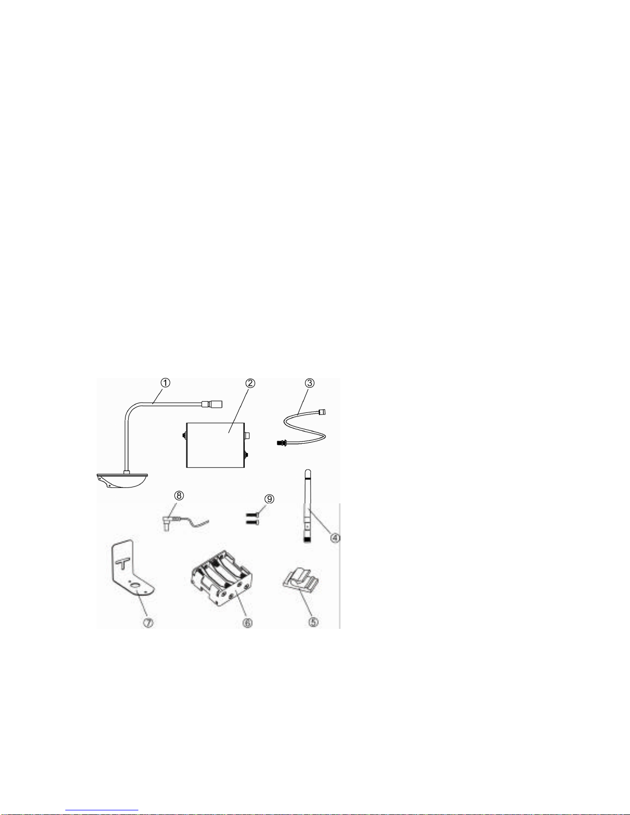
Packing list ............................................................................................................4
Using the product ..................................................................................................5
Powering ...............................................................................................................6
Sonar unit installation ............................................................................................7
Install the RES sensor to bait boat ........................................................................8
Tool list ..................................................................................................................9
Introduction of RES sensor ...................................................................................9
RES sensor installation method –1.....................................................................10
RES sensor installation method –2.....................................................................17
Operation .............................................................................................................21
Understanding sonar ............................................................................................21
Keyboard instruction ............................................................................................22
1. Sonar ................................................................................................................23
Sensitive ..............................................................................................................23
Noise Filter ..........................................................................................................23
Magic Grayline .....................................................................................................24
Fish ID. Sens .......................................................................................................25
2. Display .............................................................................................................26
Depth Range ........................................................................................................26
Zoom Range ........................................................................................................27
Backlight ..............................................................................................................28
Contrast ...............................................................................................................28
Overlap Data .......................................................................................................28
3. Alarm ...............................................................................................................29
Depth Alarm .........................................................................................................29
Fish Alarm ............................................................................................................30
Main Battery .........................................................................................................30
Boat Battery .........................................................................................................31
4. System .............................................................................................................31
Beeper ……..........................................................................................................31
Units .....................................................................................................................32
Language .............................................................................................................32
System Reset ......................................................................................................33
Simulator .............................................................................................................33
Trouble Shooting .................................................................................................34
Specifications and Features ................................................................................37

4
Installation
Do not begin the installation unless you have read the manual instruction carefully,
which contains information critical to the correct installation of your Fishfinder.
Packing list
Before you install the transducer to your bait boat, please check the packing list
below, and make sure you are not missing any items.
The packing list of Condor 260 Bait includes 2 parts as shown following:
1. RES Sensor
The electric control & sonar system enclosed by the dashed line are named RES
sensor.
1) A wireless remote sonar sensor
2) Acontrolling box
3) Anantenna-extended-cable
4) Twoantennasfor mounting on
bait boat & sonar display
5) Two cable clip
6) A battery holder
7) A metal bracket to fix the
sensor
8) A power cable
9) Two screws

5
2. Sonar Unit
Sonar control head
Toothed connector-R
Toothed connector-L
Locking bolt
Power Cable
Plastic base
A copy of manual are also included:
Note: the above sonar units has been assembled in the gift box before shipment
Using the product
Condor 260 Bait is specially designed to be used with bait boat. Properly install
the RES sensor to your bait boat, powering the unit, and put the assembled bait
boat & RES sensor into the water, and then you are ready to know the bottom
condition in 300m water area.
Following is an instruction picture of 2 ways to install the RES sensor to your bait
boat:

6
Note: to get the best sonar performance, we suggest adopting the way-B
Powering
There are 2 ways to power the Condor 260 Bait:
1) Use 8 x AA battery
Please assemble the batteries according to the instruction figure curved on the
plastic housing.
A
B

7
Instruction figure of battery installation
2) Use your bait boat battery
Sometimes, you may prefer using a battery for power supplying.
In the package, you can find a separate power cable, which is used to connect the
sonar unit to your bait boat battery.
Connect to a battery
Power Cable

8
Note: in the power cable, there are 2 internal wires:
-The red one is for positive electrode.
-The black one is for negative electrode.
Note: Condor 260 Bait can be powered by almost all kinds of battery with voltage
of 6~18v
Warning:when use the boat battery for power supplying; we are
not
responsible for over-voltage or over-current failures.
To prevent such possible failures happening, we
suggest
you using a 3Amp
fuse.
Install the RES sensor to your bait boat
The picture below is an overall installation instruction showing you the general
conception to install the RTS sensor to the bait boat, which is just for
your
reference.

9
Note: the selected bait boat here is just for your reference, the installation way
may vary according to the structure of different bait boats.
Tool List (not included)
1) Hand drill
2) 5/32” drill bits
3) Phillips and flat-head screwdriver
4) Marine sealant
Introduction of the RES sensor
RES sensor indicates the whole set of electric & sonar control system. It is used to
be mounted on your bait boat.
1) A wireless remote sonar
sensor
2) Acontrolling box
3) Anantenna-extended-cable
4) Twoantennasfor mounting
on bait boat & sonar display
5) Two cable clip
6) A battery holder
7) A metal bracket to fix the
sensor
8) A power cable
9) Two screws
Note: the
antenna-extended
cable is used to connect
the
antenna and the
control box. As sometimes you may have to mount the antenna on your bait
boat, instead of connect it directly to the control box. Thus it will be convenient for
you to find enough space to place the control box at a proper position.

10
RES sensor installation method -1
1. Make a supporting plate to hold the wireless sensor.
The shape of supporting plate may be different according to the shape of your bait
boat.
Note: we provide asimple metal bracket (see packing list), which could help
you making a simple sensor installation on some bait boats.
Metal bracket
Hull of boat

11
2. Find a proper position and drill two holes on the top cover of your bait boat, as
figured below:
The hole-1is used to be through the sensor cable, the diameter should be about
11.5mm. The hole-2 is used to mount the antenna; the diameter should be about
5.8mm
3. Mount the antenna on the top cover of your bait boat.
a) Mount the antenna-extended cable to the top cover
There are two connector of the antenna-extended cable, one is used to connect to
the antenna, and another is used to connect to the control box.
Connect to controlling boxConnect to antenna

12
Firstly, take out the screw from the antenna-extended cable, and then hold one
end of the cable through the hull of bait boat (as instructed below). Finally, tighten
the screw.
b) Screwthe antennatothe
antenna-extended
cable.

13
4. Mount the wireless sensor on the supporting plate, as instructed below
a) Drill three holes on the supporting
plate.
-Diameter of hole-1 is about 12.5mm
-Diameter of hole-2 and hole-3 is
about 3.5mm
b) Tighten the senser by screws
Note: use a pencil to mark the
position before drilling the hole-2 and
hole-3.
5. Mount supporting plate on the top cover of bait boat.
Drill 4 holes on the supporting plate, and tighten the supporting plate on the top
cover of your bait boat by screws.

14
6. Find a proper position and place the control box into the bottom cover of your
bait boat.
Note: It could be better to find a way to fix the control box in the bottom cover of
your bait boat. As when used with your bait boat in the water, the control box may
wobble with the shave, which may damage the inner electronic parts.
7. Connect the antenna-extended cable to the control box.
8. Connect the wireless sensor to the control box.

15
9. Connect the control box to the battery.
There are 2 ways to power the control box
a) Connect to a 9v alkaline battery
In the package you can find a battery buckle, which is used to connect the cable to
a 9v alkaline battery.
b) Connect to the bait boat battery
In most circumstances, you can choose connecting the cable to your bait boat
battery.
Connect to the battery

16
Note: correctly connect the control box to the bait boat battery, and then you can
monitor the remained voltage of your bait boat all the time. Avoiding using under a
low battery.
Note: the range of battery monitoring is 5.2~15v.
Warning:be careful not reversing connection of positive & negative pole to the
bait boat battery. (Black wire is for negative pole; black & white wire is for positive
pole).
10. Assemble the bait boat.
With the above steps were finished, carefully assemble your bait boat, then the
complete set of bait boat & wireless fish finder is ready to use.
Note: sometimes you may need a switch to control on/off of the RES sensor (see
the “packing list”).
1) Drill a hole on your bait boat housing; tighten the switch on the bait boat.
2) Connect the switch to the power cable.
3) Spread some sealed glue to the drilled location, preventing water leakage from
happening.

17
RES sensor installation method -2
As the structure of bait boats is different, sometimes maybe you prefer mounting
the sensor to your bait boat in other method, see the following example:
Note: for such installation method, finding a proper mounting location for the
sensor is very important. Otherwise an improper mounting position may cause a
short Remote Control distance or abnormal display on the screen

18
Sonar working method
When sonar works, the signals are remitted in the direction as instructed below:
So, in the area Aand area B, there should be no any obstacle, otherwise the sonar
signals will be “blocked”, thus sonar unit will not be able to receive the signal
normally, which will cause short Remote Control distance, or abnormal display on
the screen.
For example, in the following sensor mounting figure,
Ais right;Bis wrong;
-In the A mounting position, the sonar signals can be remitted without any
obstacle in the two direction;
-In the Bmounting position, the sonar signals cannot be remitted normally, as
they are blocked by the hull of the bait boat;

19
1. Find a proper mounting position, and drill 3 holes on the bottom of your bait boat
3 holes
Note: the 3 holes should be drilled with the following dimension
2. Hold the sensor cable through the 12mm-hole

20
3. Fix the sensor with 2 screws
Note: please spread some sealed glue on the screws before fixing the sensor.
4. Spread some sealed glue to the drilled location, preventing water leakage from
happening.
5. Carry out the following steps same with step 6~10 instructed in “RES sensor
installation method –1”
Table of contents
Other Condor Fish Finder manuals
Popular Fish Finder manuals by other brands

Humminbird
Humminbird Matrix 65 Operation manual

Humminbird
Humminbird 788c Operation manual

Garmin
Garmin GWS 10 Marine Wind Sensor Important safety information

Humminbird
Humminbird 777c2 Operation manual

Marcum Technologies
Marcum Technologies Showdown Troller user manual

Humminbird
Humminbird RF10 SmartCast Operation manual

Hawkeye Mfg
Hawkeye Mfg F33P Installation and operation manual

Humminbird
Humminbird NMEA 2000 module Installation and operation manual

oneConcept
oneConcept KT-Fisher manual

Standard Horizon
Standard Horizon CPF390i owner's manual

Simrad
Simrad SX90 - DATASHEET FOR NAVAL AND COAST GUARD REV... Operator's manual

Humminbird
Humminbird TCR 101 Operation manual