CONFORAMA SABA HD600BOX-60 User manual

CONFORAMA France SA
80 Boulevard du Mandinet
LOGNES
77432 Marne laVallée Cedex 2
FRANCE
HD600BOX-60
FR
GB

TABLE DES MATIERES
Recommandations et suggestions � � � � � � � � � � � � � � � � � � � � � � � � � � 2
Installation � � � � � � � � � � � � � � � � � � � � � � � � � � � � � � � � � � � � � � � � 4
Utilisation � � � � � � � � � � � � � � � � � � � � � � � � � � � � � � � � � � � � � � � � 5
Entretien � � � � � � � � � � � � � � � � � � � � � � � � � � � � � � � � � � � � � � � � � 6
Spécications techniques � � � � � � � � � � � � � � � � � � � � � � � � � � � � � � � 7
Composants � � � � � � � � � � � � � � � � � � � � � � � � � � � � � � � � � � � � � � � 9
Dimensions� � � � � � � � � � � � � � � � � � � � � � � � � � � � � � � � � � � � � � � 10
Installation � � � � � � � � � � � � � � � � � � � � � � � � � � � � � � � � � � � � � � � 11
Branchements � � � � � � � � � � � � � � � � � � � � � � � � � � � � � � � � � � � � � 14
Utilisation � � � � � � � � � � � � � � � � � � � � � � � � � � � � � � � � � � � � � � � 15
Entretien � � � � � � � � � � � � � � � � � � � � � � � � � � � � � � � � � � � � � � � � 16
Éclairage � � � � � � � � � � � � � � � � � � � � � � � � � � � � � � � � � � � � � � � � 17
Enlèvement des appareils ménagers usagés� � � � � � � � � � � � � � � � � � � � 18
Nous vous remercions d’avoir choisi la qualité SABA� Ce produit a été créé par
notre équipe de professionnels et selon la réglementation européenne� Pour
une meilleure utilisation de votre nouvel appareil, nous vous recommandons
de lire attentivement ce manuel d’instructions et de le conserver pour toute
référence ultérieure� FR

Recommandations et suggestions
• Le mode d’emploi s’applique à plusieurs versions de cet
appareil� Par conséquent, vous pourrez trouver des descriptions
de fonctionnalités individuelles qui ne s’appliquent pas à votre
appareil spécique�
• Cet appareil est destiné à être utilisé dans des applications
domestiques et analogues telles que :
– des coins cuisines réservés au personnel dans des magasins,
bureaux et autres environnements professionnels ;
– des fermes ;
– l’utilisation par les clients des hôtels, motels et autres
environnements à caractère résidentiel;
– des environnements du type chambres d’hôtes�
• Une ventilation convenable de la pièce doit être prévue
lorsqu’une hotte de cuisine est utilisée simultanément avec
des appareils utilisant du gaz ou un autre combustible�
• Il y a risque d’incendie si le nettoyage n’est pas eectué
conformément aux instructions�
• Ne pas amber d’aliments sous la hotte de cuisine�
• ATTENTION : Les parties accessibles de cet appareil peuvent
devenir chaudes lorsqu’il est utilisé avec des appareils de
cuisson�
• Cet appareil peut être utilisé par des enfants âgés d’au moins
8 ans et par des personnes ayant des capacités physiques,
sensorielles ou mentales réduites ou dénuées d’expérience ou
de connaissance, s’ils (si elles) sont correctement surveillé(e)
s ou si des instructions relatives à l’utilisation de l’appareil en
toute sécurité leur ont été données et si les risques encourus
ont été appréhendés� Les enfants ne doivent pas jouer avec
l’appareil� Le nettoyage et l’entretien par l’usager ne doivent
pas être eectués par des enfants sans surveillance�
• Si le câble d’alimentation est endommagé, il doit être
remplacé par le fabricant, son service après-vente ou des
personnes de qualication similaire an d’éviter un danger�
• L’air ne doit pas être envoyé dans un conduit utilisé pour
évacuer les fumées d’appareils utilisant du gaz ou un autre
combustible (ne s’applique pas aux appareils qui renvoient
uniquement l’air dans la pièce);
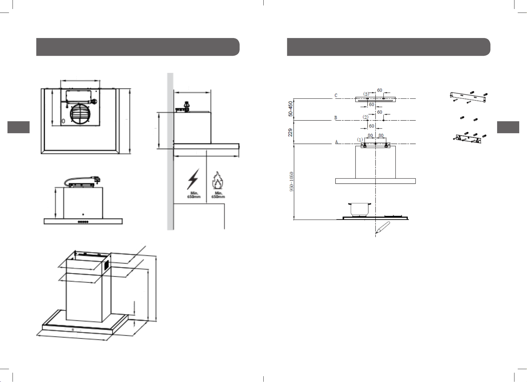
• La distance minimale à respecter entre la surface support des
récipients de cuisson de la table de cuisson et la partie la plus
basse de la hotte de cuisine� (Lorsque la hotte de cuisine est
placée au-dessus d’un appareil à gaz, cette distance doit être
d’au moins 65 cm)
• Les réglementations concernant l’évacuation de l’air doivent
être respectées�
• En ce qui concerne les instructions d’installation de l’appareil
et les raccordements électriques, référez-vous au paragraphe
ci-après de la notice�
• En ce qui concerne les instructions de nettoyage de l’appareil,
référez-vous au paragraphe ci-après de la notice�
32
FR FR

Installation de reux des gaz d’échappement� La cuisine doit avoir une
ouverture communiquant directement avec l’air libre an de
garantir l’entrée d’air pur�
• Si la hotte est utilisée avec des appareils alimentés par une
énergie autre que l’électricité, la pression négative dans la
pièce ne doit pas dépasser 0,04 mbar an d’éviter que les
fumées ne puissent être aspirées dans la pièce par la hotte�
• Les réglementations concernant le rejet de l’air doivent être
respectées�
• Le fabricant ne saurait être tenu
responsable des dommages résultant
d’une installation incorrecte ou
défectueuse�
• Respecter la distance minimale entre la
surface portant les ustensiles de cuisine
et la partie la plus basse de la hotte� (Si la hotte est installée au-
dessus d’une cuisinière à gaz, cette distance doit être d’au moins
650mm� Si le mode d’emploi de la cuisinière à gaz spécie une
plus grande distance, celle-ci prévaudra� Cette distance de
650 mm peut être réduite pour : les parties non combustibles
des hottes et les pièces fonctionnant à très basse tension de
sécurité, à condition que ces pièces ne donnent pas accès à
d’autres pièces sous tension si elles venaient à être déformées)
• Vériez que la tension du secteur correspond à celle indiquée
sur la plaque signalétique xée à la hotte�
• Pour les appareils de classe I, vériez que l’alimentation de la
prise de courant garantit une mise à la terre adéquate�
• Raccordez l’extracteur à la cheminée d’évacuation par un tuyau
d’au moins 120 mm de diamètre� La longueur totale de la
cheminée doit être la plus courte possible�
• Si l’extracteur est utilisé en combinaison avec des appareils
non électriques (appareils à gaz etc�), il convient d’assurer un
degré d’aération susant dans la pièce an d’éviter tout risque
Utilisation
• Ne laissez en aucun cas de grandes
ammes nues brûler sous la hotte
lorsqu’elle est en marche�
• Réglez l’intensité des ammes de
manière à les diriger uniquement
vers le fond de la casserole, sans les
laisser déborder sur les côtés�
• Les friteuses doivent rester sous surveillance constante
pendant qu’elles fonctionnent : l’huile surchauée est
susceptible de s’enammer�
• Ne faites pas amber des aliments sous la hotte : risque
d’incendie�
• ATTENTION : Les pièces accessibles peuvent être portées à très
haute température en cas d’utilisation avec des appareils de
cuisson»
54
FR FR

Entretien
• Éteignez et débranchez
l’appareil avant toute
manipulation d’entretien�
• Nettoyez et/ou remplacez les
ltres à la fréquence spéciée
(risque d’incendie)�
• Nettoyez la hotte avec un chion imbibé de détergent liquide
neutre�
• L’appareil est conçu pour un maximum de 4 plaques de
cuisson�
Le symbole sur l’emballage indique que ce produit ne doit
pas être jeté avec les ordures ménagères� Il doit être apporté
à un centre de récupération et de recyclage des équipements
électriques et électroniques� En mettant au rebut ce produit de
manière responsable, vous aiderez à prévenir les conséquences
potentiellement négatives pour l’environnement et la santé
humaine, résultant d’une élimination incorrecte de ce produit�
Pour plus de détails concernant le recyclage de ce produit,
veuillez contacter les administrations locales, le service de
ramassage des poubelles de votre commune ou le magasin
d’achat�
Spécifications techniques
Marque SABA
Modèle HD600BOX-60
Consommation énergétique
annuelle (AEC)
91 kWh/an
Classe d’ecacité énergétique C
Ecacité uidodynamique
(FDE)
19�6
Classe d’ecacité
uidodynamique
C
Ecacité lumineuse (LE) 54 lux/watt
Classe d’ecacité lumineuse A
Ecacité de ltration de
graisses (GFE)
75�5
Classe d’ecacité de ltration
de graisses
C
Débit d’air maximal (Q max) 640 m3/h
Niveau de puissance
acoustique (LWA)
67 dB
Puissance nominale 218W
(Moteur : 1 x 215W, Lampe :
2 x 1�5W max�)
76
FR FR

Tension et fréquence
nominales
220-240V ~ 50 Hz
Moteur 230V 50 Hz ~ 215W
Lampe 2 x 12V 50 Hz –1�5 W max�
- type G4
Diamètre de l’ouverture 150 mm
Dimensions du produit
(L x l x P)
440 mm x 600 mm x 500 mm
Le tableau ci-dessus présente les informations relatives à votre
hotte� Les résultats d’essai sont obtenus dans le respect des
exigences no 65/2014 et 66/2014 de l’UE�
Dans certaines circonstances, un appareil électrique peut
entraîner un danger�
Composants
Réf� Qté Eléments du produit
1 1 Corps de la hotte, incluant
: Boutons, éclairage,
ventilateur, ltre�
2�1 1 Cheminée décorative
inférieure
2�2 1 Cheminée décorative
supérieure
3 1 Bride (en option)
4 1 Tuyau d'évacuation
(L : 1�5m)
5 2 Filtre à charbon actif
(en option)
Réf� Qté Accessoires de xation
10 7 Vis 5 x 50
11 7 Chevilles murales
12 6 Vis 4,2 x 9,5
20 1 Support d’accrochage de
la hotte
21 2 Support de xation de la
cheminée
Qté Documentation
1 Notice d’utilisation 98
FR FR
2�2
2�1 3
4
1
5
20
21
12
11
10

Dimensions
unité : mm
Installation
PERÇAGE DESTROUS ET FIXATION DU SUPPORT
La première étape consiste à tracer les lignes suivantes :
• Tracer au centre de la zone où la hotte va être installée une
ligne de symétrie verticale allant jusqu’à la hauteur max du
tuyau d’évacuation�
• Une ligne horizontale A 950 - 1050 mm au-dessus de la
cuisinière�
• Une ligne horizontale B 229 mm au-dessus de la ligne
horizontale A�
300
286
500
286
280
500
240
304
306
601
287
289
40
540
575-1010
500
1110
FR FR
Ligne de symétrie verticale

• Une ligne horizontale C 50-450 mm au-dessus de la ligne
horizontale B� Cétant en fonction de la hauteur de sortie
d’aération où le tuyau d’évacuation est raccordé�
Marquez les points suivants en veillant à l’alignement
horizontal :
• Marquez 3 points (1) sur la ligne horizontale A, à 80 mm aux 2
côtés, le point central étant sur la ligne de symétrie verticale�
(Vous pouvez aussi utiliser le support 20 pour marquer les
repères)
• Marquez 2 points (2) sur la ligne horizontale B, à 60 mm des 2
côtés de la ligne verticale�
• Marquez 2 points (3) sur la ligne horizontale C, à 60 mm des 2
côtés de la ligne verticale�
Fixez les supports :
• Percez des trous aux emplacements marqués avec un foret de
10 mm�
Par mesure de précaution, il est conseillé de ne percer les trous
aux points (2) sur la ligne B qu’une fois la cheminée inférieure
avec son support 21 sera assemblée sur la hotte� (Voir Fig�2)�
Ceci permettra de vérier si les trous du support sont bien en face
avec les points (2) et éventuellement de marquer de nouveaux
points de manière précise à partir du support installé�
• Insérez les chevilles murales 11 dans les trous�
• Fixez le support de xation de la hotte 20 sur la ligne
horizontale Aavec 3 vis 10 (5 x 50)�
• Fixez le support de xation de la cheminée 21 sur la ligne
horizontale Cavec 2 vis 10 (5 x 50)�
Cheminée décorative inférieure (Fig.1)
• Raccordez le tuyau d’évacuation�
• Assemblez la cheminée inférieure sur la hotte avec 2 vis 12
(4�2x9�5) fournies�
• Fixez le support de xation 21 sur la cheminée avec 2 vis 12�
Accrochez la hotte (Fig.2) :
• Accrochez la hotte au support de xation 20 et veillez à son
alignement horizontal�
• Vériez si les trous du support 21 soient bien en face des
points (2) sur la ligne B, sinon marquez de nouveaux repères
directement à partir du support�
• Enlevez la hotte, percez les trous et insérez les chevilles�
• Réinstallez la hotte et xez avec 2 vis 10 (5 x 50) sur support 21�
Figure 1
Figure 2 1312
FR FR

Branchements
Tuyau d’évacuation
Lors de l’installation de la version
au système à évacuation, raccordez
la hotte à la cheminée à l’aide d’un
tuyau exible ou rigide de 150 ou
120 mm, le choix étant laissé à
l’installateur�
• Si vous souhaitez installer une connexion d’évacuation de 120
mm, installez la bride 3à la sortie du corps de la hotte�
• Fixez le tuyau 4avec des colliers de serrage (non fournis)�
• Enlevez les éventuels ltres à charbon�
Cheminée Décorative Supérieure
• Insérez la cheminée décorative supérieure 2�2 dans la
cheminée inférieure 2�1 et faites-la coulisser jusqu’au support
de xation de la cheminée 21 sur la ligne C�
• Fixez la cheminée supérieure 2�2 au support 21 avec 2 vis 12
(4�2x9�5) fournies�
Utilisation
Réglage de vitesse.
Une fois la hotte allumée, un bip sonore retentit et toutes les
touches s’illuminent pendant 1 s, indiquant que la hotte est en
marche� La hotte étant allumée :
• Bouton marche/arrêt : Allume / éteint l’appareil� En état
de marche, un 1er appui met l’appareil en arrêt diéré dans 3
minutes, un 2nd appui le met en arrêt immédiat�
• Touche lumière : Allume / éteint la lampe indépendamment
des autres touches�
• Touche Plus (+) : Augmente la vitesse d‘un cran� Un bip
retentit quand le réglage est au Max�
• Touche Moins (-) : Diminue la vitesse d‘un cran� Un bip
retentit quand le réglage est au Min�
Lampe Moins Écran Plus Marche/Arrêt
1514
FR FR

FILTRES À GRAISSE
NETTOYAGE DES FILTRES À GRAISSE MÉTALLIQUES AUTOPORTANTS
• Les ltres doivent être nettoyés tous les 2 mois, ou plus
fréquemment en cas d’utilisation particulièrement intensive ;
ils peuvent être nettoyés au lave-vaisselle�
• Enlevez les ltres un par un en les poussant vers l’arrière de la
hotte et en les tirant simultanément vers le bas�
• Évitez de déformer les parties des ltres pendant le lavage�
Avant de les remonter sur la hotte, assurez-vous qu’ils sont
complètement secs� (La couleur de la surface du ltre peut
changer avec le temps mais cela n’a aucune incidence sur
l’ecacité du ltre)�
• Lors de la réinstallation de ltres, faites attention au sens de
montage : la poignée est orientée vers l’extérieur�
FILTRE À CHARBON ACTIF (VERSION À RECYCLAGE)
Ces ltres ne sont pas lavables et ne peuvent pas être régénérés�
Ils doivent être remplacés tous les 4 mois environ ou plus
fréquemment en cas d’utilisation intensive�
REMPLACEMENT DU FILTRE À CHARBON ACTIF
• Démontez les ltres à graisse métalliques�
• Retirez le ltre à charbon actif saturé�
• Insérez les ltres neufs�
• Remettez en place les ltres à graisse métalliques�
DÉMONTER REMONTER
DÉMONTERREMONTER
Éclairage
REMPLACEMENT DE LA LAMPE
Les ampoules sont à LED de longue durée de vie et haut
rendement énergétique� Il n’est donc normalement pas
nécessaire de les remplacer pendant la durée de vie du produit�
Dans l’éventualité peu probable qu’elles tombent en panne, elles
doivent être remplacées par un technicien qualié�
Puissance
maximale
Tension Photo Culot Code
ILCOS D
Circulaire/
diamètre :
70mm
1,5W DC 12V —— DSR-
1�5-S-70
Entretien
1716
FR FR

Enlèvement des appareils ménagers usagés
La directive européenne 2012/19/EU sur les Déchets des
Equipements Electriques et Electroniques (DEEE), exige que
les appareils ménagers usages ne soient pas jetés dans le
ux normal des déchets municipaux� Les appareils usagés
doivent être collectés séparément an d’optimiser le taux de
récupération et le recyclage des matériaux qui les composent,
etréduire l’impact sur la santé humaine et l’environnement�
Le symbole de la poubelle barrée est apposé sur tous les produits
pour rappeler les obligations de collecte séparée�
Les consommateurs devront contacter les autorités locales ou leur
revendeur concernant la démarche à suivre pour l’enlèvement de
leur vieil appareil�
18
FR

TABLE OF CONTENTS
Thank you for choosing SABA quality�This product has been developed by our
team of professional and according to European regulations� In order to get the
most out of your new appliance, we recommend that you read this instruction
manual carefully and keep it for future reference�
Recommendations and suggestions � � � � � � � � � � � � � � � � � � � � � � � � 20
Installation � � � � � � � � � � � � � � � � � � � � � � � � � � � � � � � � � � � � � � � 22
Use � � � � � � � � � � � � � � � � � � � � � � � � � � � � � � � � � � � � � � � � � � � 23
Maintenance � � � � � � � � � � � � � � � � � � � � � � � � � � � � � � � � � � � � � � 24
Technical information� � � � � � � � � � � � � � � � � � � � � � � � � � � � � � � � � 25
Components � � � � � � � � � � � � � � � � � � � � � � � � � � � � � � � � � � � � � � 27
Dimensions� � � � � � � � � � � � � � � � � � � � � � � � � � � � � � � � � � � � � � � 28
Installation � � � � � � � � � � � � � � � � � � � � � � � � � � � � � � � � � � � � � � � 29
Connections � � � � � � � � � � � � � � � � � � � � � � � � � � � � � � � � � � � � � � 32
Use � � � � � � � � � � � � � � � � � � � � � � � � � � � � � � � � � � � � � � � � � � � 33
Maintenance � � � � � � � � � � � � � � � � � � � � � � � � � � � � � � � � � � � � � � 34
Lighting� � � � � � � � � � � � � � � � � � � � � � � � � � � � � � � � � � � � � � � � � 35
Disposal of old electrical appliances � � � � � � � � � � � � � � � � � � � � � � � � 36
GB

Recommendations and suggestions
• The instructions for Use apply to several versions of this
appliance� Accordingly, you may nd descriptions of individual
features that do not apply to your specic appliance�
Warning
• This appliance is intended to be used in household and similar
applications such as:
– sta kitchen areas in shops, oces and other working
environments;
– farm houses;
– by clients in hotels, motels and other residential type
environments;
– bed and breakfast type environments�
• There shall be adequate ventilation of the room when the
range hood is used at the same time as appliances burning gas
or other fuels�
• There is a re risk if cleaning is not carried out in accordance
with the instructions�
• Do not ambé under the range hood�
• CAUTION: Accessible parts may become hot when used with
cooking appliances�
• This appliance can be used by children aged from 8 years and
above and persons with reduced physical, sensory or mental
capabilities or lack of experience and knowledge if they
have been given supervision or instruction concerning use
of the appliance in a safe way and understand the hazards
involved� Children shall not play with the appliance� Cleaning
and user maintenance shall not be made by children without
supervision�
• If the supply cord is damaged, it must be replaced by the
manufacturer, its service agent or similarly qualied persons in
order to avoid a hazard�
• The air must not be discharged into a ue that is used for
exhausting fumes from appliances burning gas or other fuels�
• The minimum distance between the supporting surface for the
cooking vessels on the hob and the lowest part of the range
hood� (When the range hood is located above a gas appliance,
this distance shall be at least 65 cm)
• Regulations concerning the discharge of air have to be fullled�
• Regarding the instructions for installation and electric
connection of the appliance, refer to the below paragraph of
the manual�
• Regarding the instructions for cleaning of the appliance, refer
to the below paragraph of the manual�
2120
GB GB

Installation prevent the backow of exhaust gas�The kitchen must have an
opening communicating directly with the open air in order to
guarantee the entry of clean air�
• When the cooker hood is used in conjunction with appliances
supplied with energy other than electric, the negative pressure
in the room must not exceed 0,04 mbar to prevent fumes
being drawn back into the room by the cooker hood�
• If the supply cord is damaged, it must be replaced by the
manufacturer, its service agent or similarly qualied persons in
order to avoid a hazard�
• Regulations concerning the discharge of air have to be fullled�
• The manufacturer will not be held
liable for any damages resulting from
incorrect or improper installation�
• The minimum distance between the
supporting surface for the cooking
vessels on the hob and the lowest part
of the range hood� (When the range hood is located above
a gas appliance, this distance shall be at least 65 cm� If the
instructions for installation for the gas hob specify a greater
distance, this has to be taken into account�The distance of 65
cm can be reduced for: non-combustible parts of range hoods,
and parts operating at safety extra low voltage, provided these
parts do not give access to live parts if deformed ;)
• Check that the mains voltage corresponds to that indicated on
the rating plate xed to the hood�
• For Class I appliances, check that the domestic power supply
guarantees adequate earthing�
• Connect the extractor to the exhaust ue through a pipe of
minimum diameter 120mm�The route of the ue must be as
short as possible�
• The air must not be discharged into a ue that is used for
exhausting fumes from appliances burning gas or other fuels�
• If the extractor is used in conjunction with non-electrical
appliances (e�g� gas burning appliances), a sucient degree
of aeration must be guaranteed in the room in order to
Use
• The cooker hood is only for home
use, not suitable for barbecue,
roast shop and other commercial
purposes�
• Never use the hood for purposes
other than for which it has been
designed�
• Never leave high naked ames under the hood when it is in
operation�
• Adjust the ame intensity to direct it onto the bottom of the
pan only, making sure that it does not engulf the sides�
• Deep fat fryers must be continuously monitored during use:
overheated oil can burst into ames�
2322
GB GB

Maintenance
• Switch o or unplug the appliance
from the mains supply before
carrying out any maintenance work�
• Clean and/or replace the Filters after
the specied period (Fire hazard)�
• Clean the hood using a damp cloth and a neutral liquid
detergent�
• The appliance uses 4 hob elements at most�
• Do not ame under the range hood; risk of re�
• This appliance can be used by children aged from 8 years and
above and persons with reduced physical, sensory or mental
capabilities or lack of experience and knowledge if they have
been given supervision or instruction concerning use of the
appliance in a safe way and understand the hazards involved�
• Children should be supervised to ensure that they do not play
with the appliance�
• Cleaning and user maintenance shall not be made by children
without supervision�
• “CAUTION: Accessible parts may become hot when used with
cooking appliances”�
The symbol is packaging indicates that this product may not
be treated as household waste� Instead it shall be handed over
to the applicable collection point for the recycling of electrical
and electronic equipment� By ensuring this product is disposed of
correctly, you will help prevent potential negative consequences
for the environment and human health, which could otherwise
be caused by inappropriate waste handling of this product� For
more detailed information about recycling of this product, please
contact your local city oce, your household waste disposal
service or the shop where you purchased the product�
Technical information
Brand SABA
Models HD600BOX-60
Annual Energy Consumption
(AEChood)
91 kWh/annum
Energy Eciency ClassNote C
Fluid Dynamic Eciency
(FDEhood)
19�6
Fluid Dynamic Eciency
ClassNote
C
Lighting Eciency (LEhood) 54 Lux/W
Lighting Eciency ClassNote A
2524
GB GB

Components
Ref� Qty� Product Components
1 1 Hood Body, complete
with: Controls, Light,
Blower, Filter�
2�1 1 Lower Decorative
Chimney
2�2 1 Upper Decorative
Chimney
3 1 Flange (optional)
4 1 Exhaust Pipe (L : 1�5m)
5 2 The Activated Charcoal
lter (optional)
Ref� Qty� Installation accessory
10 7 Screws 5 x 50
11 7 Wall Plugs
12 6 Screws 4,2 x 9,5
20 1 Hood xing bracket
21 2 Chimney xing bracket
Qty� Documentation
1 Instruction Manual
Grease Filtering Eciency
(GFEhood)
75�5
Grease Filtering Eciency
ClassNote
C
Maximum Airow (Qmax) 640 m3/h
Sound Power Level (LWA) 67 dB
Rated Power 218W
(Motor: 1 x 215W, Lamp: 2 x
1�5W max)
RatedVoltage and Frequency 220-240V~ 50Hz
Motor 230V 50Hz ~ 215W
Lamp 12V 50Hz – 2 x 1�5Wmax -
type G4
Outlet diameter 150 mm
Product Dimension (L xW x D) 440 mm x 600 mm x 500 mm
The above table indicates the information for the cooker hood�
The test result is done as per the relevant requirement of EU No
65/2014 and EU No 66 / 2014�
In certain circumstances electrical appliance may be a danger
hazard�
2726
GB GB
2�2
2�1 3
4
1
5
20
21
12
11
10

Dimensions
unit: mm
Installation
WALL DRILLING AND BRACKET FIXING
Vertical reference line
As a rst step, proceed with the following lines drawings:
• A vertical line up to the ceiling or up to the upper limit, at the
center of the area in which the hood is to be tted�
• A horizontal line Aat 950 – 1050 mm above the cooker top�
• A horizontal line Bat a 229 mm above the horizontal line A�
• A horizontal line Cat a 50-450 mm above the horizontal line
B�
300
286
500
286
280
500
240
304
306
601
287
289
40
540
575-1010
500
2928
GB GB

Lower decorative chimney (Fig. 1)
• Connect the exhaust pipe on the hood body
• Assemble lower chimney on hood body with 2 screws 12,
• Fix bracket 21 on the chimney with 2 screws 12�
Figure 1
Figure 2
Hook the hood unit
• Hook the hood unit to the bracket 20 and level the hood
properly�
• Check if the holes of bracket 21 are precisely at points (2) on
line B otherwise mark new points directly from the bracket�
• Remove the hood, drill holes and insert wall plugs�
• Reinstall the hood and x rmly with 2 screws 5x50 on bracket
21�
Mark points on the lines making sure their perfect
horizontal alignment
• Mark 3 points (1) on Aline, at 80 mm at both sides, including
the central mark on the reference line (you may better use the
bracket 20 to mark easily the points)
• Mark 2 points (2) on Bline, at 60 mm at both sides of the
vertical reference line�
• Mark 2 point (3) on Cline, at 60 mm at both sides of the
vertical line�
Fix the brackets:
• Drill holes at the marked points with a Φ10 mm drill bit�
By measure of precaution, it is recommended to drill the holes at
points (2) on Bline only once the lower chimney with bracket 21
is assembled on the hood unit� (refer to Fig�2)�
It allows to verify if the holes of the bracket are precisely on-line
B otherwise mark new points directly from the bracket after
assembly�
• Insert the Wall Plugs 11 into the holes�
• Fix the hood xing bracket 20 with 3 screws 10 (5 x 50) at the
horizontal line A�
• Fix a Chimney xing bracket 21 with 2 screws 10 (5 x 50) at
the horizontal line C�
3130
GB GB

Connections
DUCTED VERSION AIR EXHAUST SYSTEM
When installing the ducted version,
connect the hood to the chimney using
either a exible or rigid pipe Φ 150 or
Φ 120 mm, the choice of which is left to
the installer�
• If to install a Φ 120 mm air exhaust connection, insert the
reducer ange 3on the hood body outlet�
• Fix the pipe 4in position using pipe clamps (not supplied)�
• Remove possible charcoal lters�
Upper Decorative Chimney
• Insert the upper chimney 2�2 into the lower chimney 2�1 and
drag it up to bracket 21 on the horizontal line C
• Fix the chimney 2�2 at bracket 21 with 2 screws 12�
Use
Speed adjustment.
After the hood is switched on, a beep sound heard and all key
lights are lightened for 1 s, indicating the hood has been powered
on� Under the condition the hood power-on:
• Power Key: control the motor power, under standby state,
press the“power”button,“power”key light is on, the motor
starts up at low speed, digital screen displays setting 1; under
power-on state, press the“power”button, enter 3-min-delay-
shutdown state, setting switched to low speed, the power
key ashes at one second interval, which means entering
delay-shutdown state; under delay-shutdown state, press
the“power”button, it’s shut down immediately (motor stops
running)�
• Light Key: independently control the light on and o free
from the eect of other keys�
• Press it once, the light is on, meanwhile the light key light is
on; press again, the light is o and light key light is o too�
• Plus (+) Key: valid under power-on state, press plus (+) key
once, motor speed increased one setting, digital tube displays
corresponding setting�When the plus (+) key is pressed down,
plus (+) key light is on�When at the highest setting, only give
out key touch sound, the setting no longer changes�
• Minus (-) Key: valid under power-on state, press“minus (-)”
key once, motor speed decreased one setting, digital tube
displays corresponding setting� When the“minus (-)”key is 3332
GB GB

Light Minus Digital screen Plus Power
GREASE FILTERS
CLEANING METAL SELF-SUPPORTING GREASE FILTERS
• The lters must be cleaned every 2 months of operation, or
more frequently for particularly heavy usage, and can be
washed in a dishwasher�
• Remove the lters one by one pushing them towards the back
side of the hood unit and simultaneously pulling downwards�
• Any kind of bending of the lters has to be avoided when
washing them� Before tting them again into the hood make
sure that they are completely dry� (The color of the lter
surface may change throughout the time but this has no
inuence to the lter eciency)�
• When tting the lters into the hood pay attention that they
are mounted in correct position the handle facing outwards
ACTIVATED CHARCOAL FILTER (RECIRCULATIONVERSION)
These lters are not washable and cannot be regenerated and
must be replaced approximately every 4 months of operation, or
more frequently with heavy usage�
REPLACINGTHE ACTIVATED CHARCOAL FILTER
• Remove the metal grease lters
• Remove the saturated activated charcoal lter�
• Fit the new lters�
• Replace the metal grease lters�
Lighting
LIGHT REPLACEMENT
The lights are energy ecient, long life LEDs�Therefore, they
should not need replacing throughout the life of the product� In
the unlikely event it does fail then it will need to be replaced by a
qualied engineer�
Max
Power
Voltage Picture Lamp
Cap
ILCOS D
code
Round/
Diameter
: 70mm
1�5W DC 12V —— DSR-
1�5-S-70
pressed down,“minus (-)”key light is on�When at the lowest
setting, only give out key touch sound, the setting no longer
changes�
Maintenance
3534
GB GB
Table of contents
Languages: