Connects2 Vision CAM-LR8-AD User manual

www.c2vision-eu.com
CAM-LR8-AD
Camera Add-on Interface for select Jaguar/Land Rover
vehicles with Incontrol Touch Pro Duo systems

2www.c2vision-eu.com
ABOUT THIS PRODUCT...
Subscribe to our YouTube Channel for installation
guides and tips... www.youtube.com/connects2
CAM-LR8-AD
The CAM-LR8-AD is a camera add on interface that allows you to add an after-
market camera whilst retaining the use of your factory head unit on various Jaguar
and Land Rover vehicles with 10.2” (24:9) monitor with Incontrol Touch Pro Duo
systems (with separate climate control touch panel - see Applications for specic
vehicles). This system is specically designed to add an aftermarket camera to the
OEM system, but can also be used to retain the vehicles factory camera input.
Following the simple installation process the camera image can be automatically
viewed via reverse gear or manually through the vehicle’s controls.
Note: If the interface does not receive the required information via the CAN-Bus, neither the
guidelines or PDC (picture-in-picture) functionality will be supported. Interface only codes
video signals. Compatible with NTSC video sources only.
Read the manual prior to installation. Technical knowledge is necessary for installation.
The place of installation must be free of moisture and away from heat sources. Please
ensure you use the correct tools to avoid damage to the vehicle or product.
Connects2 can not be held responsible for the installation of this product.
Connects2 want to provide a fast and suitable resolution should you encounter
any technical issues. With this in mind, when contacting Connects2, try to provide
as much Information as possible. This will speed up the process and help us to help
you.
Please use our dedicated online technical support centre: support.connects2.com
PRIOR TO INSTALLATION
TECHNICAL SUPPORT
DISCLAIMER
The information provided in this document is subject to change without notice due to manufacturer
changes and/or improvements to the product/s. This instruction manual is based on documented
data and research. The manufacturer of this product cannot be held responsible for any changes
made to the vehicle by the manufacturer or damages that may occur through the installation of this
product in accordance with the steps outlined herein.
APPLICATION LIST
Jaguar I-Pace 2019> Jaguar XE 2019>
Land Rover Discovery (5) 2017> Land Rover Range Rover 2018>
Land Rover Range Rover Sport 2018> Land Rover Range Rover Evoque 2020>
Land Rover Range Rover Velar 2017>

3
www.c2vision-eu.com
CONNECTION DIAGRAM

4www.c2vision-eu.com
INTERFACE LED STATUS & DIPSWITCHES
Located on the front of the interface box you will notice 3x LED’s. These LED’s will
showcase the status of the interface:
1) CAN-Bus (Reverse Gear) 2) CAN-Bus (Switching) 3) Power to Interface
1
2
3
FRONT
REAR
DIP Function ON (Down) OFF (Up)
1 Front Camera* Enabled Disabled
2 CVBS Video 1 Input Enabled Disabled
3 CVBS Video 2 Input Enabled Disabled
4 No Function - Set to OFF
5 Rear-View Cam Type Aftermarket Factory (or none)
6 Guidelines Enabled Disabled
7 PDC Enabled Disabled
8 No Function - Set to OFF
Located on the front left of the interface are a row of 8 dipswitches. Below is a list of
the various functions that they perform:
Dipswitches on Interface Front
*additionally DIP 1 will require the red ACC wire connecting during installation. When enabled, this will allow
the front camera to automatically switch after disengaging the reverse gear and showcase for 10 seconds.

5
www.c2vision-eu.com
1. Connect the CAM-LR8-AD’s male 10-pin connector to the vehicles
original female connector.
2. Connect the 10-pin molex on the harness to the CAM-LR8-AD interface.
3. Disconnect the original monitors pre-existing LVDS connection and connect
it to the port on the interface marked “HU IN”.
4. Take the LVDS extension cable found within the kit and reconnect this
between the original monitor and the port on the interface marked “TO LCD”.
5. Once all connections are established (including the interface wiring)
connect the new male 10-pin connector to the head unit.
5
3
4
Dipswitches on Interface Rear
INTERFACE LED STATUS & DIPSWITCHES
1
2
Located on the rear left of the interface are 4 dipswitches that deal with the CAN
data. Below is a list of the various functions that they perform:
Vehicle/Navigation Dip 1 Dip 2 Dip 3 Dip 4
Jaguar vehicles OFF OFF OFF OFF
Land Rover vehicles ON OFF OFF OFF
NOTE: if the CAN communication doesn’t succed, try the other CAN protocol. You will need to
reset power to the interface after any change to any of the dipswitches.
INSTALLATION
Connecting Interface & Harnesses
NOTE: misuse of the LVDS connections could result in damage to the original system. Do not
mix up the connections between “HU IN” and “TO LCD”. When testing the connection, always
make sure the monitor is connected to avoid system malfunctions.

6www.c2vision-eu.com
Connecting Aftermarket Video Sources
INSTALLATION
1. Connect the CAM-LR8-AD’s analogue power supply to the interface box.
*If no LED on the interface lights up with ignition on, then the purple wire (Manual ACC)
will need to be connected to terminal 86 12V (e.g. glove box illumination).
2. When connecting of a rear view camera to the CAM-LR8-AD, connect the
cameras RCA connection to the “Reverse (V4)” RCA on the harness.
3. If the video interface receives a signal of reverse gear, then leave the green
“In” & “Out” wires connected so that the interface is able to automatically
switch to the rear-view when reverse gear is engaged. If the interface does not
deliver a source of 12V via the CAN-Bus, then the “Reverse In” wire will need to
be connected to a source of reverse (ideally the reverse light).
4. When connecting a front view camera to the CAM-LR8-AD, connect the
cameras RCA connection to the “Front (V3)” RCA on the harness.
Note: the red “ACC/front cam” needs to be connected and DIP 1 turned on (see Page 2).
5. The “Left (V1)” & “Right (V2)” RCA connections can then be used to connect
alternate video sources (DVD, DVBT etc.)
Note: this interface is only able to insert video signals, not audio. If an audio source is
connected, the audio will need to be routed via means of the factory AUX input or an
FM-modulator (sold separately).
6. Connect the external keypad via the 4-pin molex connector to the harness.
By pressing the button you are able to switch through any enabled sources like
so:
Factory video → Video IN 1 → Video IN 2 →Factory video
Note: dependent on vehicle, you are able to switch the video view through holding the
top left of the touch screen. If not, the keypad is able to switch modes by long press. A
short press of either will switch between the front camera and selected source.

7
www.c2vision-eu.com
PICTURE SETTINGS VIA OSD (ON SCREEN DISPLAY)
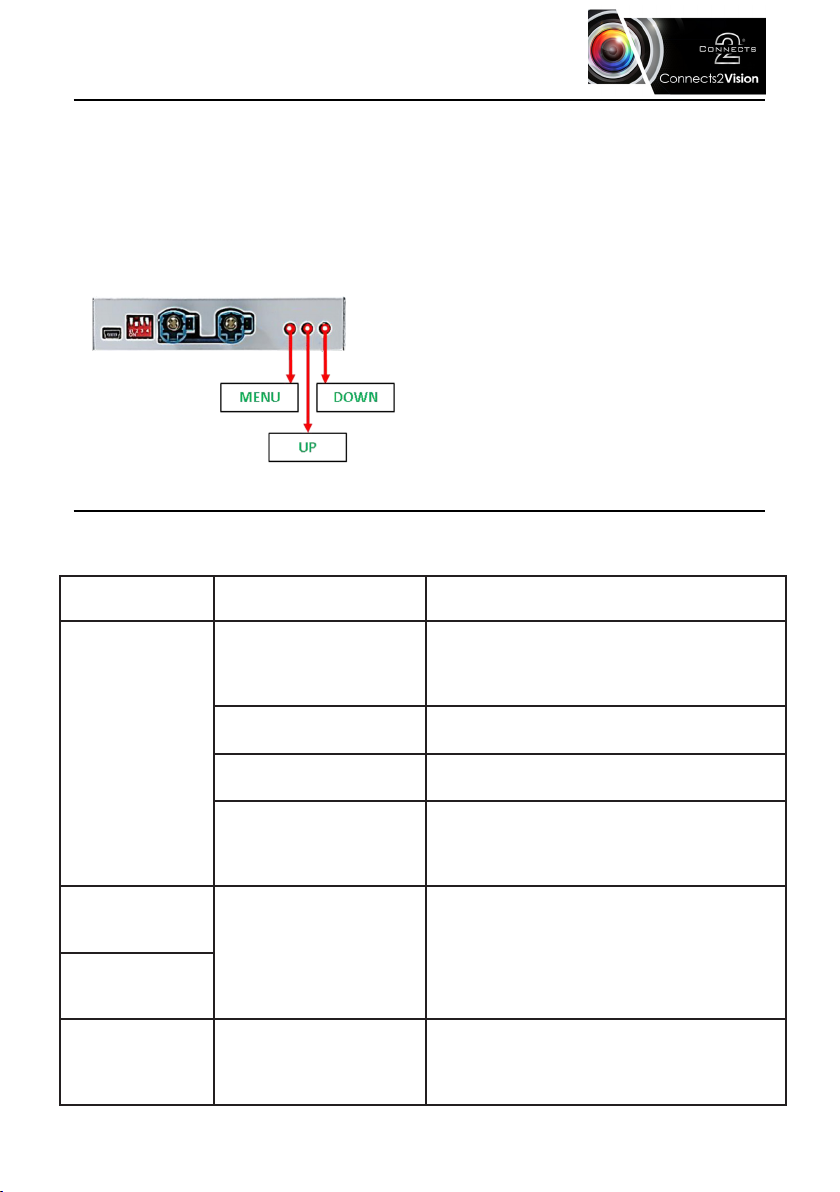
To ensure optimum appearance and functionality of the CAM-LR8-AD with
connected video sources, you are able to use the following 3 in-set buttons on
the rear of the interface. With the particular video source connected and
selected/engaged, press the ‘Menu’ button to view a list of settings that are
able to alter the brightness, contrast and look of the video source. Below are a
list of the following settings that are available:
•Contrast - 0 to 100 Contrast level
•Brightness - 0 to 100 Brightness level
•Saturation - 0 to 100 Saturation level
•Position H - No function
•Position V - No function
•IR-AV1/2 - No function
•Guide L/R - No function
•UI-CNTRL - Guidelines ON/OFF
•Size H/V - No function
Note: if there is no communication between the interface and the vehicle’s CAN-Bus, the reverse
guidelines cannot be shown during operation.
FAQ - TROUBLE SHOOTING
For any common problems, please refer to the troubleshooting table below or
contact our technical team via: support.connects2.com/tickets/technical/
Symptom Reason Possible Solution
No picture/black
picture (factory
picture).
Not all connectors have
been reconnected to
the factory head unit or
monitor after installation
Connect missing connectors according to
diagram on page 3.
No power on CAN-Bus
box (all LED’s are off) Check power supply of CAN-Bus.
CAN-Bus box connected
to wrong place.
Refer to the page 3 on where to connect
the CAN-bus connector.
No power on the video
interface (LED’s are off).
Check whether CAN-bus box delivers +12V
ACC on red wire output of 8pin to 6pin
cable. If not cut wire and supply ACC +12V
directly to video-interface.
Inserted picture
totally wrong size
or position. Wrong monitor settings
of video-interface.
Try different combinations of dips 7 and 8
of video-interface. Unplug 6pin power after
each change.
Inserted picture
double or 4 times
on monitor.
Graphics of a car
in camera input
picture.
Function PDC is ON in
the interface OSD.
In compatible vehicles, the graphics will
display the factory PDC distance. If not
working or not wanted, set interface OSD
menu item UI-CNTRL to ALLOFF.

8www.c2vision-eu.com
FAQ - TROUBLE SHOOTING
Symptom Reason Possible Solution
Inserted picture is
distorted, ickering
or running vertically.
Video sources output
set to AUTO or MULTI
which causes a conict
with the interfaces auto
detection.
Set video source output xed to PAL or
NTSC. It is best to set all video sources to
the same standard.
If error occurs only
after source switching:
connected sources are
not set to the same TV
standard.
Set all of the video sources to the same
standard.
Inserted picture
quality bad.
Picture settings have not
been adjusted
Use 3 buttons on the rear of the interface
to access the OSD and adjust any/all
picture settings for the corresponding
video input.
Inserted picture size
wrong.
Inserted picture
position wrong.
Camera input
picture ickers.
Camera is being tested
under uorescent light
which shines directly into
the camera.
Test camera under natural light outside
the garage.
Camera input
picture is bluish.
Protection sticker not
removed from camera
lens.
Remove protection sticker from lens.
Camera input
picture is black. Camera power taken
directly from reverse
gear lamp.
Use relay or electronics to “clean”
reverse gear lamp power. Alternatively, if
CAN-bus is compatible with the vehicle,
camera power can be taken from green
wire of 6pin to 8pin cable.
Camera input
picture is distorted.
Camera input
picture settings
cannot be adjusted.
Camera input picture
settings can only be
adjusted in AV2 mode.
Set dip 3 of video interface to ON (if not
input AV2 is not activate) and connect
the camera to AV2. Switch to AV2 and
adjust settings. Reconnect camera to
camera input and deactivate AV2.
Not possible to
switch video sources
by OEM button.
Vehicle CAN-Bus does
not support this function.
Use external keypad or cut white wire
of 6pin to 8pin cable and apply +12V
impulses for AV-switching.
Pressed too short. For video source switching a longer press
of about 2.5 seconds is required.
Not possible to
switch video sources
by external keypad.
SW-version of interface
does not support
external keypad.
Use OEM-button or cut white wire of 6pin
to 8pin cable and apply +12V impulses
for AV-switching.
Table of contents
Other Connects2 Camera Accessories manuals