Constructor HI280 User manual

USER AND ASSEMBLY GUIDE FOR
SMALL PARTS RACK HI280
Read this user guide carefully through before the small
parts rack is taken into use, and apply the information
continuously throughout the entire lifecycle of the rack.

Thanks for choosing small parts racking from Constructor.
It is of greatest importance that you follow the instructions in this guide in order for your rack to meet your require-
ments and to comply with the current standard.
The purpose of this guide is to inform the company’s warehouse staff and management about important facts
regarding the small parts rack, as well as precautions against potential danger risks.
If you have any questions, please contact us for further information.
The condition of the small parts rack in terms of security is best maintained through regular inspections and main-
tenance.
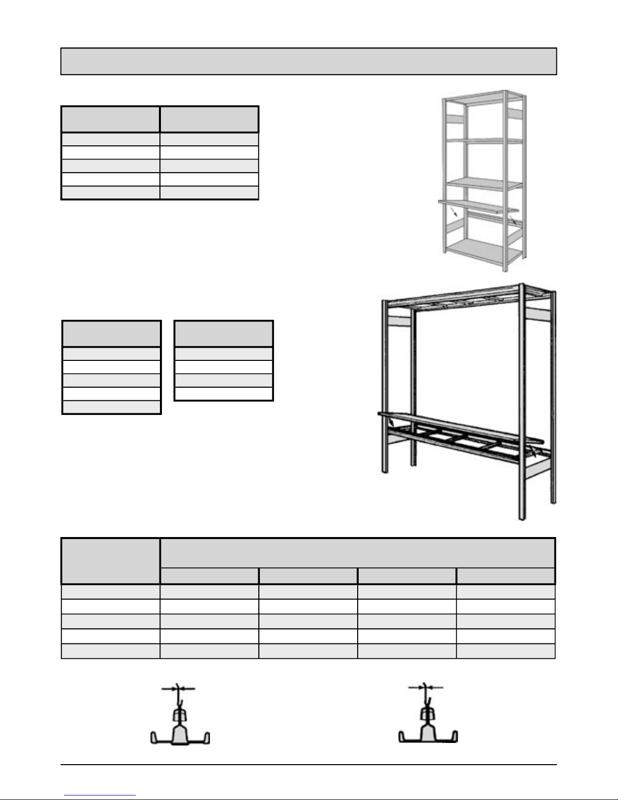
As for shelf and sections loads we refer to the load sign for each individual installation.
Each installation must be provided with a load sign.
page
- Technical data
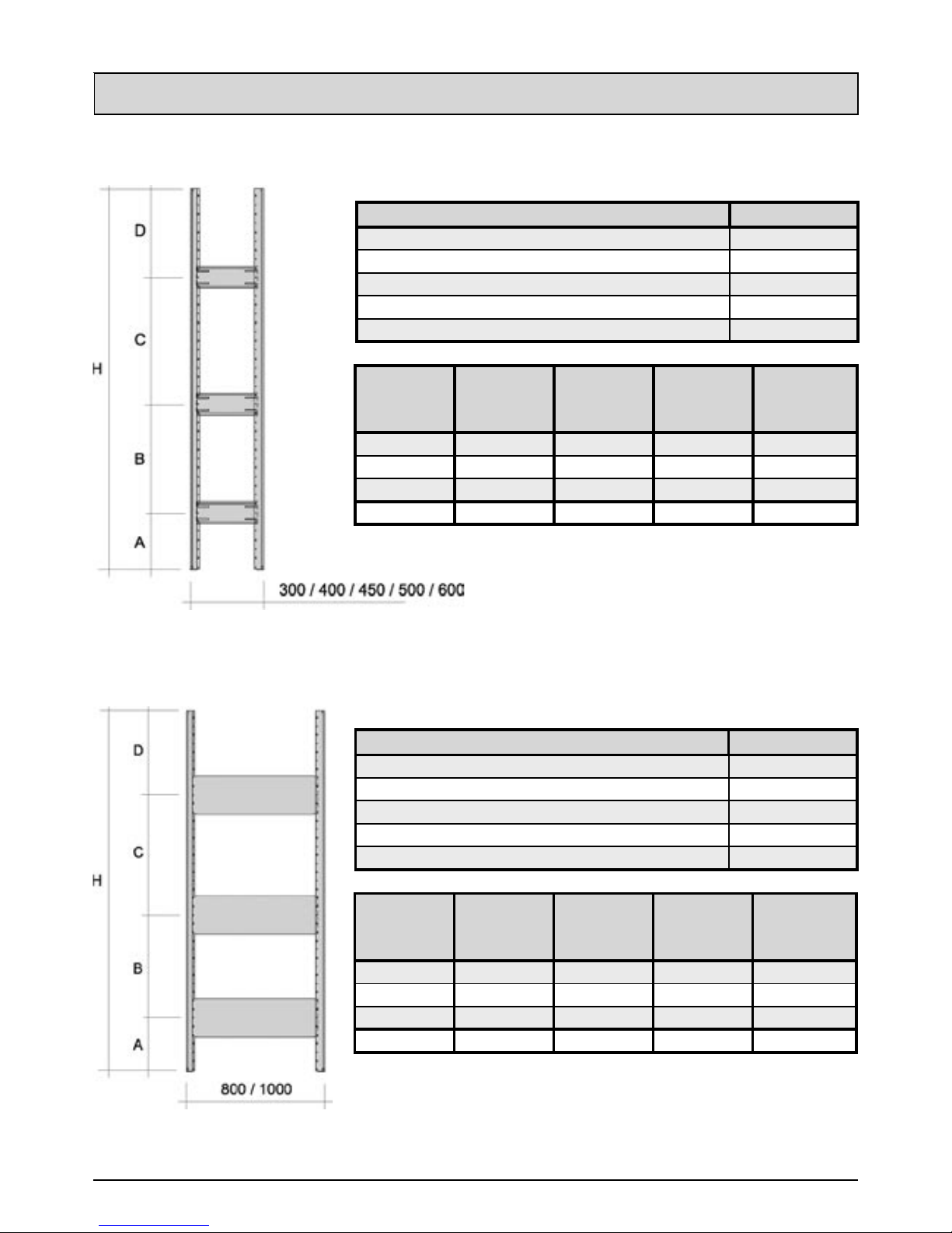
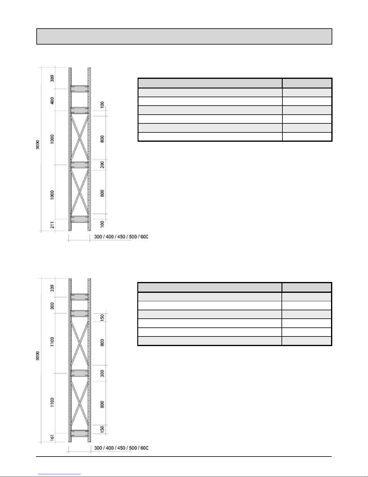
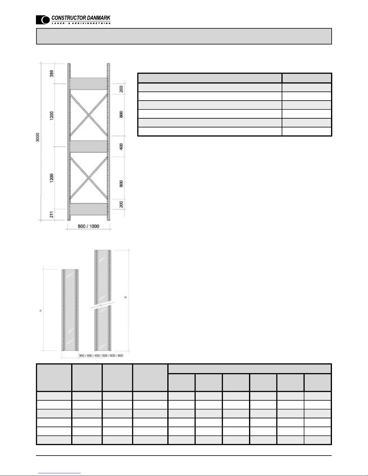
Shelves, medium span, recommended cross beams, upright types 3
Stay plates 4-8
- Assembly guide
Frame stay / stay plates 9
Frame plate 10
Frame mesh 11
Base 12
Shelf and support beams 13
Shelves / support shelves 14
Back cross / back mesh / double rack 15
Door 16
Suspension trays and shelves 17
Reinforced shelves 18
Accessories 19
Working bench / tools panel / ttings 20
- Important control points 21
- Security issues 22
- Protocol for periodical control of the small parts rack 23
Contents
2

Technical data
Shelf length
(mm)
Shelf depth
(mm)
900 / 1000 300 - 500
900 / 1000 600
900 / 1000 800
1290 300 - 500
1290 600 - 800
Shelves
Length per
section
Frame depth
mm 500 mm 600 mm 800 mm 1000 mm
1500 310 kg 370 kg 390 kg 390 kg
1750 360 kg 435 kg 520 kg 520 kg
2000 415 kg 490 kg 490 kg 490 kg
2250 400 kg 400 kg 400 kg 400 kg
2500 330 kg 330 kg 330 kg 330 kg
Upright types
KEK
Recommended no. of cross beams Medium span
3
Small parts rack HI280
Length per section
(mm)
Frame depth
(mm)
1500 500
1750 600
2000 800
2250 1000
2500
Medium span

Technical data
Small parts rack - 2 stay plates assembled with key
Components Quantity
Upright 2
Foot plate 2
Anchoring in oor (when required) 2
Stay plate 2
Popnit 4,8 x 9 mm (only for popnitted frames) 8
Frame
height
H
Distance
measures
A
Distance
measures
B
Distance
measures
C
1000 mm 211 600 189
1600 mm 311 800 489
2100 mm 311 1300 489
2300 mm 311 1500 489
2500 mm 311 1700 489
Small parts rack - 2 stay plates, popnitted
Components Quantity
Upright 2
Foot plate 2
Anchoring in oor (when required) 2
Stay plate 2
Popnit 4,8 x 9 mm 12
Frame
height
H
Distance
measures
A
Distance
measures
B
Distance
measures
C
1000 mm 211 600 189
1600 mm 211 900 489
2100 mm 311 1300 489
2300 mm 311 1500 489
2500 mm 311 1700 489
4

Technical data
Small parts rack - 3 stay plates assembled with key
Components Quantity
Upright 2
Foot plate 2
Anchoring in oor (when required) 2
Stay plate 3
Popnit 4,8 x 9 mm (only for popnitted frames) 12
Frame
height
H
Distance
measures
A
Distance
measures
B
Distance
measures
C
Distance
measures
D
2100 mm 311 600 700 489
2300 mm 311 600 900 489
2500 mm 311 700 1000 489
3000 mm 311 900 1300 489
Small parts rack - 3 stay plates, popnitted
Components Quantity
Upright 2
Foot plate 2
Anchoring in oor (when required) 2
Stay plate 3
Popnit 4,8 x 9 mm 18
Frame
height
H
Distance
measures
A
Distance
measures
B
Distance
measures
C
Distance
measures
D
2100 mm 311 600 700 489
2300 mm 311 600 900 489
2500 mm 311 700 1000 489
3000 mm 311 900 1300 489
5
Small parts rack HI280

Technical data
Small parts rack - 4 stay plates assembled with key
Components Quantity
Upright 2
Foot plate 2
Anchoring in oor (when required) 2
Stay plate 4
Popnit 4,8 x 9 mm (only for popnitted frames) 16
Frame
height
H
Distan-
ce
meas.
A
Distan-
ce
meas.
B
Distan-
ce
meas.
C
Distan-
ce
meas.
D
Distan-
ce
meas.
E
2100 mm 211 400 500 500 489
2300 mm 211 400 500 700 489
2500 mm 211 400 600 800 489
3000 mm 311 500 800 900 489
Small parts rack - 4 stay plates, popnitted
Components Quantity
Upright 2
Foot plate 2
Anchoring in oor (when required) 2
Stay plate 4
Popnit 4,8 x 9 mm 24
Frame
height
H
Distan-
ce
meas.
A
Distan-
ce
meas.
B
Distan-
ce
meas.
C
Distan-
ce
meas.
D
Distan-
ce
meas.
E
2100 mm 211 400 500 500 489
2300 mm 211 400 500 700 489
2500 mm 211 400 600 800 489
3000 mm 311 500 800 900 489
6

Technical data
Small parts rack - 4 stay plates, assembled with key + 2 frame cross
Components Quantity
Upright 2
Foot plate 2
Anchoring in oor (when required) 2
Stay plate 4
Gavelstag 4
Popnit 4,8 x 9 mm 8
Small parts rack - 4 stay plates, popnitted + 2 frame cross
Components Quantity
Upright 2
Foot plate 2
Anchoring in oor (when required) 2
Stay plate (hul popnit) 4
Frame cross 4
Popnit 4,8 x 9 mm 24
7
Small parts rack HI280

Technical data
Small parts rack - 3 stay plates, popnitted + 2 frame cross
Components Quantity
Upright 2
Foot plate 2
Anchoring in oor (when required) 2
Stay plate 3
Frame cross 4
Popnit 4,8 x 9 mm 26
Small parts rack with closed frame
Frame No. of Pro le No. of Types of frame plates
height
H
frame
plates
frame
plate
holes for
xing
900
mm
1000
mm
1600
mm
2100
mm
2300
mm
2500
mm
1000 mm 1 - 12 1
1600 mm 1 - 12 1
2100 mm 1 - 12 1
2300 mm 1 - 12 1
2500 mm 1 - 12 1
3000 mm 2 1 24 1 1
’H’ = Frame height
Each frame plate must be xed with 12 holes (6 for each upright), which
are placed at the top and bottom, the remaining holes are evenly distribu-
ted on the entire upright length.
For combination of frame plates for different frame heights, see table
below.
8

Assembly guide
Assembly of frames
In order to facilitate the assembly of frames, it is convenient to put them on a working bench or
table.
Frame cross / stay plate
Put the stay plate into the upright opening (1). Adjust the holes in the stay to the oval holes in
the upright (2). Make sure that the holes t together. Put the assembly key into the hole and turn
180° (3). Make sure that the connection on the back side is correct. All frame cross/stay
plates on rst upright must be assembled. Then the next upright is assembled (4). Finally, the
upright feet are assembled (5). Frame cross and stay plate 800 and 1000 are xed with a popnit
4,8 x 9. Frame stay is only required for special installations, e.g. heavy section loads and multi tier
installations.
Check that the feet are xed to the upright.
Small parts rack HI280
9

Assembly guide
Assembly of frame plate
Put the frame plate into the upright opening (1). Adjust the hole pattern in the frames to the
hole pattern in the uprights, so that the holes on the
frame plate ts into the oval holes in the
upright (2).
Put the assembly key into the oval hole and turn it 180° (3). Make sure that the
connection on the back side is correct. Sex holes per upright, one in each end, the other
evenly distributed, must be connected in this way
.
The frame plate must be assembled on one
upright, and then on the next upright. Finally the
upright feet are assembled (5)
.
Make sure that the upright feet are xed to the upright.
10

Assembly guide
Assembly of frame mesh
Mesh can only be assembled on frames which have already been assembled with stay plate or
frame cross. Mesh does not replace stay plate or frame cross. Place mesh and upright against
one another. The clips should be assembled on the mesh (1, 2), in the middle of the oval holes
in the uprights.
OBS! Turn the clips correctly. 4 clips should be assembled evenly distributed along the upright
with a clips in the upper and lower oval holes of the upright. Put the clips into the opening in
the upright (3) and make sure that the hole goes through the oval hole in the upright. Put the
assembly key into the hole and turn 180° (4). Make sure that the connection on the back
side is correct. Then the next upright should be assembled in the same way. Finally the upright
feet are assembled.
Make sure that the upright feet are xed to the upright.
Small parts rack HI280
11

Assembly guide
Assembly of base
Before assembly you must make sure that the cutting on the base and upright is not damaged.
The base should be assembled at the lowest end of the front upright on one of the frames. (1-
2). Make sure that the cuttings are well xed into the holes. Then the base on the other
frame should be assembled in the same way.
12

Assembly guide
Assembly of shelf and shelf beam
Before assembly, you must make sure that cuttings on shelf, shelf beam and upright are not
damaged. When you use base plate, the rst beam must be assembled in the fourth cutting from
the oor. Then the other beams are assembled. Use the oval and round holes in the upright in
order to facilitate the correct level. Make sure that the cutting are well xed.
OBS!
If the rack is to be equipped with suspension shelves or trays, or if the height (H) for the upper
loaded shelf exceeds 5 x shelf depth (D), the rack MUST be anchored in the oor with screws
and plugs to prevent it from tilting.
Small parts rack HI280
13

Assembly guide
Assembly of shelves
Before assembly, make sure that
the cuttings on shelves, shelf beam
and uprights are not damaged. The
shelf is assembled in steps from 1 to
4. At step 2 the shelf must be in ho-
risontal position. Use the hole pat-
tern in the uprights to nd this position.
Then make sure that the angle be-
tween the front of the small parts
rack and frame is 90°, before the shelf is
pressed down into the back cuttings of the
shelf beam and into the front cuttings of the
upright.
Make sure that the cuttings are
well xed.
Make sure that the rack is correctly assembled
by checking if the little hole in the shelf beam is
lying in front of the hole in the shelf edge.
Then the top shelf is assembled in the same
way, and hereafter the other shelves. Assembly of shelf to medium span
See Assembly of shelf.
Support shelf of chipboard:
Hang the cross beam between the two long
span beams in the cuttings of the beams, but
with a cross beam in each end, and the other
with a distance of max 500 mm.
Support shelf (mesh):
Put the mesh shelf between the long span
beams and press it down into the cuttings
of the beams. Make sure that the shelf is
resting in the cuttings.
Support shelf of steel:
Put the steel shelf between the beams and
press it down into the cuttings on the beams.
Make sure that the shelf is resting in the
cuttings. Put in the shelves according to the
table below for the different shelf lengths.
Shelf length Support shelf: placering and bredde
1500 246-246-246-246-246-246
1750 129-246-246-246-246-246-246-129
2000 246-246-246-246-246-246-246-246
2250 129-246-246-246-246-246-246-246-246-129
2500 258-246-246-246-246-246-246-246-246-258
14

Assembly guide
Assembly of double rack
The back uprights are put together by means
of a screw and nut in the top and bottom at
heights of max 3000 mm. If the rack is higher,
the max distance is 2000 mm between xings.
Use M6x20 mm. In case of a K upright you
need to drill a hole on site for coupling. If the
oor is uneven, levelling plates are placed
under the feet, so that all uprights are placed
on the oor and does not hang in the air, when
the rack is not loaded.
Assembly of back plate, split
Put the back plates on a plane surface facing
each other for the oval punched holes to t into
the oval holes (not punched). The plates are
assembled by putting the assembly key into the
punched holes and turn it 180˚.
Make sure that the plates are punched
together.
Assembly of back plate/back mesh
Place back plate/back mesh between the back
uprights of the small parts rack. Fix four clips
on each side of the back plate/back mesh and
press the clips onto the upright according to
drwg 1 and 2.
Assembly of back plate, whole
When you use more than one back plate in the
height, the connection must be covered with a
connection prole.
Use 6 clips for each back plate with the height
800, 1000, 1200 and 1300 mm.
Small parts rack HI280
15

Assembly guide
Assembly of door with built-in handle
Bottom piece for bottom shelf should be assem-
bled with the xing ttings (plastic). Place the
doors for the bottom piece. Take the top piece
and place it over the doors. Then the top piece
for the top shelf should be assembled using the
xing ttings (plastic).
Assembly of door with outside handle
Put in a top/bottom piece (A) on to the lower shelf (1-2). Lift the upper somewhat, and place
a top/bottom piece (B) in the same way (3). Keep this in place. Place a door plate (C) with the
lower hinge in the hole of the lower top/bottom piece (A). Adjust the upper top/bottom piece (B)
on the doors upper hinge (4-5). Then the other door plate must be assembled in the same way.
Put the top shelf (D) back into place. Hereafter you lock the top shelf with a foot plate (E) in
each upright (6). Lock and accessories should be assembled.
16

Assembly guide
Assembly of suspension trays and shelves
The four ttings in the upright should be assembled (1-2). If you need to assemble more ttings
on to each other, you assemble the lower tting rst. Then you assemble the expansion ttings by
putting the back cutting of the tting into the tting of the back upright. Then you hang the front
crook of the expansion tting into the tting of the rst upright. Pull out the expansion ttings and
hang the trays/shelves on to the cuttings of the expansion ttings.
OBS! Racks with suspension trays or shelves must be anchored into the oor in order
to prevent it from tilting.
Fix the ttings to the uprights with screw M6x20 and nut M6.
Small parts rack HI280
17

Assembly guide
Assembly of reinforced shelves
The shelf beams should be assembled between the back uprights, and then the cross reinforce-
ments between back and front upright. Then hang the lenghtwise reinforcements into the
crosswise, one in the middle, alternatively two in the ends, into the cuttings found. As to the
quantity, we refer to the load tables. Then place the shelf.
Make sure that the cuttings in the shelf beams, cross reinforcements and shelf are
well xed into the uprights.
18

Assembly guide
Assembly of accessories
Assemble the different accessories by following the drawings shown. Make sure that the cuttings
in beams and proles are well xed.
Small parts rack HI280
19

Assembly guide
Working bench, tools panel and ttings
Working bench and tools panel should be assembled in the order (1-9) shown on above drawings.
Stop (2) must be assembled at the far end of the table top’s short sides.
Make sure that the cuttings in beams and reinforcement proles are well xed.
20
Table of contents
Popular Indoor Furnishing manuals by other brands

Habitat
Habitat Pacha 823786 quick start guide

Fellowes
Fellowes C.S. Ergonomics RH 300 brochure

INTER LINK SAS
INTER LINK SAS AMSTERDAM 30 70 05 00 Assembling Instruction

Pacific Casual
Pacific Casual Palm Beach 211-WM0-DT-EXT Use and care guide

Target
Target 5948307T Assembly instructions

CARRARO
CARRARO 1086 manual

hygena
hygena Matrix Glass Coffee Table 610/8267 Assembly instructions

MMSzynaka Interline
MMSzynaka Interline VIEVIEN Assembly instruction

ETI
ETI WP-78-850-MV Use and care guide

Core Products
Core Products Corona CR520 Instruction leaflet

VIBO
VIBO NES P.240 Assembling instructions

Monarch
Monarch I 1135 Assebly instructions