Lec+ Club Chair V2 User manual

INSTALLATION MANUAL
1-400-0065 • Rev A • 6/20/18
© Living Earth Crafts 2018, All Rights Reserved
*all chairs shown with oponal accessories and/or nishes
Club Chair V2
Mystia
5th Avenue
Pedicure Chairs with
Plumbed Tubs

© Copyright 2018
Living Earth Cras®
All rights reserved. is document or any
portion thereof may not be reproduced
in any way, including photocopying or
translation to another language without
the prior written permission from Living
Earth Cras.
Living Earth Cras® is a registered trade-
mark of Earthlite, LLC.
Legal Notice
e information provided in this document is intended
for informational purposes only and is subject to change
without notice. e information provided in this docu-
ment should not be construed as a commitment by
Living Earth Cras®.
Living Earth Cras® assumes no responsibility for the
accuracy or suitability of the information contained in
this document. is document may contain technical
inaccuracies or errors. Living Earth Cras® makes no
expressed or implied warranties of any kind concerning
the information contained in this document, including,
but not limited to, the implied warranties of merchant-
ability and tness for purpose.
Living Earth Cras® shall not be liable for incidental or
consequential damages in connection with or arising out
of the product, performance, or use of this document
and the information and material it describes.

Introduction
Congratulaons on your purchase of the Club Chair V2, Mysa, or 5th Avenue pedicure chair. This
manual is designed to be given to the licensed plumbers, electricians, and any other technicians
performing the installaon of your pedicure chairs.
Installer(s): Please review this manual in detail before beginning installaon, and follow all safety
warnings, labels, and instrucons. If you have quesons, please contact Living Earth Cras at
(800) 872-0560 for US customers, or (760) 597-2155 for internaonal customers. We can also be
reached via e-mail at info@livingearthcras.com
Secon 1: Safety Informaon
Safety Symbols & Warnings
Secon 2: Product Overview
Electrical Specicaons
Product Specicaons
Plumbed Tub Overview
Secon 3: Installaon
Chair Specic Diagrams
Swingaway Manicure Trays
Tub Dimensions
Tub Installaon Guidelines
Electrical/Plumbing
Drain Specicaon
Internal Tub Reference Photos
Backow Prevenon
Frequently Asked Quesons
Contact Us
2
3
4
5
6-8
9
10
11
12-13
14
15
16
17
Table of Contents
back cover

READ AND SAVE THESE INSTRUCTIONS
2
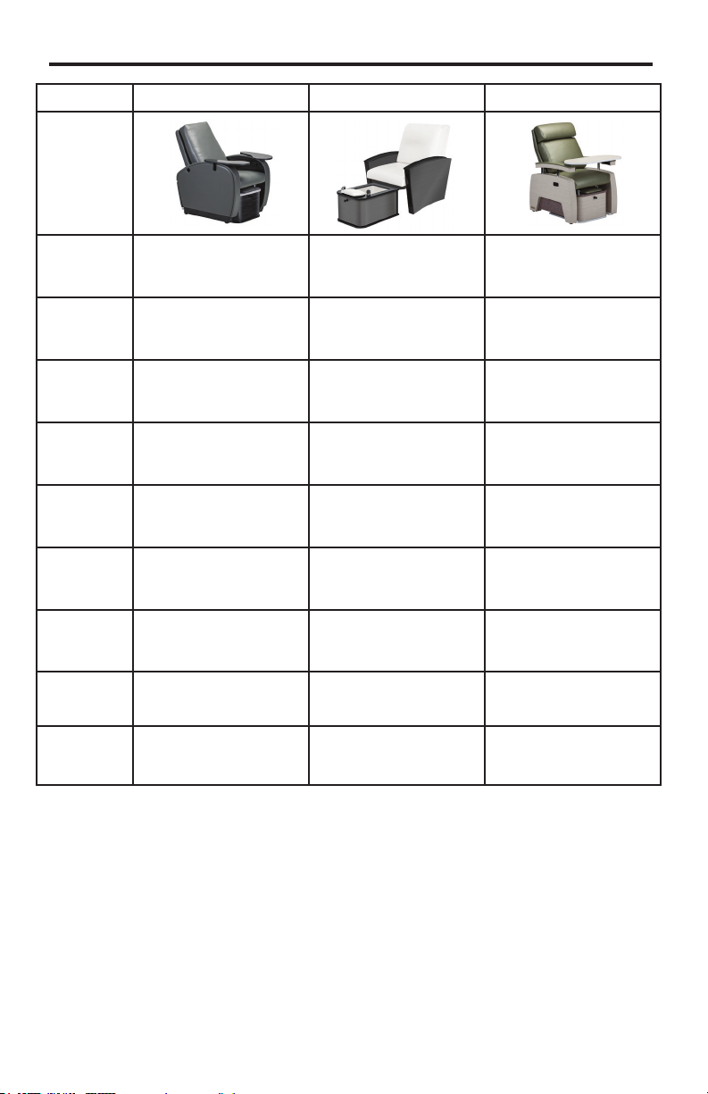
IMPORTANT SAFETY INSTRUCTIONS - FOR COMMERCIAL USE ONLY
Read all instructions before using this product.
Safety Symbols
Familiarize yourself with the following
Safety & Warning symbols. They are
designed to prevent damage and injury to
you, your clients, and your new Earthlite
product.
IMPORTANT: The important safety
instructions and warnings in this manual
cannot cover all possible problems and
conditions that can occur. Use common
sense and caution when installing,
operating, or maintaining this appliance.
Indicates an imminently hazardous
situation which could result in serious
or fatal injury.
Indicates a potentially hazardous
situation which could result in serious
injury.
Indicates a potentially hazardous
situation which could result in
equipment damage and/or injury.
SECTION 1: SAFETY INFORMATION
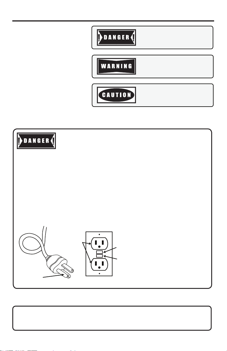
1. RISK OF ELECTRIC SHOCK. Connect only to a circuit protected by a ground-fault
circuit-interrupter.
2. Grounding is required. The unit should be installed by a qualied service
representative and grounded.
This product must be grounded. If it should malfunction or break down, grounding provides a path of
least resistance for electric current to reduce the risk of electric shock. This product is equipped with
a cord having an equipment-grounding conductor and grounding plug. The plug must be plugged into
an appropriate outlet that is properly installed and grounded in accordance with all local codes and
ordinances.
Improper connection of the equipment-grounding connector can result in a risk of electric shock. Check
with a qualied electrician or serviceman if you are in doubt as to whether the product is properly grounded.
Do not modify the plug provided with the product - if it will not t the outlet, have a proper outlet installed by
a qualied electrician.
INSTALLATION INSTRUCTIONS / GROUNDING INSTRUCTIONS
Reset
Button
GFCI Outlet
Grounding Pin
Test
Button
See User Manual for all safety information and warnings pertaining to use of this product.
INSTALLER/OWNER BEARS ALL RESPONSIBILITIES TO COMPLY WITH STATE
AND LOCAL CODES WHEN INSTALLING THIS PRODUCT. FAILURE TO COMPLY
WITH THESE INSTRUCTIONS MAY VOID WARRANTY.

Electrical Specications
Spec North America Europe/Asia
Input Voltage 120 VAC 220 VAC
Input Frequency 60 Hz 50 Hz
Total Consumpon - All
Opons 9.5 Amps Max 5.2 Amps Max
Consumpon - Chair &
Hydrotherapy Tub Only 4 Amps Max 2.2 Amps Max
Consumpon - Relaxor Addional 4 Amps (Max) Addional 2.2 Amps (Max)
Consumpon - Discharge
Pump Addional 1.5 Amps (Max) Addional 0.8 Amps (Max)
SECTION 2: PRODUCT OVERVIEW
Discharge Pump Specication
Motor Design Single-phase synchronous motor
Flow Rate 120V: 24 l/min at 0, 1 bar; 220V: 20 l/min at 0, 1 bar
Duty Cycle Connuous
Sanijet® Jet System Specication
Motor Design Single speed, electronic spherical DC motor w/magnec rotor impeller
Motor Materials Thermoplasc jet, motor, case assembly; stainless steel rotor impeller
Safety Features Safety shuto sensor, dry-run/thermal overload protecon
Supply & Drain Specication
Supply Connecons 1/2” NPT (Recommended) / 1.27 cm
Drain Outlet 1.5” / 3.81 cm
3

Club Chair V2 Mysa 5th Avenue
Product
Image*
Chair Overall
Dimensions 49”H x 32”W x 38.5”D 45.5”H x 30.25”W x 35”D 48”H x 32”W x 36.75”D
Tub Overall
Dimensions 15.5”H x 22”W x 26.5”D 15.5”H x 22”W x 26.5”D 15.5”H x 22”W x 26.5”D
Tub Basin
DImensions 9”D x 14.75”W x 15”L 9”D x 14.75”W x 15”L 9”D x 14.75”W x 15”L
Seat Height
(from oor) 24” H 24” H 24” H
Locaon of
Tilt Lever
(Oponal)
Inside panel on the right-
hand side
Outside panel on the
right-hand side
Outside panel on the
right-hand side
Tilt Angle
(Oponal) 20 degree lt range 20 degree lt range 20 degree lt range
Cushioning Strata™ Memory Foam
Cushioning System
Strata™ Memory Foam
Cushioning System
Strata™ Memory Foam
Cushioning System
Upholstery Naturso® Naturso® Ultraleather® or Promessa®
Other
Opons
Relaxor® Heat/Massage
DIscharge Pump
Swingaway Nail Trays
Relaxor® Heat/Massage
DIscharge Pump
Swingaway Nail Trays
Relaxor® Heat/Massage
DIscharge Pump
Swingaway Nail Trays
SECTION 2: PRODUCT OVERVIEW
*all products shown with oponal accessories and/or nishes. Measurements may vary due to natural material variaons
4

5
SECTION 2: PRODUCT OVERVIEW
Plumbed Tub Overview
Footrest
Adjustment
Knob
Power Buon - Lights*
Power Buon - Jets*
Power Buon - Discharge
Pump (Oponal)
Remote Drain
Handle
Tub Basin
Water Control
Valve (Fill &
Temperature)
Drain
Light*
Jets*
Sprayer/Fill
Reexology*
*Features are on hydrotherapy tub only

SECTION 3: INSTALLATION
THE FOLLOWING TECHNICAL DIAGRAMS SHOULD BE GIVEN TO YOUR ENGINEERS,
ARCHITECTS, DESIGNERS, ELECTRICIANS & PLUMBERS.
Failure to comply with federal, state, or local codes and ordinances could result in the
voiding of product warranty as well as potential injury and ooding. A licensed plumber
should make all utility connections. All plumbing connections must conform to local
codes. Water temperature/pressure should not exceed local regulations.
The following footprint establishes the MINIMUM recommendations.
• Note: The oor has to be capable of supporting the expected load - minimum 200 lbs.
• Note: If your chair has back tilt, a minimum of 12” should be between the wall and the back of the
chair when upright which will allow the chair to tilt back to its farthest point.
• Note: The soaking tub will not have the hydrotherapy jets installed. Plumbing and electrical
connections are the same.
Club Chair V2
50.5”
76.5”
38.5” 15.75”
12”
center of drain
wall to end of tub
wall to center of drain
Wall
66.25”
6

SECTION 3: INSTALLATION
5th Avenue
THE FOLLOWING TECHNICAL DIAGRAMS SHOULD BE GIVEN TO YOUR ENGINEERS,
ARCHITECTS, DESIGNERS, ELECTRICIANS, & PLUMBERS.
Failure to comply with federal, state, or local codes and ordinances could result in the
voiding of product warranty as well as potential injury and ooding. A licensed plumber
should make all utility connections. All plumbing connections must conform to local
codes. Water temperature/pressure should not exceed local regulations.
The following foot print establishes the MINIMUM recommendations.
• Note: The oor has to be capable of supporting the expected load - minimum 200 lbs.
• Note: If your chair has back tilt, a minimum of 12” should be between the wall and the back of
the chair when upright which will allow the chair to tilt back to its farthest point.
• Note: The soaking tub will not have the hydrotherapy jets installed. Plumbing and electrical
connections are the same.
Wall
wall to end of tub
36.75”
12”
12”
center of drain
74.75”
wall to center of drain
64.5”
7
15.75”

SECTION 3: INSTALLATION
Mystia
THE FOLLOWING TECHNICAL DIAGRAMS SHOULD BE GIVEN TO YOUR ENGINEERS,
ARCHITECTS, DESIGNERS, ELECTRICIANS & PLUMBERS.
Failure to comply with federal, state, or local codes and ordinances could result in the
voiding of product warranty as well as potential injury and ooding. A licensed plumber
should make all utility connections. All plumbing connections must conform to local
codes. Water temperature/pressure should not exceed local regulations.
The following footprint establishes the MINIMUM recommendations.
• Note: The oor has to be capable of supporting the expected load - mimimum 200 lbs.
• Note: If your chair has back tilt, a minimum of 10” should be between the wall and the back of
the chair when upright which will allow the chair to tilt back to its farthest point.
• Note: The soaking tub will not have the hydrotherapy jets installed. Plumbing and electrical
connections are the same.
center of drain
45”
15.75”
71”
60.75”
35”
10”
wall to end of tub
wall to center of drain
Wall
8

SECTION 3: INSTALLATION
Swingaway Manicure Trays (Optional)
The Swingaway Manicure Trays may need to be taken into account when determining spacing
between chairs. See below dimensions and posioning examples for reference.
11.5”
23.5”
11.5”
23.5”
The manicure trays can easily be swiveled to any posion that is desired. Below are the most
commonly used tray posions and their funcons.
Posion 1: Places trays closer to the client and allows the magnec center tray to be aached.
Posion 2: Places trays closer to the technician and provides more room for the client.
Posion 3: Allows the trays to funcon as extended armrests or table.
position 1 position 2 position 3
Overhead view
Tray Positioning
9

SECTION 3: INSTALLATION
Tub Dimensions - Top View
15”
26”
22”
4”x 6”
Tub Dimensions - Side View
26”
11”
15.75”
15”
oor oor
10

SECTION 3: INSTALLATION
Tub Installation & Anchoring Guidelines
2. Remove back access panel and set aside
3. Gently place tub on its side and locate the nut securing the drain handle.
4. Using a crescent wrench, loosen the nut and remove the drain handle. (Fig. 3)
1. Remove 4 screws on back access panel, and 2 screws from the drain handle plate. (Screws
are indicated by the blue circles in Fig. 1 and Fig. 2 below.)
Fig. 1
Fig. 3 Fig. 4
5. Loosen the Velcro securing the shroud, and remove the shroud completely from the tub.
6. Place the tub exactly where it needs to be anchored to the oor (see installaon diagrams
on pages 16-18 for measurements).
7. Locate the 4 pre-drilled anchor holes in the HDPE tub base (Fig 4). Using a marker, mark
these 4 points on the oor.
8. Move tub and drill anchor holes (recommended size: 1/2”) and install anchors.
9. Replace tub, lining up pre-drilled anchor holes over the anchors.
10. Tighten a nut on each anchor to secure tub to the oor.
NOTE: We recommend having a licensed plumber make all the plumbing connecons at this
point, before re-installing the shroud and drain handle.
11. Replace shroud and re-install drain handle.
12. Replace the back access panel (4 screws), and drain handle plate (2 screws).
Fig. 2
11

SECTION 3: INSTALLATION
Power Cord
(8 ft long)
Cold Water Connection
(1/2” female pipe thread)
Hot Water Connection
(1/2” female pipe thread)
Drain/Discharge
Pump Connection
(1” female pipe thread)
Option 1 - Plumbed to the Wall
Use this opon if your hot and cold water supply and drain line will be coming from the wall,
behind the pedicure chair. For this opon, all the internal plumbing connecons have already
been made for you. Aer the tub has been anchored (see instrucons on page 21), all the
plumber will need to do is connect the hot water supply line, cold water supply line, and the
drain line to the rear manifold.
Plumbing/Water Supply
• All plumbing connecons, including the drain, must conform to all state and local codes.
• Maximum suggested operang temperature should not exceed 105°F (41°C), and the
maximum suggested supply water temperature should not exceed 120°F (49°C). State
and local codes may have dierent regulaons - please follow codes if dierent from
suggested temperatures.
• Carefully connect the water supply ngs. Shut-o valves are recommended.
• Water pressure must be 30-80 psi (206-551 kpa).
Electrical Service
• 110V/60 Hz or 220V/50 Hz GFCI protected grounded circuit must be used to supply
power to the pedicure tub.
• Cung o the end of the electrical plug to hardwire the spa is NOT recommended, and
can void the warranty. (See page 3 for grounding instrucons/safety warnings.)
• All wiring connecons have been done with unit assembly.
12

SECTION 3: INSTALLATION
Option 2 - Plumbed to the Floor
• Use this op on if your hot and cold water supply and drain line will be located in the
oor underneath the tub. For this op on, a licensed plumber will need to disconnect the
internal connec ons from the manifold and re-route the lines as needed.
• Release power cord from the strain relief (if needed) to be plug into a oor outlet.
• Before installa on, carefully review the diagrams and speci ca ons on pages 18-24 to
ensure all spacing and placement is correct.
• All CAD symbols are for representa on only. Correct connec ons are responsibility
of the purchaser, owner and/or its agents, installers, and should only be completed
by licensed professionals. Living Earth Cra s is not responsible for any incorrectly
interpreted, owner-installed water or electrical connec ons.
Tub - Top View
15”
26”
22”
4”x 6”
7” from drain center
14”
14”
If using a oor drain, locate within the red shaded area shown in the diagram below.
NOTE: Floor drain should be no larger than 8” x 8” (larger drains could protrude from the
bo om of the tub footprint).
Supply line should be taken into account prior to placement. The supply line area is shown
with the green shaded area in the diagram on the le . Supply lines need to be short enough
to clear the tub.
13

SECTION 3: INSTALLATION
Female 1.5” thread Male 1.25” thread
Male 2” thread
(Unit will ship with this
opening pre-connected to
the twist handle that opens/
closes the drain)
(IMPORTANT: Unit will ship with this opening capped o - plumbing
will need to be re-congured if using a gravity drain setup.)
(Unit will ship with this
opening pre-connected to an
elbow tting that attaches to
the discharge pump.)
Drain Specication
Item
Number Descripon
1 O-Ring, Plunger
2 Ferrule, Coupling Nut
3Nut, Coupling for Twist Drain
4Gasket, 3 1/2” Face Flange
5 Flange, 3 1/2” Face
6 Strainer, 3 1/2” Snap-in Removable
7 Plunger, Lever and Twist Drain
8 Rotary Waste Valve Twist Handle
9 Adapter, 2” NPT x 1 1/2” NPT
Drain Exploded Diagram
14

Internal Tub Reference Photos
SECTION 3: INSTALLATION
15

SECTION 3: INSTALLATION
Backow Prevention
DOUBLE CHECK VALVE INFORMATION
American Faucet & Coatings Corporation (PART #19.10.007)
Each pedicure tub comes with a dual backow preventave device pre-installed.
This device ulizes two (2) 15mm check valves that are cered to ANSI/NSF 61
and ASME A112.18.3 (see detailed specicaon from manufacturer on the next
page)The ASME A112.18.3 standard, in Secon 8.1.1, indicates that “there shall be
at least two backow prevenon devices, in series”. The double check valve shown
below, installed on the tub supply valve, fullls this requirement. The 2 check
valves are installed in series and operate independently, per the standard.The
placement prevents backow into both the hot and cold supply lines.
*see next page for detailed specication and
certication information
DOUBLE CHECK VALVE PLACEMENT
Hot & Cold
Supply Lines
Supply line to
tub ll/sprayer
Double Check
Valve
16

DOUBLE CHECK VALVE INFORMATION
American Faucet & Coatings Corporation (PART #19.10.007)
DOUBLE CHECK VALVE PLACEMENT
Does the tub have backow prevenon?
Yes - see pages 10-11 for backow prevenon details.
Do I sll have to install backow prevenon on my main water supply line?
This is enrely dependent on your local and/or state codes. A licensed plumber with knowledge of
your local and/or state codes can answer this queson for you.
Do we need to install a p-trap?
Check with the licensed plumber performing the install. It is dependent on your drain locaon.
Can you provide a leer to my city inspector stang my electrical and/or plumbing setup is
acceptable?
Unfortunately not. In this document, we have provided all the informaon that a licensed plumber
and electrician would need to perform the proper install that adheres to local and state codes. Living
Earth Cras does not have knowledge of all local and state codes and therefore is not qualied to
advise on individual setup quesons. If an inspector has quesons about how your plumbing and/
or electrical is being set up, you will need to contact your plumber and/or electrician.
Does the Contour have GFI/GFCI built in?
There are no GFI/GFCIs built in to the system - we require a GFCI protected grounded circuit to
supply power to the Contour.
Frequently Asked Questions
17
SECTION 3: INSTALLATION

Contact Us
Living Earth Crafts
990 Joshua Way
Vista, CA. 92081
(800) 358-8292
(760) 597-2155 Int’l
(866) 449-8872 fax
Hours of operation:
Monday - Friday
8:00 a.m. to 5 p.m. PST
Saturday - Sunday
Closed
Visit us online at: livingearthcrafts.com
Read our blog at: livingearthcrafts.com/blog
Join us on Facebook®
This manual suits for next models
2
Table of contents
Other Lec+ Indoor Furnishing manuals
Popular Indoor Furnishing manuals by other brands

INR
INR 170209 manual

Furniture of America
Furniture of America CM6450LV Assembly instructions

Amart Furniture
Amart Furniture SIGNATURE NERO 63760 Assembly instruction

Vidao
Vidao VW54C Assembly instructions

Bilt
Bilt TRINITY CTHA-0326 owner's manual

Hardware House
Hardware House St. Regis Assembly instructions

ROVO
ROVO FUN 2045 SR Assembly

Southern Enterprises
Southern Enterprises BC273100T Assembly instructions

Leto Muro
Leto Muro Abner Series installation instructions

VONDOM
VONDOM Delta 66006T Assembly instructions

John Lewis
John Lewis Martha Sleigh cotbed instruction manual

Ameriwood HOME
Ameriwood HOME 5046096COM manual