10
Loop Congurations / Set Up
PLEASE NOTE: The loop cable must be connected before powering up
the driver. Upon power up the loop is automatically analysed and set
up. If no loop is connected the status light will be solid red. To RESET
unplug the driver and wait 60 seconds minimum after all lights go out.
Perimeter Loop or Primary Driver Setup*
1. Power up the driver and once the loop analysis (indicated by the
ashing LED sequence) is complete, conrm or select the correct
driver type (PERIMETER or PRIMARY). Instructions on changing driver
type on page 14.
CAUTION: Once the loop (load) has been analysed it should not be
altered or adjusted
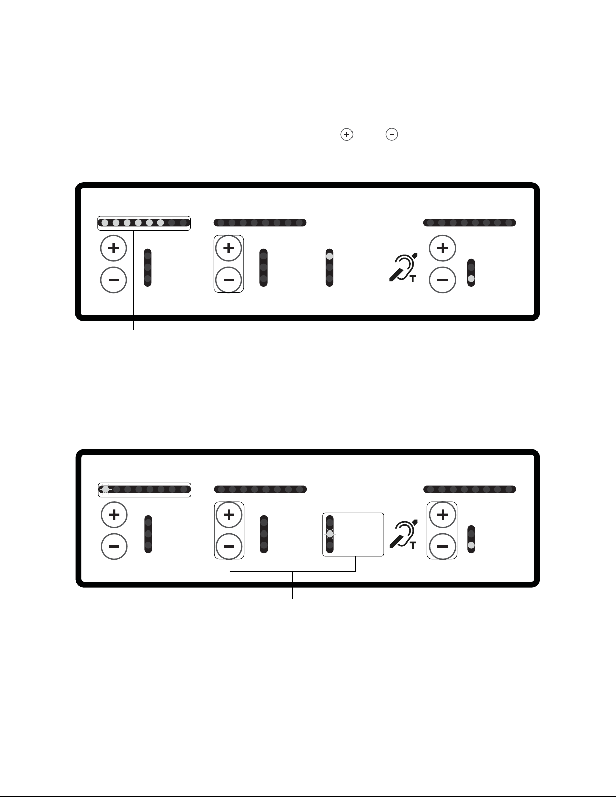
2. Enter the adjustment mode by pressing the MIC (+ and - ) buttons
simultaneously until the red status light ashes.
3. While in adjustment mode (red status light ashing) conrm that
the MIC, LINE and DRIVE levels are set to their minimum level by
individually holding in the - button of each for a few seconds.
4. Connect the input signal to the LINE input unless you are directly
connecting a microphone. If testing with our Test Signal Generator
(TSG), connect to the HLD9’s LINE input.
5. For either input signal (in adjustment mode) increase the
appropriate input level by pressing the - button until the rst yellow
LED illuminates (this will be solid if using a sine wave) or occasionally
ash if used on music or speech sources.
6. Bring the DRIVE level up by pressing the DRIVE + button until the
required level is reached.