6
1. CoLinkEx_LPC11C14 EVB Kit Overview
1.1 The Microcontroller Introduction
CoLinkEx_LPC11C14 EVB Kit uses the LPC11C14x301FBD48 for NXP. The LPC11Cxx
are ARM Cortex-M0 based microcontrollers for embedded applications featuring a high
level of integration and low power consumption.
The LPC11xx operate at CPU frequencies of up to 50 MHz, the peripheral complement of
the LPC11xx series includes up to 32KB of flash memory, up to 8 KB of data memory, one
Fast-mode Plus I2C-bus interface, one RS-485/EIA-485 UART, up to two SPI interfaces
with SSP features, four general purpose timers, a 10-bit ADC, and up to 42 general
purpose I/O pins. It integrated ARM Cortex-M0 built-in Nested Vectored Interrupt
Controller (NVIC), integrated PMU (Power Management Unit) to minimize power
consumption during Sleep, Deep-sleep, and Deep power-down modes.
The LPC11Cxx operates in the -40 to +85 °C temperature range, from a 1.8 to 3.6 V
power supply. A comprehensive set of power-saving mode allows the design of low-power
applications. It includes:
Emetering
Lighting
Industrial networking
Alarm systems
White goods
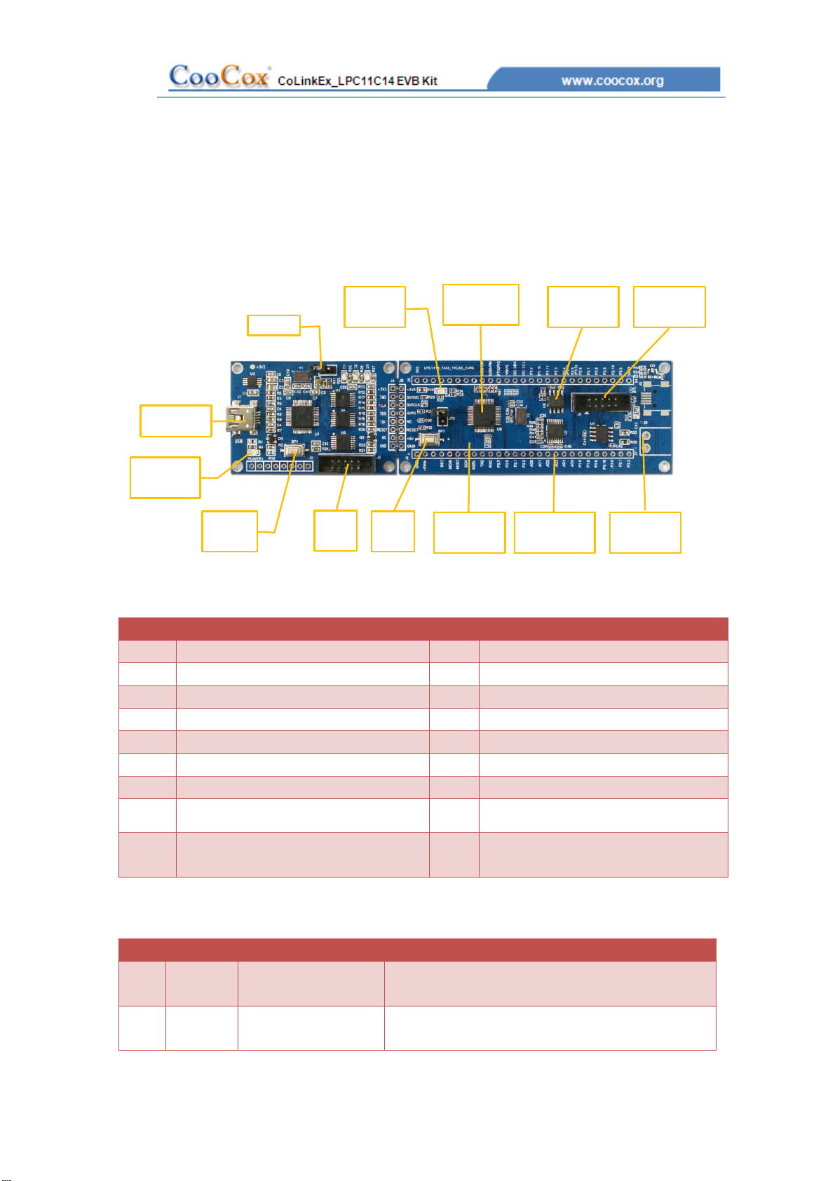
1.2 Evaluation Boards Introduction
CooCox’s CoLinkEx_LPC11C14 EVB Kit is a brand new, cost-effective but
high-performance evaluation tool of the ARM Cortex-M0 based LPC11xx controller family
from NXP, allowing you to create and test working programs for this advanced
architecture. The board has UART Interface which support RS-485 and EIA-485 modes, 8
channel 10 bit ADC Converter, 2 16bit timer and 2 32bit timer, includes a wide range of
interfaces such as SPI, I2C, integrates PMU(Power Manage Unit). It supports IO
extensions, which is compatible with LPCXpresso Base Board, making it a great starting
point for your next Cortex-M0 project. The onboard adapter: CoLinkEx support MDK and
IAR, help you execute download and debug the project.
You can use the CoLinkEx_LPC11C14 EVB Kit to generate and test application programs
for the NXP LPC11xx microcontroller family. The example and source in the CD will help
you quickly start project development and personal learning.