2
• Prima di dar inizio all’installazione leggere attentamente il presente fasci-
colo. In particolare, prendere visione dei dispositivi di sicurezza previsti
dal prodotto per utilizzarli con la massima efficacia.
• Non tutti i dispositivi di sicurezza eventualmente resi obbligatori da norme
vigenti in Italia o all’estero sono presi in considerazione dal presente
fascicolo. L’installatore dovrà provvedervi personalmente, integrando i
dispositivi mancanti ed installandoli a monte o a valle dei prodotti descritti
nel presente fascicolo.
• L’utilizzo dei prodotti e la loro destinazione ad usi diversi da quelli previsti
e/o consigliati, non è stata sperimentata dal costruttore, pertanto i lavori
eseguiti sono sotto la completa responsabilità dell’installatore.
• Il presente manuale si rivolge a persone abilitate all'installazione di "Appa-
recchi utilizzatori di energia elettrica" e richiede una buona conoscenza
della tecnica, esercitata in forma professionale. Il costruttore declina ogni
responsabilità per eventuali danni provocati dalla mancata osservanze
nel installazione della norme di sicurezza attualmente in vigore.
Attenzione! Il programmatore è utilizzabile esclusivamente
con i motori della Cardin Elettronica in bassa tensione delle
serie "EL 3024".
Programmatore per motore in corrente continua con ricevente incorporata,
che permette la memorizzazione di 300 codici utente (vedere "comando
via radio", a pag. 5). La decodifica è di tipo 'rolling code', e la frequenza di
funzionamento è di 433.92 MHz.
La velocità di rotazione del motore è controllata elettronicamente basandosi
sulle indicazioni dei finecorsa, con partenza lenta e successivo incremento;
la velocità viene ridotta con anticipo rispetto all'arrivo in battuta, in modo
da ottenere un arresto controllato.
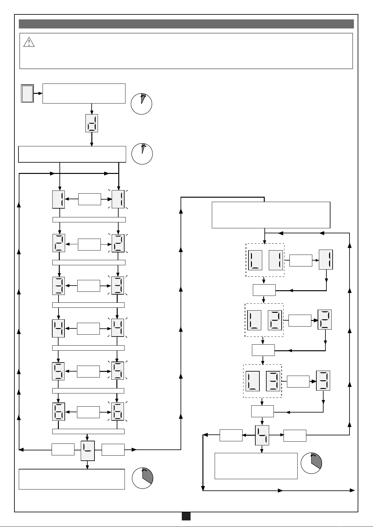
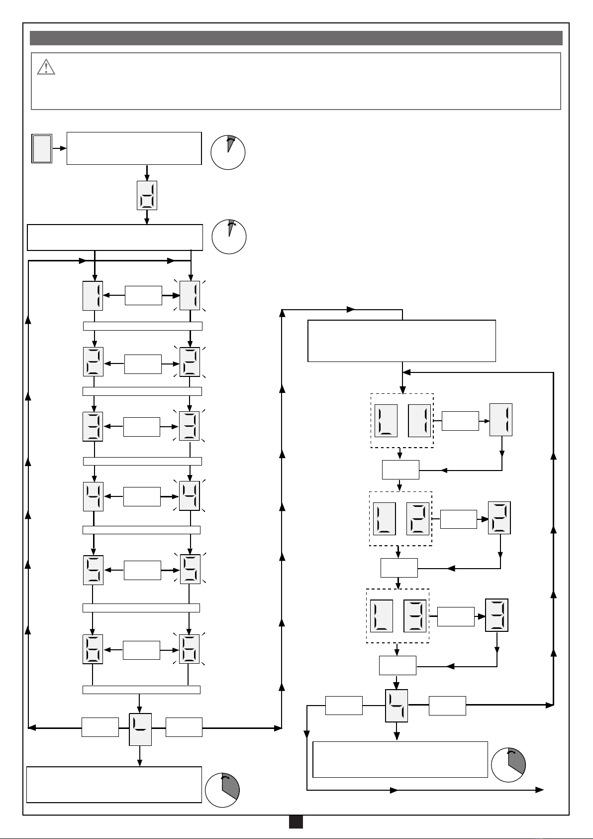
La programmazione, eseguibile mediante due soli pulsanti, permette la
configurazione del sensore di sforzo e del tempo di pausa. L’intervento
del sensore antischiacciamento/anticonvogliamento in fase di chiusura
causa l’inversione del moto e lo stesso avviene nella fase di apertura (se
la richiusura automatica è abilitata: in caso contrario causa solamente il
blocco). Se il moto è nella fase terminale, invece, il sensore agisce come
finecorsa amperometrico.
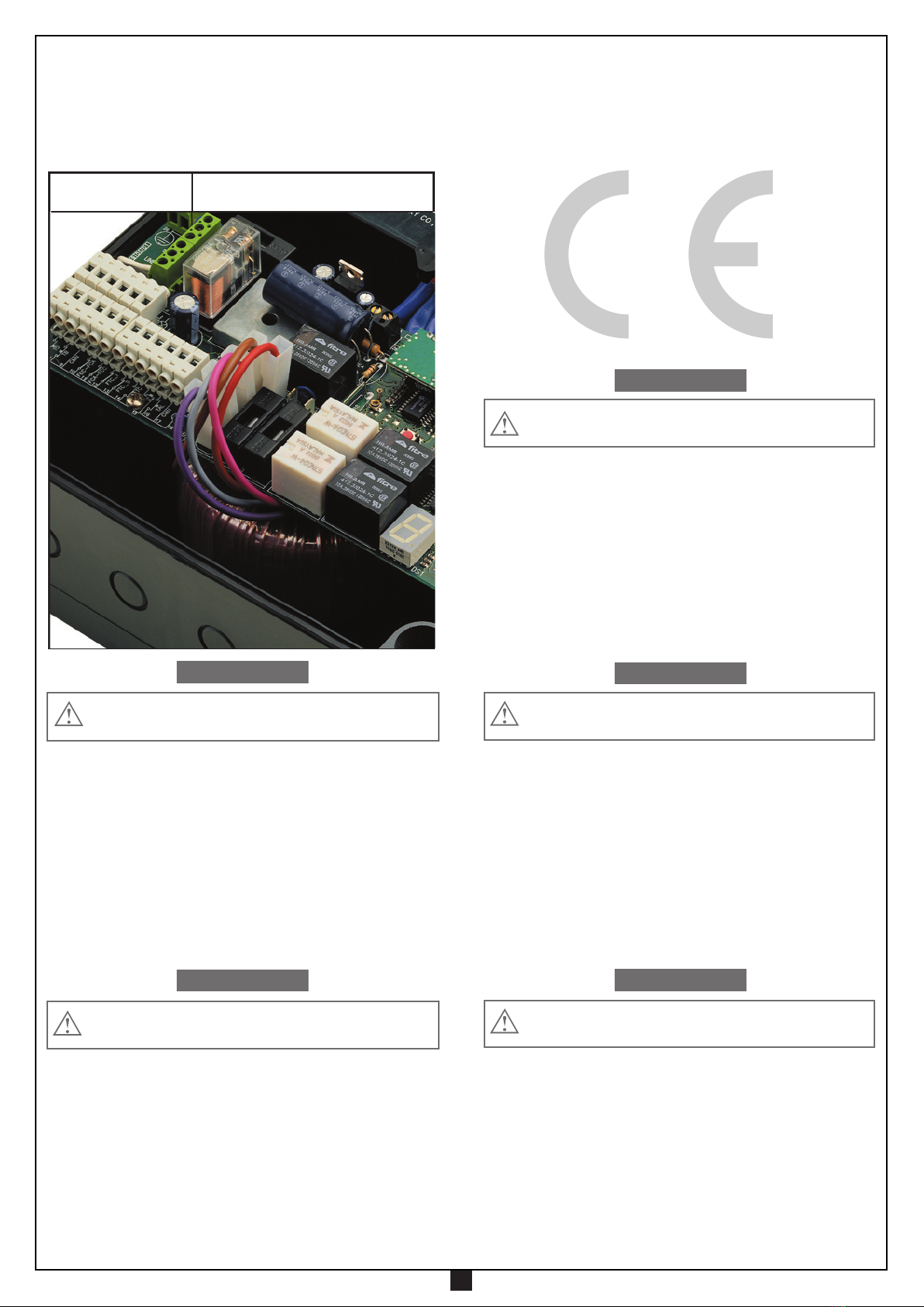
COLLEGAMENTO ELETTRICO
Aprire lo "Schema elettrico" piegato all'interno dell'ultima pagina del
presente libretto e procedere con la programmazione.
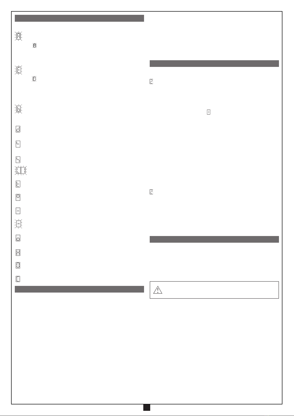
Legenda
B1 Buzzer segnalazione modalità "via radio"
D1 Display a 7 segmenti
F1 Fusibile 1,6A ritardato
(alimentazione 230Vac 50-60Hz)
F2 Fusibile 1A rapido (circuito 24V)
F3 Fusibile 10A rapido (alimentazione motore)
J2 Abilitazione alla memorizzazione via radio
(senza aprire il contenitore)
L1 LED di alimentazione scheda
L2 LED di gestione codici TX
L3 LED di modalità uomo presente
L4 LED di segnalazione fotocellule d'inversione
L5 LED di finecorsa apertura
L6 LED di finecorsa chiusura
L7 LED di segnalazione tasto di blocco
L8 LED di segnalazione fotocellule di blocco
M1 Modulo di memoria (300 codici)
P1 Tasto di programmazione
P2 Tasto di selezione
P3 Tasto di memorizzazione codice TX
P4 Tasto di cancellazione codice TX
R1 Modulo RF a 433.92 MHz
CN1 Connessione Faston secondario 24Vac
CN2 Connessione Faston secondario 20Vac
(V0:0Vac, V1:15Vac, V2:33Vac)
CN3 Connessione Faston motore
AVVERTENZE IMPORTANTI AVVERTENZE IMPORTANTI AVVERTENZE IMPORTANTI
PER RIDURRE IL RISCHIO DI FERITE GRAVI O MORTE, LEGGERE ATTENTAMENTE LE SEGUENTI
AVVERTENZE PRIMA DI PROCEDERE ALL’INSTALLAZIONE. PRESTARE PARTICOLARE ATTEN-
ZIONE A TUTTE LE SEGNALAZIONI DISPOSTE NEL TESTO. IL MANCATO RISPETTO
DI QUESTE POTREBBE COMPROMETTERE IL BUON FUNZIONAMENTO DEL SISTEMA.
Accertarsi, prima di eseguire il collegamento elettrico, che la
tensione e la frequenza riportate sulla targhetta caratteristiche
corrispondano a quelle dell'impianto di alimentazione.
Tra la centralina di comando e la rete deve essere interposto un
interruttore onnipolare, con distanza di apertura tra i contatti di
almeno 3 mm.
• Collegare i fili di comando e quelli provenienti dalle sicurezze.
• Collegare il cavo di alimentazione al dispositivo.
• Non utilizzare cavo con conduttori in alluminio; non stagnare l’estremità
dei cavi da inserire in morsettiera; utilizzare cavo con marcatura T min
85°C resistente agli agenti atmosferici.
• I conduttori dovranno essere adeguatamente fissati in prossimità della
morsettiera in modo che tale fissaggio serri sia l’isolamento che il con-
duttore (è sufficiente una fascetta).
Collegamenti morsettiera (pag. 28)
1-2-4-5 Comuni per tutti gli ingressi e uscite
3 Uscita 24 Vac 7W alimentazione dispositivi esterni
6 Uscita 24 Vac 10W lampeggiante (attivazione continua o
intermittente.)
7 TD (contatto N.A.) ingresso pulsante dinamico apre-chiude
8 TB(contattoN.C.) ingressopulsante di blocco(all'aperturadelcon-
tattosiinterrompeilciclodilavorofinoadunnuovocomandodimoto)
9-17 Comuni per tutti gli ingressi e uscite
10 FCC (contatto N.C.) ingresso finecorsa di chiusura
11 FCA (contatto N.C.) ingresso finecorsa di apertura
12 FTCI(contattoN.C.)ingresso perdispositividisicurezza(fotocellula
di inversione in chiusura). L'apertura del contatto, conseguente
all'interventodeidispositividisicurezza,durantela fasedichiusura,
attuerà l'inversione di moto.
13 FTCS (contatto N.C.) ingresso per dispositivi di sicurezza
(fotocellula di stop).
L'apertura del contatto blocca il moto; al
ritorno nella condizione di riposo, dopo il tempo di pausa il moto
riprenderà in chiusura (solo con richiusura automatica abilitata)
.
14 TC (contatto N.A.) ingresso pulsante di chiusura
15 TA (contatto N.A.) ingresso pulsante di apertura
16 TAL (contatto N.A.) ingresso pulsante di chiusura attivo al rila-
scio
18 Lampada spia 24 Vac 3W
19-20 Uscita 230 Vac 50-60Hz per trasformatore toroidale
21-22 Alimentazione programmatore 230 Vac 50-60Hz
23-24 Uscita 230 Vac 40W + 40W luce di cortesia
25 Terra per alimentazione programmatore
26 Uscita terra motore
27 Massa antenna ricevitore radio
28 Centrale antenna ricevitore radio (nel caso si utilizzi un'antenna
esterna collegarla con cavo coassiale RG58 imp. 50Ω)
N.B. TUTTI I CONTATTI N.C. NON UTILIZZATI VANNO PONTICELLATI
Alimentare il circuito e verificare che lo stato dei LED rossi di segnalazione
sia come segue:
- L1 LED di alimentazione circuito acceso
- L2 LED di programmazione codici trasmettitori spento
- L3 LED di segnalazione "uomo presente" spento
- L4 LED di sicurezza fotocellule d'inversione "FTCI" acceso
- L5 LED di finecorsa di apertura "FCA" acceso
- L6 LED di finecorsa di chiusura "FCC" acceso
- L7 LED di sicurezza tasto di blocco "TB" acceso
- L8 LED di sicurezza fotocellule di stop "FTCS" acceso
Verificare che l'attivazione delle sicurezze porti allo spegnimento del LED
ad esse associato.
Nel caso in cui il LED di alimentazione non si accenda verificare lo stato
dei fusibili ed il collegamento del cavo di alimentazione tra i morsetti "21"-
"22" (pag. 28).
Nel caso in cui uno o più LED di sicurezza non si accendano verificare i
contatti del relativo dispositivo di sicurezza collegato oppure controllare che
i contatti delle sicurezze non utilizzate siano ponticellati sulla morsettiera.
PROGRAMMATORE ELETTRONICO