User Manual
351CPGDSPRN, 351CPGDSPRL,
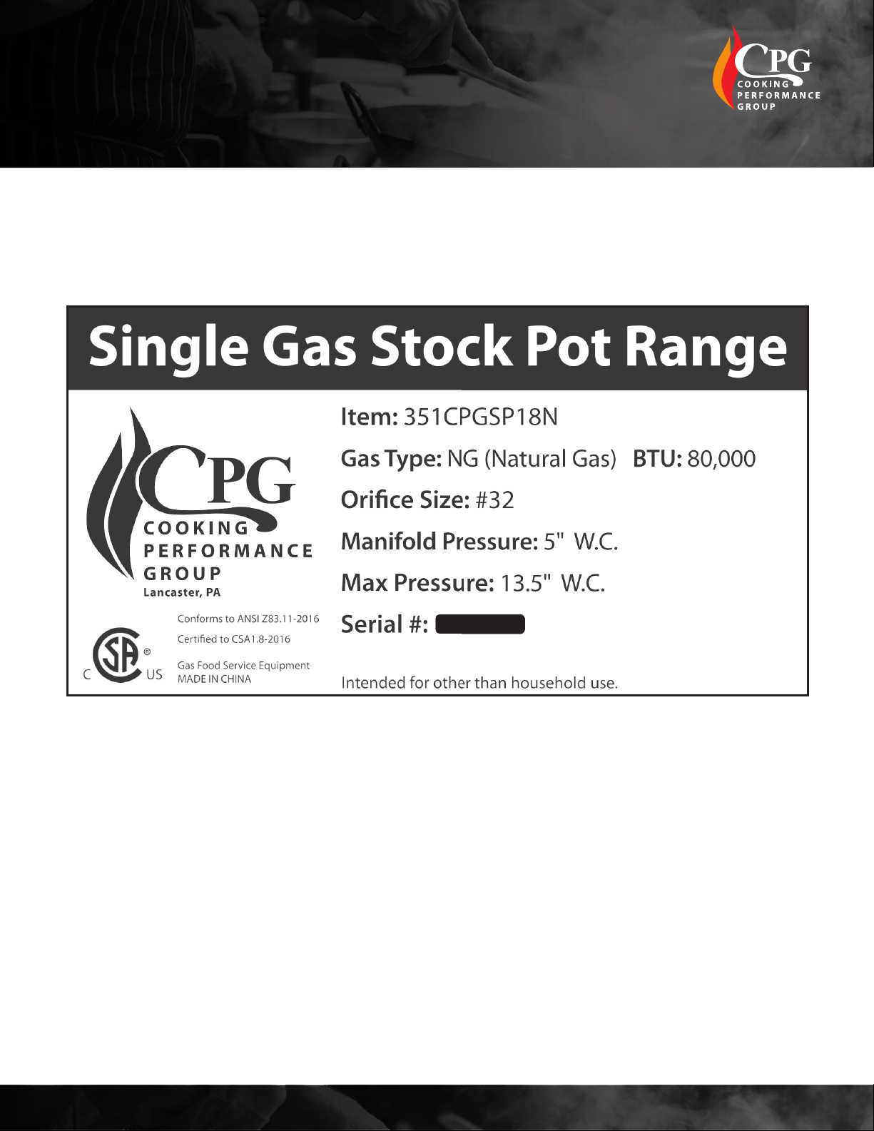
351CPGSP18N, 351CPGSP18L
www.cookingperformancegroup.com 7
GAS ELEVATION GUIDE AND GAS CONVERSION:
GAS CONVERSION:
Note: This installation is to be carried otut by a certied technician. Issues related to installation, such
as adjustments and calibrations, are the responsibility of the installer and are not matters of warranty.
Proof of installation may be required to make a warranty claim.
WARNING: Please allow sufcient time for the unit to cool down before converting to a new gas type.
1. Turn off range, remove all objects, and disconnect energy source
2. Remove control panel, cooking grates, pilot light head, and burner
3. Remove orice and replace with alternative gas type orice by screwing it in clockwise.
4. Reinstall burner, pilot light head, cooking grates, and control panel in proper order.
5. Have authorized technician adjust input appropriately.
EXHAUST SYSTEM:
1. The area in front of, around and above the appliance must be kept clear to avoid any obstruction of
the ow of combustion and ventilation air.
2. Adequate clearance must be maintained around the appliance for easy servicing.
3. Provisions should be made for any commercial, heavy duty cooking appliance to have it its exhaust
combustion waste products released to the outside of the building. The usual practice is to place the
appliance under an exhaust hood, which should be constructed in accordance with local codes.
4. Strong exhaust fans in this hood or in the overall air conditioning system can produce a slight
vacuum in the room and / or cause air drafts, either of which can interfere with the pilot or burner
performance and could be difcult to diagnose. Air movement should be checked during installation.
Air openings or bafes may have to be provided in the room, if pilot or burner outrage
problem persists.
5. Installation must conform with local codes, or in the absence of local codes, the National Fuel Gas
Code, ANS1 Z223.1 (latest edition). In Canada, installation should conform to installation codes for
gas burning appliances and equipment standard CAN/CGA-B149.1 or the propane installation code,
CAN/CGA-B149.2, as applicable.
MODEL Under 2,000ft 2,000-4,000ft 4,000-6,000ft 6,000-8,000ft 8,000-10,000ft
351CPGDSPRN #32 #33 #35 #36 #38
351CPGDSPRL #47 #48 #49 #50 #51
351CPGSP18N #32 #33 #35 #36 #38
351CPGSP18L #47 #48 #49 #50 #51
User Manual
351CPGDSPRN, 351CPGDSPRL,
351CPGSP18N, 351CPGSP18L