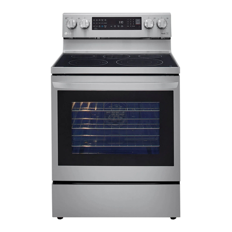
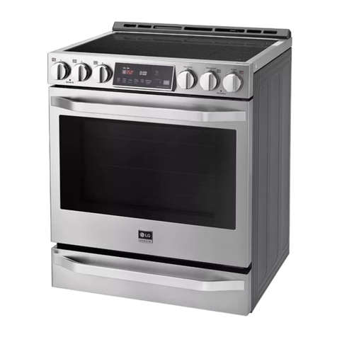
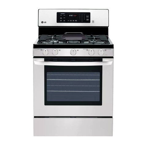
LG LRG30855S Series Installation guide

LG TRAINING MANUAL
LRG30855Sx Gas Range - Fall 2007
LG TRAINING MANUAL

GAS RANGE Page 1 of 72 TRAINING MANUAL
IMPORTANT SAFETY NOTICE
The information in this training manual is intended for use by persons possessing an adequate background
in electrical equipment, electronic devices, and mechanical systems. In any attempt to repair a major
appliance, personal injury and property damage can result. The manufacturer or seller maintains no liability
for the interpretation of this information, nor can it assume any liability in conjunction with its use. When
servicing this product, under no circumstances should the original design be modified or altered without
permission from LG Electronics. Unauthorized modifications will not only void the warranty, but may lead to
property damage or user injury. If wires, screws, clips, straps, nuts, or washers used to complete a ground
path are removed for service, they must be returned to their original positions and properly fastened.
CAUTION
To avoid personal injury, disconnect the power before servicing this product. If electrical power is required
for diagnosis or test purposes, disconnect the power immediately after performing the necessary checks.
Also be aware that many household appliances present a weight hazard. At least two people should be
involved in the installation or servicing of such devices. Failure to consider the weight of an appliance could
result in physical injury.
ESD NOTICE
Some of the electronics in appliances are electrostatic discharge (ESD) sensitive. ESD can weaken or
damage the electronics in these appliances in a manner that renders them inoperative or reduces the time
until their next failure. Connect an ESD wrist strap to a ground connection point or unpainted metal in the
appliance. Alternatively, you can touch your finger repeatedly to a ground connection point or unpainted
metal in the appliance. Before removing a replacement part from its package, touch the anti-static bag to a
ground connection point or unpainted metal in the appliance. Handle the electronic control assembly by its
edges only. When repackaging a failed electronic control assembly in an anti-static bag, observe these
same precautions.
REGULATORY INFORMATION
This equipment has been tested and found to comply with the limits for a Class B digital device, pursuant to
Part 15 of the FCC Rules. These limits are designed to provide reasonable protection against harmful
interference when the equipment is operated in a residential installation. This equipment generates, uses,
and can radiate radio frequency energy, and, if not installed and used in accordance with the instruction
manual, may cause harmful interference to radio communications. However, there is no guarantee that
interference will not occur in a particular installation. If this equipment does cause harmful interference to
radio or television reception, which can be determined by turning the equipment off and on, the user is
encouraged to try to correct the interference by one or more of the following measures: Reorient or relocate
the receiving antenna; Increase the separation between the equipment and the receiver; Connect the
equipment to an outlet on a different circuit than that to which the receiver is connected; or consult the
dealer or an experienced radio/TV technician for help.
DISCLAIMER
The information in this training manual was accurate at the time of publication. Every effort has been made
to ensure accuracy. Updates, changes, etc. are available via GCSC and LGCSacademy.
COMPLIANCE
The responsible party for this device’s compliance is LG Electronics Alabama, Inc.; 201 James Record Road,
Huntsville, AL, 35813.

GAS RANGE Page 2 of 72 TRAINING MANUAL
LRG30855** (GAS RANGE)
Safety Notices and Warnings 1
Contents 2
General Information 4
Introduction 5
Warranty 6
Installation 7
Anti-tip Device 8
Tools For Servicing 8
Operation 9
Surface Elements 9
Oven Vent 9
Other Controls 9
Touchpad Controls 10
Oven – Baking or Roasting 11
Oven – Broiling 11
Convection Baking or Roasting 12
Auto Recipe Conversion™ 12
Clock and Timer 12
Probe 13
Warming Drawer 13
Self-Cleaning Cycle 14
Component Location Views 15
Oven Door Removal and Replacement 18
Warming Drawer Removal and Replacement 19
Warming Drawer Element and Gasket 19
Gas Shutoff Valve 20
Main Top Removal 21
Side Panel Removal 21
Oven Hinge Removal 22
Door 23
Oven Light and Switch 24
Oven Burner Ignition 25
Broil Burner and ignitor 26
Bake Burner and Ignitor 27
Broil and Bake Burner Flame Adjustments 28
Bake and Broil Burner Test 28
Regulating Gas Pressure 29
Safety Valve and Pressure Regulator 30
Convection Fan Motor 31
Probe Outlet 32
Release 1.1 070822

GAS RANGE Page 3 of 72 TRAINING MANUAL
Oven Temperature Sensor 32
Control Panel 34
Spark Module 34
Electronic Range Control (ERC) 35
Control Panel and Touch Board 35
Surface Burner Assembly 36
Burner Removal 36
Main Burner Alignment 37
Maintop (Surface) Burner Flame Adjustments 37
Low Flame Simmer Adjustments 37
Testing Burner Flame Stability 38
Manifold Burner Valves 39
Ignitor Switches 40
Gas Manifold 41
Door Latch Assembly 42
Gas Conversion (Natural Gas vs. Propane or LP) 43
Convert The Surface Orifices (Spuds) 43
Convert The Bake and Broil Orifices 45
Check the Flame Quality 45
Oven Calibration 46
Lock Motor and Latch Circuit 47
Clean And Lock Sequence 48
Service Test Mode 49
Test Mode Chart 50
Failure Codes (F-Codes) 51
Key Panel Test 52
Warming Drawer Performance 52
Oven Self-Clean Operation 52
Convection Fan Operation 52
Parts List 53
Exploded View 60
Appendices 64
Installation Dimensions 64
Schematic and Wiring Diagrams 65
ERC (Electronic Range Control) Test Locations 67
Component Resistance Test Measurements 68
Component Voltage Test Measurements 69
Oven Sensor and Door Switch Test 70
Notes 72

GAS RANGE Page 4 of 72 TRAINING MANUAL
GENERAL INFORMATION
IMPORTANT SAFETY NOTICES
The information in this training manual is intended for use by persons who have
adequate backgrounds of electrical, electronic, and mechanical experience. Any
attempt to repair a major appliance may result in personal injury or property
damage. The manufacturer claims no responsibility for the interpretation of this
information not can it assume any liability in connection with its use.
If the information in this manual is not followed exactly, fire or explosion may
result, causing property damage, injury, or death. Gas (natural gas or propane) is
explosive.
If you smell gas:
•Do not try to light any appliance.
•Do not touch or operate any electrical switch.
•Do not use any phone (wired, portable, or cellular) in the building.
•Immediately call the gas supplier from a neighbor’s phone.
Follow the gas supplier’s instructions.
•If you can not contact the gas supplier, call the fire department.
To avoid personal injury, disconnect the power before servicing the appliance. If
electrical power is required diagnosis or testing, disconnect it immediately after
performing the necessary checks.
If grounding devices, wires, screws, straps, clips, nuts, or washers used to
complete a path to ground are removed for service, they must be replaced in
their original positions and properly secured.
This oven is not designed for open-door cooking.

GAS RANGE Page 5 of 72 TRAINING MANUAL
INTRODUCTION
The self-cleaning gas oven has a
tactile, electronic touchpad control. It
is user-friendly and easy to operate.
The surface burners are controller by
manually operated valves.
The convection baking and roasting
cycles provide even cooking and
superior baking results.
The nomenclature plate, with model
and serial numbers, is on the oven
frame above the warming drawer. This
plate also shows the burner ratings,
fuel type, and pressure settings from
the factory.
The mini-manual is in an envelope
taped behind the back panel.
The propane (LP Gas) instructions are
attached to the back of the range.
Inside, near the gas valve, is a set of
LP orifices for the conversion.
We recommend re-using this bracket
to save the natural gas orifices in the
event the range must be restored to
burn natural gas in the future.
The gas conversion should be
performed ONLY by a certified
gasfitter who has the proper training
and tools to accomplish the job.

GAS RANGE Page 6 of 72 TRAINING MANUAL
WARRANTY

GAS RANGE Page 7 of 72 TRAINING MANUAL
INSTALLATION
POWER SUPPLY
This appliance must be connected to 120 VAC, 60Ø current on a 20-amp,
dedicated circuit. Do not use an adapter or an ungrounded outlet.
GROUNDING SPECIFICATIONS
This appliance must be properly grounded. Wiring must conform to the National
Electrical Code (NEC) and all local codes.
Ground path resistance 0.10 W Max.
Insulation resistance 250 KW Min.
GAS SUPPLY
This range is designed to operate at a pressure of 5 inches of water column on
natural gas or 10 inches on LP (propane or butane).
MINIMUM CLEARANCES
This drawing shows the minimum
clearances for the gas range. The 30”
requirement between stovetop and
cabinet bottom allows sufficient space
to the installation of a standard over-
the-range microwave oven.
This drawing shows the dimensions
and suggested placement of the
electrical and gas connections behind
the range. The template makes it easy
to locate all items properly.
(See the larger drawing on page 64.)

GAS RANGE Page 8 of 72 TRAINING MANUAL
ANTI-TIP DEVICE
Be sure to install the anti-tip bracket.
This prevents tipping the range in the
event someone stands on the door or
otherwise puts the range off balance.
Use the installation template to locate
the wall bracket; then, attach the
bracket to the wall with a large wood
screw.
When the range is pushed back into
place, the bracket attached to the
range will be positioned under the wall
bracket and it will keep the range from
tipping.
TOOLS
For the most part, ordinary hand tools
are sufficient for installing the range.
It will be necessary to check the
incoming gas pressure and to
regulate it if it is out of specification.
A manometer is essential for proper
regulation of gas pressure and
diagnosis of supply and combustion
problems. You can use either a digital
manometer or the older style slack-
tube manometer.

GAS RANGE Page 9 of 72 TRAINING MANUAL
OPERATION
We include brief operating instructions for the technician to allow a thorough
check-out of the appliance and to use during diagnosis and repair.
SURFACE ELEMENTS
There are five surface elements, each of which is a different output. The controls
are all the same, though. Press the knob that corresponds to the element you
wish to operate and turn it counterclockwise (to the left) to the light position. You
will hear the tik-tik-tik of the igniter as it sparks to ignite the gas.
When the burner is lit, turn the knob to
the desired setting. Turn it clockwise to
the OFF position to extinguish the
flame. When one burner control is in
the IGNITE position, the igniters on all
the surface elements will fire. The
surface burners are controlled by
manual valves. These valves have a
low flame or simmer adjustment, which
will be covered later in this manual.
OVEN VENT
The oven is vented through ducts at the rear of the range top. Do not block these
vents while cooking in the oven. Because of the heat, do not leave closed
containers on the cooktop due to the burst hazard. Do not leave plastic or
flammable items on the cooktop; they may melt of ignite. Pot handles and
utensils will become very hot is left on the cooktop near the vent and could cause
burns.
OTHER CONTROLS
The gas oven, electric warming drawer,
convection, and self-cleaning functions
are operated from the electronic
touchpad control on the back of the
range.

GAS RANGE Page 10 of 72 TRAINING MANUAL
TOUCHPAD CONTROLS
1. PROBE – Press to select the
probe function.
2. BAKE – Press to select the
bake function.
3. BROIL HI/LO – Press to select
the broil function.
4. DISPLAY – Shows the time of
day, oven temperature, mode
bake, broil, convection or clean),
warming drawer, and others.
5. COOK TIME – Press, then enter
the cooking time. The oven will
stop when the time has elapsed.
6. DELAY START – Use with
COOK TIME or CELF CLEAN to
set a start time to cook or clean.
7. WARMING DRAWER – Press
this and number pads 1, 2, or 3
to turn on the warming drawer.
8. SELF CLEAN – Press to start a
self-cleaning cycle.
9. CONV BAKE – Press to select
convection baking.
10. CONV ROAST – Press to select
convection roasting.
11. CLOCK – Press, then use the
number pads to set the time.
12. TIMER ON/OFF – Press to use
the timer feature.
13. OVEN LIGHT – Turns the oven
light ON or OFF.
14. CLEAR/OFF – Press to cancel
any oven setting. It does not
affect the warming drawer,
clock, or timer.
15. NUMBER PADS – Press to
enter a number to a setting.
16. START – Press to start a
cooking, warming drawer, of
cleaning function.
A brief description of the controls and cycles follows to enable the technician to
test all the cycles and to verify that the repairs have been accomplished and the
range is now working to specification.

GAS RANGE Page 11 of 72 TRAINING MANUAL
OVEN – BAKING or ROASTING
This oven is not designed for open-door cooking. To operate the oven for regular
(non-convection) baking or roasting:
1. Touch BAKE
2. Touch the number pads to enter the desired temperature.
3. Touch START.
The display will show ON and 100° (or 40° if set for Celsius.) As the
oven heats, the display will show the changing temperature. When
the set point is reached, the buzzer will sound.
4. Touch CLEAR/OFF when cooking is complete.
OVEN – BROILING
This oven is not designed for open-door cooking. To operate the oven for regular
broiling:
1. Place the meat or fish on the broiler grid in the broiler pan.
2. Follow the suggestions for shelf positions in the Broiling Guide
(owner’s manual, page 15).
3. The oven door must be closed during broiling.
4. Touch BROIL HI/LO once for high or twice for low.
5. Touch START.
6. Touch CLEAR/OFF when broiling is complete.

GAS RANGE Page 12 of 72 TRAINING MANUAL
CONVECTION BAKING or ROASTING
The oven fan is turned off when the oven door is opened. Do not leave the door
open for long periods of time while using convection cooking. Since the oven is
not designed for any sort of open-door cooking, we recommend leaving the door
shut all the time other than when placing items in the oven or removing them.
1. Touch CONV BAKE or CONV ROAST.
2. Touch the number pads to set the desired temperature.
3. Touch START.
The display will show ON and 100° (or 40° if set for Celsius.) As the
oven heats, the display will show the changing temperature. When
the set point is reached, the buzzer will sound.
4. To change the oven temperature, touch CONV BAKE or CONV
ROAST and then touch the number pads to set the new desired
temperature.
5. Touch CLEAR/OFF when broiling is complete.
AUTO RECIPE CONVERSION™
When using the convection oven, it will automatically convert the temperatures
from regular baking to convection baking. No user intervention is necessary.
CLOCK and TIMER
1. Touch CLOCK.
2. Touch the number pads to enter the time. You must touch them in
the order they are read; for example, to enter a time of 10:54, you
must touch 1, 0, 5, and 4.
3. Touch and hold START until the time shows in the display.
4. To check the time while something else is showing on the display,
simply touch CLOCK.

GAS RANGE Page 13 of 72 TRAINING MANUAL
PROBE
The probe allows a reading of the internal temperature of the food during cooking.
Insert the probe into the food (typically a large roast or portion of meat) and plug
it in to the socket in the oven.
1. Insert the probe into the food.
2. Plug the probe into the socket inside the oven.
3. Touch PROBE.
4. Touch the number pads to set the desired internal temperature of
the food between 100° F (38° C) and 200° F (93° C).
5. Touch BAKE.
6. Touch the number pads to set the desired oven temperature.
7. Touch START.
8. When the internal temperature of the food reaches the setpoint, the
oven turns off and the buzzer sounds. To stop the buzzer, touch
CLEAR/OFF.
If the probe is removed from the food before the setpoint is reached, the buzzer
sounds and the display flashes until the probe is removed from the socket. You
can use the timer even though you cannot use timed oven functions while using
the probe.
To avoid damaging the probe, be certain the food is defrosted before inserting
the probe. It should not touch bone, fat, or gristle. When removing the probe, use
a hot pad rather than tongs to avoid damage. Never leave the probe in the oven
during a self-clean cycle.
WARMING DRAWER
The warming drawer uses a 500-watt, 110 VAC electric element.
Always start with hot food. Do not use the warming drawer to heat cold food.
Allow approximate 25 minutes for the warming drawer to preheat. Do not put
liquids, water, or aluminum foil in the warming drawer. The warming drawer
cannot be used during a self-cleaning cycle.

GAS RANGE Page 14 of 72 TRAINING MANUAL
To use the warming drawer:
1. Touch WARMING DRAWER.
2. Touch 1, 2, or 3on the number pad to select low, medium, or high.
3. Touch START.
4. To turn it off, touch WARMING DRAWER. Touching CLEAR/OFF
does nothing to the warming drawer.
SELF-CLEANING CYCLE
Before using the self-cleaning cycle, especially for the first time, we recommend
ventilating the kitchen with an open window or ventilation fan or hood. Remove
the broiler pan and grid, all cookware, all shelving and racking, and any trace of
aluminum foil.
Soils on the sealing surfaces of the door and the oven frame must be cleaned by
hand. Use hot water, a soap-filled scouring pad, or a cleanser like SoftScrub®.
Rinse well and dry thoroughly.
Do not attempt to clean the gasket. The fiberglass material cannot withstand
abrasion. It is essential for the gasket to remain intact. If you detect fraying or
wear, have the gasket replaced.
To set the oven for self cleaning:
1. Touch SELF CLEAN.
2. Use the number pads to set a clean time or go with the default
of 420 (four hours and twenty minutes.)
3. Touch START.
4. When the cycle is complete, the LOCKED light will extinguish and
the door will be unlocked.
If you set a self-clean cycle and forget to close the oven door, the display will
flash LOCKED. To stop a self-clean cycle, touch CLEAR/OFF. The LOCKED
light will extinguish and the door will unlock when the temperature has dropped to
a safe level.
After a self-clean cycle, there may be some white ash in the oven. This may be
wiped away with a damp cloth after the oven cools.

GAS RANGE Page 15 of 72 TRAINING MANUAL
COMPONENT LOCATION VIEWS

GAS RANGE Page 16 of 72 TRAINING MANUAL
COMPONENT LOCATION VIEWS

GAS RANGE Page 17 of 72 TRAINING MANUAL
COMPONENT LOCATION VIEWS
Control panel in service position
Cooktop removed, with heat shield and latch assembly cover removed

GAS RANGE Page 18 of 72 TRAINING MANUAL
OVEN DOOR REMOVAL
WARNING!
Sharp edges are exposed when
servicing the oven. Wear Kevlar®
gloves or an equivalent protective hand
cover.
OVEN DOOR REMOVAL
To remove the door, open it to the first
stop near the vertical (closed) position.
Lift the door and pull it straight up.
OVEN DOOR REPLACEMENT
Hold the door by the top corners in a
nearly vertical position (similar to
removal in the previous step.) Guide
the hinge arms into the door slots and
push the door onto the arms firmly.
Close the door and check for
alignment. Operate the door a couple
of times to make sure it opens and
closed properly and without binding.
If the door cannot be closed properly, it
is not seated on the hinge arms.

GAS RANGE Page 19 of 72 TRAINING MANUAL
WARMING DRAWER AND GASKET REPAIR
DRAWER REMOVAL
Pull the drawer out all the way to the
stop. There are tabs in the drawer rails.
Lift the left tab and push down the right
tab to pull the drawer off the rail.
DRAWER REPLACEMENT
To replace the drawer, place the rails
into the slides and push the drawer into
the range.
WARMING DRAWER TRACKS
Each track is attached to the range with
a Phillips screw and two tabs. To
remove the track, remove the screw
from the front of the track and pull the
slide out. Lift the track slightly and twist
it toward the center of the range to
disengage the front tab. Then pull the
track forward to release it.
WARMING DRAWER ELEMENT
Reminder! Unplug the range before
servicing the element! You’ll need to
remove the warming drawer to service
the heating element. Remove the two
T-15 Torx®screws that hold the
terminal cover. The element is attached
to the bottom of the range with six clips
held by ¼” hex-head screws.
WARMING DRAWER GASKET
The gasket is held by several small,
wire clips that are supplied already
formed into the gasket. Use needle-
nosed pliers to remove the clips. This
gasket forms a seal around the top and
sides of the drawer.
Table of contents
Other LG Range manuals
Popular Range manuals by other brands

Frigidaire
Frigidaire CGEF306TMFC installation instructions

Whirlpool
Whirlpool WEG750H0H owner's manual

GE
GE JB910SLSS - ProfileTM 30" Electric Range Dimensions and installation information

Electrolux
Electrolux EW30GF65G - 30'' Gas Range specification

Kenwood
Kenwood KDGC66S19 Installation instructions manual

Whirlpool
Whirlpool WERE4200PQ3 Assembly