CONTENTS
CONTENTS ...........................................................................................................................................................2
TABLE OF FIGURES ............................................................................................................................................... 4
1. GETTING STARTED......................................................................................................................................... 5
2. SAFETY..........................................................................................................................................................5
3. COMPONENTS INCLUDED WITH EMMA..........................................................................................................6
4. COMPONENTS THE INSTALLER NEEDS TO SUPPLY...........................................................................................7
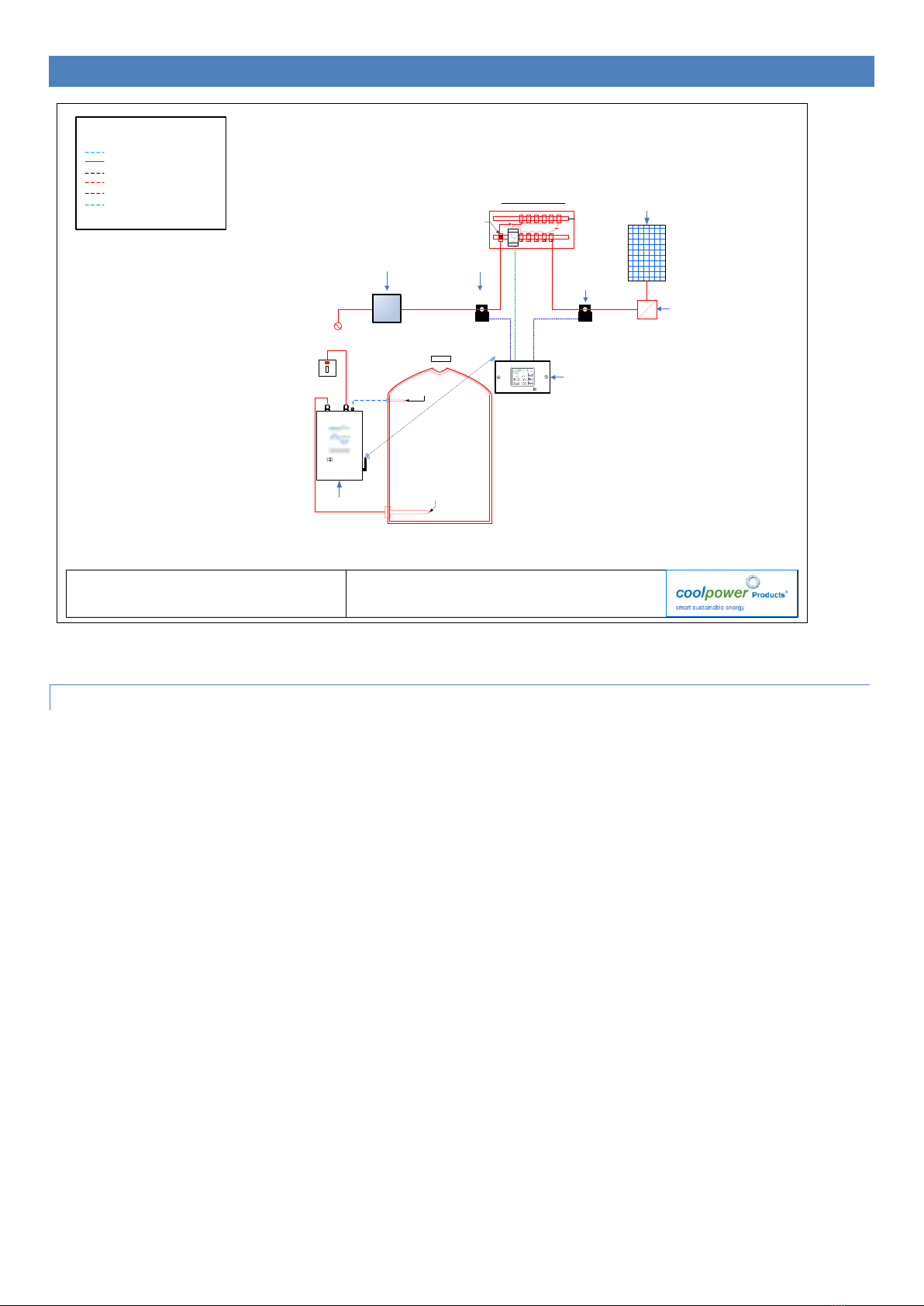
INSTALL OVERVIEW..............................................................................................................................................8
Description of basic operation................................................................................................................................... 8
5. ELITE INSTALLATION......................................................................................................................................9
ELITE WALL MOUNTING ...................................................................................................................................................... 9
Procedure................................................................................................................................................................... 9
CABLE ENTRIES .................................................................................................................................................................. 9
Procedure:.................................................................................................................................................................. 9
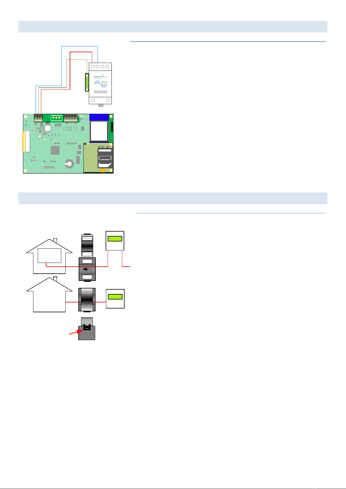
POWER SUPPLY TO THE ELITE ............................................................................................................................................... 9
Procedure................................................................................................................................................................... 9
POWER SUPPLY TO THE ELITE ............................................................................................................................................. 10
Procedure:................................................................................................................................................................10
FIT IMPORT EXPORT CT PROCEDURE ...................................................................................................................................10
Procedure:................................................................................................................................................................10
IMPORT EXPORT CT WIRING.............................................................................................................................................. 11
Procedure:................................................................................................................................................................11
FIT GENERATION CT.........................................................................................................................................................11
Procedure:................................................................................................................................................................11
GENERATION CT WIRING ..................................................................................................................................................11
Procedure................................................................................................................................................................. 11
CONNECT EARTH .............................................................................................................................................................12
Procedure................................................................................................................................................................. 12
ATTACH FACEPLATE TO BACKPLATE .....................................................................................................................................12
Procedure................................................................................................................................................................. 12
POWER THROTTLE INSTALLATION ...................................................................................................................... 13
POWER THROTTLE WALL MOUNTING ..................................................................................................................................13
Power Throttle Lid Screws........................................................................................................................................ 13
Power Throttle keyhole mounting slots ...................................................................................................................13
POWER THROTTLE MAINS WIRING ......................................................................................................................................14
POWER THROTTLE TEMP SENSOR WIRING.............................................................................................................................15
Extended Earth incoming lead with ring terminal termination to screw connection. .............................................15
Power Input from Mains ..........................................................................................................................................15
Power output to load...............................................................................................................................................15
TEMPERATURE SENSORS....................................................................................................................................................16