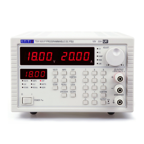
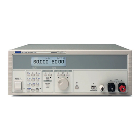
TTI TSX Series User manual

THURLBY THANDAR INSTRUMENTS
HIGH CURRENT DC POWER SUPPLIES
TSX SERIES
INSTRUCTION MANUAL

Table of Contents
Introduction 1
Specification 2
Safety 3
EMC 4
Installation 6
Operation 7
Maintenance and Repair 8
Instructions en Francais
Sécurité
Installation 10
Fonctionnement 11
Entretien et réparation 12
Bedienungsanleitung auf Deutsch
Sicherheit 13
Installation 14
Betrieb 15
Wartung und Instandsetzung 16
Istruzioni in Italiano
Sicurezza 17
Installazione 18
Funzionamento 19
Manutenzione 20
Instrucciones en Español
Seguridad 21
Instalación 22
Funcionamiento 23
Maintenimiento 24
Introduction
This series of bench power supplies offer high power outputs (in excess of 350 Watts) in a casing
which is both compact and lightweight when compared with conventional designs. Their high
performance is derived from a regulator design which combines switch-mode and linear
techniques to achieve high efficiency with excellent regulation, transient response and very low
noise.
The supplies feature high accuracy voltage and current metering on bright 0.5" LEDs, overvoltage
and thermal protection, and remote sense terminals. The output operates in constant voltage or
constant current mode with automatic crossover and mode indication. Coarse and fine controls
permit the output voltage to be set within 10 mV and the current limit control is logarithmic to give
good resolution at low current settings.
The supplies have a robust steel case which is half-rack width (3U height). They are Safety
Class I, Installation Category II instruments which meet EN61010-1 safety requirements and
comply with EN61326-1 EMC standard.
1

Specification
OUTPUT SPECIFICATIONS
Voltage Range: Nominally 0-35V (35V/10A), Nominally 0-18V (18V/20A)
Current Range: Nominally 0-10A (35V/10A), Nominally 0-20A (18V/20A)
Output Voltage Setting: By coarse and fine controls; 10mV setting resolution.
Output Current Setting: By single semi-logarithmic control; 10mA setting resolution.
Output Mode: Constant voltage or constant current with automatic crossover.
Output Switch: Electronic. Preset voltage and current displayed when off.
Output Terminals: 4mm terminals on front panel, screw terminals at rear.
Sensing: Remote via rear panel screw terminals or direct via shorting strip (supplied).
Output Impedance: <1mΩ in constant voltage mode.
>5kΩin constant current mode (voltage limit at max.).
Output Protection: Forward protection by Over-Voltage-Protection (OVP) trip; maximum voltage
that should be applied to the terminals is 50V.
Reverse protection by diode clamp for reverse currents up to 3A.
OVP Range: 10% to 110% of maximum output voltage set by front panel screwdriver
adjustment.
OVP Delay: <200µs
Load & Line Regulation: <0.01% of maximum output for 90% load change or 10% line change.
Ripple & Noise: <1mV rms typical in constant voltage
<3mA rms typical in constant current.
HF Common Mode
Noise:
Typically <3mV rms, <10mV peak.
Transient Response: 20µs to within 50mV of setting for 90% load change.
Temperature Coefficient: Typically <100 ppm/°C.
Protection Functions: Overvoltage trip. Regulator overtemperature. Sense miswiring.
Status Indication: Output off lamp. Constant voltage mode lamp
Constant current mode lamp. Trip message on display.
METER SPECIFICATIONS
Meter Types: Dual 4 digit meters with 12.5mm (0.5") LEDs. Reading rate 4Hz.
Meter Resolution: 10mV, 10mA
Meter Accuracy: Voltage 0.2% of reading ± 1 digit, current 0.5% of reading ± 1 digit.
GENERAL
AC Input Voltage: 110V-120V AC or 220V-240V AC ± 10%, 50/60Hz. Installation Category II.
Power Consumption: 600VA max.
Operating Range: 5°C to +40°C, 20% to 80% RH.
Storage Range: –40°C to +70°C.
Environmental: Indoor use at altitudes up to 2000m, Pollution Degree 2.
Size: 210 x 140 x 385mm (W x H x D), half rack width x 3U height
(optional rack mounting kit available)
Weight: 5kg.
Safety: Complies with EN61010-1
EMC: Complies with EN61326-1
2

Safety
This power supply is a Safety Class I instrument according to IEC classification and has been
designed to meet the requirements of EN61010-1 (Safety Requirements for Electrical Equipment
for Measurement, Control and Laboratory Use). It is an Installation Category II instrument
intended for operation from a normal single phase supply.
This instrument has been tested in accordance with EN61010-1 and has been supplied in a safe
condition. This instruction manual contains some information and warnings which have to be
followed by the user to ensure safe operation and to retain the instrument in a safe condition.
This instrument has been designed for indoor use in a Pollution Degree 2 environment in the
temperature range 5°C to 40°C, 20% - 80% RH (non-condensing). It may occasionally be
subjected to temperatures between +5°C and –10°C without degradation of its safety. Do not
operate while condensation is present.
Use of this instrument in a manner not specified by these instructions may impair the safety
protection provided. Do not operate the instrument outside its rated supply voltages or
environmental range.
WARNING! THIS INSTRUMENT MUST BE EARTHED
Any interruption of the mains earth conductor inside or outside the instrument will make the
instrument dangerous. Intentional interruption is prohibited. The protective action must not be
negated by the use of an extension cord without a protective conductor.
When the instrument is connected to its supply, terminals may be live and opening the covers or
removal of parts (except those to which access can be gained by hand) is likely to expose live
parts. The apparatus shall be disconnected from all voltage sources before it is opened for any
adjustment, replacement, maintenance or repair. Capacitors inside the power supply may still be
charged even if the power supply has been disconnected from all voltage sources but will be
safely discharged about 10 minutes after switching off power.
Any adjustment, maintenance and repair of the opened instrument under voltage shall be avoided
as far as possible and, if inevitable, shall be carried out only by a skilled person who is aware of
the hazard involved.
If the instrument is clearly defective, has been subject to mechanical damage, excessive moisture
or chemical corrosion the safety protection may be impaired and the apparatus should be
withdrawn from use and returned for checking and repair.
Make sure that only fuses with the required rated current and of the specified type are used for
replacement. The use of makeshift fuses and the short-circuiting of fuse holders is prohibited. Do
not wet the instrument when cleaning it.
The following symbols are used on the instrument and in this manual:-
Earth (ground) terminal.
mains supply OFF.
l mains supply ON.
alternating current (ac)
direct current (dc)
3

EC Declaration of Conformity
We Thurlby Thandar Instruments Ltd
Glebe Road
Huntingdon
Cambridgeshire PE29 7DR
England
declare that the following power supplies:
TSX3510, TSX1820
meet the intent of the EMC Directive 2004/108/EC and the Low Voltage Directive 2006/95/EC.
Compliance was demonstrated by conformance to the following specifications which have been
listed in the Official Journal of the European Communities.
EMC
Emissions: a) EN61326-1 (2006) Radiated, Class B
b) EN61326-1 (2006) Conducted, Class B
c) EN61326-1 (2006) Harmonics, referring to EN61000-3-2 (2006)
Immunity: EN61326-1 (2006) Immunity Table 1, referring to:
a) EN61000-4-2 (1995) Electrostatic Discharge
b) EN61000-4-3 (2006) Electromagnetic Field
c) EN61000-4-11 (2004) Voltage Interrupt
d) EN61000-4-4 (2004) Fast Transient
e) EN61000-4-5 (2006) Surge
f) EN61000-4-6 (2007) Conducted RF
Performance levels achieved are detailed in the user manual.
Safety
EN61010-1 Installation Category II, Pollution Degree 2.
CHRIS WILDING
TECHNICAL DIRECTOR
1 May 2009
4

EMC
This instrument has been designed to meet the requirements of the EMC Directive 2004/108/EC.
Compliance was demonstrated by meeting the test limits of the following standards:
Emissions
EN61326-1 (2006) EMC product standard for Electrical Equipment for Measurement, Control and
Laboratory Use. Test limits used were:
a) Radiated: Class B
b) Conducted: Class B
c) Harmonics: EN61000-3-2 (2006) Class A; the instrument is Class A by product category.
Immunity
EN61326-1 (2006) EMC product standard for Electrical Equipment for Measurement, Control and
Laboratory Use.
Test methods, limits and performance achieved are shown below (requirement shown in
brackets):
a) EN61000-4-2 (1995) Electrostatic Discharge : 4kV air, 4kV contact, Performance A (B).
b) EN61000-4-3 (2006) Electromagnetic Field:
3V/m, 80% AM at 1kHz, 80MHz – 1GHz: Performance A (A) and 1.4GHz to 2GHz:
Performance A (A); 1V/m, 2.0GHz to 2.7GHz: Performance A (A).
c) EN61000-4-11 (2004) Voltage Interrupt: ½ cycle and 1 cycle, 0%: Performance A (B);
25 cycles, 70%: Performance A (C); 250 cycles, 0%: Performance B (C).
d) EN61000-4-4 (2004) Fast Transient, 1kV peak (AC line), 0·5kV peak (signal connections),
Performance A (B).
e) EN61000-4-5 (2006) Surge, 0·5kV (line to line), 1kV (line to ground), Performance A (B).
f) EN61000-4-6 (2007) Conducted RF, 3V, 80% AM at 1kHz (AC line only; signal
connections <3m, therefore not tested), Performance A (A).
According to EN61326-1 the definitions of performance criteria are:
Performance criterion A: ‘During test normal performance within the specification limits.’
Performance criterion B: ‘During test, temporary degradation, or loss of function or
performance which is self-recovering’.
Performance criterion C: ‘During test, temporary degradation, or loss of function or
performance which requires operator intervention or system reset occurs.’
Cautions
To ensure continued compliance with the EMC directive observe the following precautions:
a) Connect the generator to other equipment using only high quality, double−screened cables.
b) After opening the case for any reason ensure that all signal and ground connections are
remade correctly and that case screws are correctly refitted and tightened.
c) In the event of part replacement becoming necessary, only use components of an identical
type, see the Service Manual.
5

Installation
Mains Operating Voltage
Check that the instrument operating voltage marked on the rear panel is suitable for the local
supply. Should it be necessary to change the operating voltage, proceed as follows:
1. Ensure that the instrument is disconnected from the AC supply.
2. Remove the 6 screws holding the case upper and lift off the cover.
3. Change the appropriate zero-ohm links beside the transformer on the pcb:
Link LK5 only for 230V operation
Link LK1 and LK3 only for 115V operation
4. Re-assemble in the reverse order.
5. To comply with safety standard requirements the operating voltage on the rear panel must be
changed to clearly show the new voltage setting.
Mains Lead
When a three core mains lead with bare ends is provided this should be connected as follows:
BROWN - MAINS LIVE
BLUE - MAINS NEUTRAL
GREEN/YELLOW - EARTH
SafetyEarthSymbol
When fitting a fused plug a 5 amp fuse should be fitted inside the plug. As the colours of the
wires in the mains lead of this apparatus may not correspond with the coloured markings
identifying the terminals in your plug proceed as follows:
The wire which is coloured green-and-yellow must be connected to the terminal in the plug which
is marked by the letter E or by the safety earth symbol shown above or coloured green or green-
and-yellow.
The wire which is coloured blue must be connected to the terminal which is marked with the letter
N or coloured black.
The wire which is coloured brown must be connected to the terminal which is marked with the
letter L or coloured red.
WARNING! THIS APPARATUS MUST BE EARTHED.
Any interruption of the protective conductor inside or outside the apparatus or disconnection of
the protective earth terminal is likely to make the apparatus dangerous. Intentional interruption is
prohibited.
6

Operation
Output Setting
With the POWER switch on (l) and the OUTPUT push-button switch off (out) the output voltage
and current limit can be accurately set using the three output controls; the left-hand meter
indicates set voltage and the right-hand meter set current.
When the OUTPUT is switched on, the ON LED and the CV (constant voltage) LED will light; the
left-hand meter continues to show the set voltage but the right-hand meter now shows actual
current drawn. Alternate presses of the I METER DAMPING button will switch current meter
damping in and out; with damping switched in the DAMPED LED will be lit and the average value
of a varying load current will be read.
If the output goes into current limit the CI (constant current) LED will light instead of the CV LED
and the left-hand meter will now show the actual voltage at the output terminals; the right-hand
meter will continue to show the set current limit.
At any time, the set voltage and set current levels can be reviewed by pressing the CHECK V/I
button.
Outputs from several supplies may be connected in series or parallel to produce higher voltages
or higher currents respectively. Care must be taken when connecting supplies in series to ensure
that the maximum voltage rating of any output terminal (300V peak maximum with respect to true
ground) is not exceeded.
Connection to the Load
Connection to the front panel output terminals can be made with 4mm plugs, spade terminals or
wire ends. To minimise voltage drop, the connecting leads to the load should be of an adequate
wire gauge and be kept short. Load wires should also be twisted together to minimise
inductance.
To overcome errors introduced by connecting lead resistance at higher currents the remote
sensing facility should be used (10 mΩof lead resistance will drop 0.2 Volt at 20 Amps). Remove
the two shorting links made between the rear output and sense terminals and connect the sense
terminals directly to the load; the power connections may be made from either the front or the
rear terminals.
To ensure good coupling between the output and sense, the sense wires should be twisted with
their corresponding output leads before the output leads are twisted together.
The voltage drop in each output lead must not exceed 1 Volt.
The shorting links should be re-made between the rear sense and output terminals when remote
sensing is not being used. However, the sense connection is also made internally through a low
value resistor and only a small error between the set and actual voltage will result if the links are
left disconnected.
The output is fully floating and either terminal can be connected to ground or raised by up to
300V peak above true ground; however, such voltages are hazardous and great care should be
taken.
The current limit control can be set to limit the continuous output current to levels down to 10mA.
However, in common with all precision bench power supplies, a capacitor is connected across the
output to maintain stability and good transient response. This capacitor charges to the output
voltage, and short circuiting of the output will produce a short current pulse as the capacitor
discharges which is independent of the current limit setting.
7

Protection
Overvoltage protection (OVP) is fully variable within the range 10% to 110% of the supply's
maximum output level. The OVP limit is set via the screwdriver adjustable SET OVP preset
potentiometer, accessible through a hole in the front panel. Rotating the preset clockwise
increases the limit, which can be read directly on the left-hand display by pressing the READ
OVP button. If the voltage on the output exceeds the set OVP for any reason, including an
externally forced voltage, the output will be tripped off.
The output will also be tripped off if the thermal sensing detects overheating of any of the power
semiconductors, or if the sense wires are wired to the wrong output or if an attempt is made to
draw power from the sense wires.
In all the above cases, the 'TRIP' message will be shown in both displays. Once the cause of the
trip has been removed, normal operation can be restored by switching the POWER switch off ( )
then on (l) again.
The output is protected from reverse voltages by a diode; the continuous reverse current must not
exceed 3 Amps, although transients can be much higher.
Ventilation
These instruments are very efficient but nevertheless can generate significant heat at full power.
The supplies rely on convection cooling only and it is therefore important that ventilation is never
restricted if performance and safety are to be maintained. If the supplies are mounted in a
restricted space, eg. a 19 inch rack, then adequate ventilation must be ensured by using, for
example, a fan tray.
Maintenance and Repair
The Manufacturers or their agents overseas will provide repair for any unit developing a fault.
Where owners wish to undertake their own maintenance work, this should only be done by skilled
personnel in conjunction with the service manual which may be purchased directly from the
Manufacturers or their agents overseas.
Fuse
The correct fuse type for all models and AC supply ranges is:
10 Amp 250V HBC time-lag, 5 x 20 mm
Make sure that only fuses with the required rated current and of the specified type are used for
replacement. The use of makeshift fuses and the short-circuiting of fuse-holders is prohibited.
To replace the fuse, first disconnect the instrument from the AC supply. Remove the 6 cover
securing screws and lift off the cover. Replace the fuse with one of the correct type and refit the
cover.
Note that the main function of the fuse is to make the instrument safe and limit damage in the
event of failure of one of the switching devices. If a fuse fails it is therefore very likely that the
replacement will also blow, because the supply has developed a fault; in such circumstances the
instrument will need to be returned to the manufacturer for service.
Cleaning
If the PSU requires cleaning use a cloth that is only lightly dampened with water or a mild
detergent. Polish the display window with a soft dry cloth.
WARNING! TO AVOID ELECTRIC SHOCK, OR DAMAGE TO THE PSU, NEVER ALLOW
WATER TO GET INSIDE THE CASE. TO AVOID DAMAGE TO THE CASE OR DISPLAY
WINDOW NEVER CLEAN WITH SOLVENTS.
8

Sécurité
Ce système alimentation est un instrument de classe de sécurité 1 conforme à la classification
IEC et il a été conçu pour satisfaire aux exigences de la norme EN61010-1 (Exigences de
sécurité pour les équipements électriques de mesure, de contrôle et d'utilisation en laboratoire). Il
s'agit d'un instrument de Catégorie II d'installation devant être exploité depuis une alimentation
monophasée standard.
Cet instrument a été testé conformément à la norme EN61010-1 et il a été fourni en tout état de
sécurité. Ce manuel d'instructions contient des informations et des avertissements qui doivent
être suivis par l'utilisateur afin d'assurer un fonctionnement et un état en toute sécurité.
Cet instrument a été conçu pour être utilisé en intérieur, en environnement de pollution de
deuxième degré (Pollution degree 2) à des plages de températures de 5°C à 40°C, et à des taux
d'humidité compris entre 20% et 80% (sans condensation). Il peut être soumis de temps à autre à
des températures comprises entre +5°C et –10°C sans dégradation de sa sécurité. Ne pas
l'utiliser en conditions de condensation.
Toute utilisation de cet instrument de manière non spécifiée par ces instructions risque d'affecter
sa protection de sécurité. Ne pas utiliser l'instrument hors des plages de tension d'alimentation
nominale recommandées ni hors de ses tolérances d'environnement.
AVERTISSEMENT ! CET INSTRUMENT DOIT ETRE RELIE A LA TERRE
Toute interruption du conducteur de la terre du secteur à l'intérieur ou à l'extérieur de l'instrument
rendra l'instrument dangereux. Il est absolument interdit de priver intentionnellement l'instrument
de son branchement à la terre. La sécurité de l'instrument ne doit pas être annulée par l'utilisation
de rallonge sans conducteur de protection.
Lorsque l'instrument est relié au secteur, il est possible que les bornes soient sous tension :
l'ouverture des couvercles ou la dépose de pièces (à l'exception des pièces accessibles
manuellement) risque de mettre à découvert des pièces sous tension. L'instrument doit être
débranché du secteur et de toute source d'alimentation avant tout réglage, remplacement,
travaux d'entretien ou de réparations.
Les condensateurs qui se trouvent dans le bloc d'alimentation risquent de rester chargés, même
si le bloc d'alimentation a été déconnecté de toutes les sources d'alimentation, mais ils se
déchargeront en toute sécurité environ 10 minutes après extinction de l'alimentation.
Eviter dans la mesure du possible d'effectuer des réglages, travaux de réparations ou d'entretien
lorsque l'instrument ouvert est branché au secteur. Si cela s'avère toutefois indispensable, seul
un technicien compétent connaissant les risques encourus doit effectuer ce genre de travaux.
S'il est évident que l'instrument est défectueux, qu'il a été soumis à des dégâts mécaniques, à
une humidité excessive ou à une corrosion chimique, la protection de sécurité est affaiblie :
l'instrument doit être retiré de l'exploitation et renvoyé vérifications et de réparations.
Ne remplacer les fusibles que par des fusibles d'intensité nominale requise et du type spécifié. Il
est interdit d'utiliser des fusibles "maison" et de court-circuiter des porte-fusibles.
Ne jamais humidifier l'instrument lors du nettoyage.
Les symboles suivants se trouvent sur l'instrument, ainsi que dans ce manuel.
Borne de terre (masse)
l alimentation secteur ON (allumée) courant continu (c.c.)
alimentation secteur OFF (éteinte) courant alternatif (c.a.)
9

Installation
Tension de fonctionnement
Vérifier que la tension de fonctionnement de l'instrument indiquée sur le panneau arrière convient
à l'alimentation locale. S'il s'avère nécessaire de la modifier, procéder comme suit :
1. S'assurer que l'instrument est débranché de l'alimentation c.a.
2. Retirer les 6 vis qui maintiennent le couvercle du boîtier et démonter celui-ci en le
soulevant.
3. Changer les liaisons zéro-Ohm appropriées de la carte à circuits imprimés, située à côté
du transformateur:
Relier LK5 pour la seule alimentation à 230 V
Relier LK1 et LK3 pour la seule alimentation à 115 V
4. Effectuer le remontage dans l'ordre inverse.
5. Afin de respecter les impératifs des normes de sécurité, modifier l'indication de tension de
fonctionnement sur le panneau arrière, pour indiquer clairement la nouvelle tension
d'alimentation.
Câble secteur
Lorsqu'un câble secteur à trois conducteurs et aux extrémités dénudées est fourni, il doit être
branché comme suit :
MARRON - SECTEUR-TENSION
BLEU - SECTEUR-NEUTRE
VERT/JAUNE - TERRE Symbole de prise de terre de sécurité
Lors de l'installation d'une prise à fusible, un fusible de 5 ampères doit être utilisé. Les couleurs
des fils du câble secteur de cet appareil ne correspondant pas forcément aux couleurs utilisées
pour identifier les bornes de la prise, aussi il est recommandé de suivre la procédure ci-dessous :
Le fil vert et jaune doit être connecté à la borne de la prise près de laquelle figure la lettre E ou le
symbole de terre ci-dessus ou de couleur verte ou verte/jaune.
Le fil bleu doit être connecté à la prise de la borne près de laquelle figure la lettre N ou de couleur
noire.
Le fil marron doit être connecté à la borne près de laquelle figure la lettre L ou de couleur rouge.
ATTENTION ! CET APPAREIL DOIT ETRE RELIE A LA TERRE
Toute interruption du conducteur de la terre du secteur à l'intérieur ou à l'extérieur de l'instrument
rendra l'instrument dangereux. Il est absolument interdit de priver intentionnellement l'instrument
de son branchement à la terre.
10

Fonctionnement
Réglage de la sortie
Lorsque l'interrupteur POWER (Alimentation) est sur ON (actif) et que le bouton OUTPUT (sortie)
est relâché (inactif) la tension de sortie et la limite de courant peuvent être réglées avec précision
à l'aide des trois commandes de sortie ; l'affichage de gauche indique la tension et l'affichage de
droite indique le courant appliqué.
Lorsque le bouton OUTPUT est enfoncé (actif) , la DEL ON et la DEL CV (Constant Voltage -
tension constante) s'allument ; l'affichage de gauche continue d'indiquer la tension appliquée,
tandis que l'affichage de droite indique maintenant le courant réellement utilisé. Le fait d'enfoncer
puis de relâcher le bouton I METER DAMPING active puis inhibe l'amortissement de
l'ampèremètre ; lorsque l'amortissement est actif, la DEL DAMPED s'allume et la valeur moyenne
d'un courant de charge variable s'affiche.
Si la puissance de sortie passe dans la limite de courant, la DEL CI s'allume au lieu de la DEL
CV, et l'affichage de gauche indique la tension réelle aux bornes de sortie ; l'affichage de droite
continue d'indiquer la limite de courant appliquée.
A tout moment, la tension et le courant appliqués peuvent être contrôlés en appuyant sur le
bouton CHECK V/I.
Les sorties de plusieurs sources peuvent être connectées en série ou en parallèle afin de
produire respectivement des tensions ou des courants plus élevés. Il convient de s'assurer, lors
du branchement d'appareils en série, que la tension nominale maximale de toute borne de sortie
(crête de 300 V maximum par rapport à la masse réelle) n'est pas dépassée.
Connexion à la charge
La connexion aux bornes de sortie du panneau avant peut s'effectuer à l'aide de prises de 4 mm,
des cosses ou des extrémités de fils. Pour minimiser la chute de tension, les fils de connexion à
la charge doivent être des fils de calibre suffisant et doivent rester courts. Les fils de charge
doivent être torsadés ensemble pour minimiser l'inductance.
Pour prévenir les erreurs introduites par la connexion d'une résistance à des courants plus
élevés, le dispositif de télédétection doit être utilisé (10 mΩde résistance de fil cause une de
baisse de 0,2 Volt à 20 A). Retirer les deux contacts court-circuitants entre la sortie arrière et les
bornes de détection et connecter les bornes de détection directement à la charge ; les
connexions d'alimentation peuvent s'effectuer des bornes avant ou arrière.
Pour assurer le branchement correct entre la sortie et la borne de détection, les fils de détection
doivent être torsadés ensemble avec leurs fils de sortie respectifs avant de torsader ensemble
les fils de sortie.
La chute de tension de chaque fil de sortie ne doit pas dépasser 1 Volt.
Les contacts court-circuitants doivent être rétablis entre les bornes arrière de détection et de
sortie lorsque la télédétection n'est pas utilisée. Cependant, la connexion de la borne de
détection se fait également de l'intérieur par le biais d'une résistance de faible valeur, et seule
une erreur mineure entre la tension appliquée et la tension réelle en résulte si les contacts ne
sont pas branchés.
La sortie est isolée de la terre et l'une ou l'autre des bornes peut être reliée à la terre ou
augmentée de 300 V maximum au-dessus de la masse réelle ; cependant, ces tensions sont
dangereuses et il une extrême prudence s'impose.
La commande de limite de courant peut être appliquée pour limiter le courant de sortie continu à
des niveaux aussi faibles que 10 mA. Toutefois, comme pour toutes les sources d'alimentation de
précision, un condensateur est connecté en parallèle à la sortie, afin de maintenir la stabilité et
une bonne réponse transitoire. Ce condensateur transfère la charge à la tension de sortie, et
lorsque le condensateur se décharge, un court-circuit de la sortie produit une courte impulsion de
courant, indépendante de la limite de courant adoptée.
11

Protection
La protection contre les surtensions est entièrement variable dans la plage de 10% à 110% du
niveau maximal d'alimentation en sortie. Cette limite s'applique à l'aide du potentiomètre préréglé
SET OVP réglable par tournevis et accessible par une ouverture dans le panneau frontal. Tourner
le potentiomètre en sens horaire pour augmenter la limite. Cette limite s'affiche sur le compteur
de gauche par pression sur le bouton READ OVP (Lire la surtension). Si la tension de la sortie
dépasse la protection de surtension appliquée, pour quelque raison que ce soit, y compris une
tension externe forcée, la sortie disjoncte.
La sortie disjoncte également si le détecteur thermique rélève une surchauffe de l'un des semi-
conducteurs, si les fils de détection sont connectés à la mauvaise sortie ou en cas de tentative de
prélèvement d'alimentation des fils de détection.
Dans tous ces cas, le message TRIP (Interruption) s'affiche sur les deux affichages. Une fois la
raison de l'interruption éliminée, le fonctionnement normal peut reprendre en plaçant l'interrupteur
POWER alternativement sur ( ) puis (l).
La sortie est protégée des tensions inverses par une diode ; le courant inverse continu ne doit
pas dépasser 3 A, bien que les courants transitoires puissent être beaucoup plus importants.
Ventilation
Ces appareils sont extrêmement efficaces, mais ils peuvent néanmoins générer une chaleur
importante à plein régime. Les appareils ne sont refroidis que par convection. Il est donc
important, pour garantir les performances et la sécurité, de s'assurer que la ventilation ne soit
jamais gênée. Si les appareils sont installés dans un espace réduit, tel qu'un châssis de 19
pouces, une ventilation adéquate doit être assurée, par l'utilisation, par exemple, de ventilateurs.
Entretien et réparation
Le constructeur ou ses agents à l'étranger répareront toute unité qui tombe en panne. Si le
propriétaire de l'appareil décide d'effectuer ses propres réparations, celles-ci doivent être
effectuées exclusivement par un personnel spécialisé qui doit se référer au manuel de
maintenance disponible directement auprès du constructeur ou de ses agents à l'étranger.
Fusible
Le fusible qui convient pour tous les modèles et toutes les plages de CA est :
10 Amp 250V HBC à action retardée, 5 x 20 mm
S'assurer que seuls les fusibles du courant nominal et du type spécifiés sont utilisés. Il est interdit
d'utiliser des fusibles "maison" ou de court-circuiter les porte-fusibles.
Pour remplacer le fusible, débrancher tout d'abord l'instrument de la source d'alimentation CA.
Retirer les 6 vis de fixation du couvercle et déposer ce dernier. Remplacer le fusible par un
fusible approprié puis remettre le couvercle en place.
Il convient de noter que la fonction principale d'un fusible est d'assurer la sécurité de l'appareil, et
de limiter les dégâts en cas de panne de l'un des dispositifs de commutation.
Si un fusible saute il est donc très probable que le fusible de remplacement sautera aussi, en
raison d'une défectuosité dans l'alimentation ; dans ce cas l'instrument devra être renvoyé au
constructeur pour réparation.
Nettoyage
S'il faut nettoyer le bloc d'alimentation, utiliser un chiffon légèrement imbibé d'eau ou d'un
détergent doux. Nettoyer le cadran d'affichage au moyen d'un chiffon sec et doux.
AVERTISSEMENT ! EMPECHER TOUTE INTRODUCTION D'EAU DANS LE BOITIER AFIN
D'EVITER TOUT CHOC ELECTRIQUE ET DEGATS AU BLOC D'ALIMENTATION. NE JAMAIS
UTILISER DE SOLVANTS POUR NETTOYER LE BLOC, AFIN D'EVITER D'ENDOMMAGER LE
BOITIER OU LE CADRAN D'AFFICHAGE.
12

Sicherheit
Diese Stromversorgung wurde nach der Sicherheitsklasse (Schutzart) I der IEC-Klassifikation und
gemäß den europäischen Vorschriften EN61010-1 (Sicherheitsvorschriften für Elektrische Meß-,
Steuer, Regel- und Laboranlagen) entwickelt. Es handelt sich um ein Gerät der
Installationskategorie II, das für den Betrieb von einer normalen einphasigen Versorgung
vorgesehen ist.
Das Gerät wurde gemäß den Vorschriften EN61010-1 geprüft und wurde in sicherem Zustand
geliefert. Die vorliegende Anleitung enthält vom Benutzer zu beachtende Informationen und
Warnungen, die den sicheren Betrieb und den sicheren Zustand des Gerätes gewährleisten.
Dieses Gerät ist für den Betrieb in Innenräumen der Umgebungsklass 2 , für einen
Temperaturbereich von 5° C bis 40° C und 20 - 80 % relative Feuchtigkeit (nicht kondensierend)
vorgesehen. Gelegentlich kann es Temperaturen zwischen +5° und –10°C ausgesetzt sein, ohne
daß seine Sicherheit dadurch beeinträchtigt wird. Betreiben Sie das Gerät jedoch auf keinen Fall,
solange Kondensation vorhanden ist.
Ein Einsatz dieses Geräts in einer Weise, die für diese Anlage nicht vorgesehen ist, kann die
vorgesehene Sicherheit beeinträchtigen. Auf keinen Fall das Gerät außerhalb der angegebenen
Nennversorgungsspannungen oder Umgebungsbedingungen betreiben.
WARNUNG! - DIESES GERÄT MUSS GEERDET WERDEN!
Jede Unterbrechung des Netzschutzleiters innerhalb oder außerhalb des Geräts macht das Gerät
gefährlich. Eine absichtliche Unterbrechung ist verboten. Die Schutzwirkung darf durch
Verwendung eines Verlängerungskabels ohne Schutzleiter nicht aufgehoben werden.
Ist das Gerät an die elektrische Versorgung angeschlossen, so können die Klemmen unter
Spannung stehen, was bedeutet, daß beim Entfernen von Verkleidungs- oder sonstigen Teilen
(mit Ausnahme der Teile, zu denen Zugang mit der Hand möglich ist) höchstwahrscheinlich
spannungsführende Teile bloßgelegt weden. Vor jeglichem Öffnen des Geräts zu Nachstell-,
Auswechsel-, Wartungs- oder Reparaturzwecken, Gerät stets von sämtlichen Spannungsquellen
abklemmen. Kondensatoren in der Stromversorgung können auch noch nach Abschalten
sämtlicher Stromversorgung Spannung führen, sie entladen sich jedoch innerhalb von etwa 10
Minuten nach Spannungsabschaltung.
Jegliche Nachstellung, Wartung und Reparatur am geöffneten, unter Spannung stehenden Gerät,
ist nach Möglichkeit zu vermeiden. Falls unvermeidlich, sollten solche Arbeiten nur von
qualifiziertem Personal ausgeführt werden, das sich der Gefahren bewußt ist.
Ist das Gerät eindeutig fehlberbehaftet, bzw. wurde es mechanisch beschädigt, übermäßiger
Feuchtigkeit oder chemischer Korrosion ausgesetzt, so können die Schutzeinrichtungen
beeinträchtigt sein, weshalb das Gerät aus dem Verkehr zurückgezogen und zur Überprüfung
und Reparatur eingesandt werden sollte.
Sicherstellen, daß nur Sicherungen der vorgeschriebenen Stromstärke und des vorgesehenen
Typs als Ersatz verwendet werden. Provisorische “Sicherungen” und der Kurzschluß von
Sicherungshaltern ist verboten.
Beim Reinigen darauf achten, daß das Gerät nicht naß wird.
Am Gerät werden folgende Symbole verwendet:
Erdungsklemme
l Netz ON (ein) Gleichstrom
Netz OFF (aus) Wechselstrom
13

Installation
Netzbetriebspannung
Sicherstellen, dass die auf der Geräterückwand angegebene Betriebsspannung mit der
Versorgungsspannung am Ort übereinstimmt. Falls es erforderlich ist, die Betriebsspannung zu
ändern, wie folgt vorgehen:
1. Sicherstellen, dass das Gerät vom Wechselstromnetz getrennt ist.
2. Die 6 Schrauben entfernen, mit denen die obere Gehäusehälfte befestigt ist, und den
Deckel abheben.
3 Die in Frage kommenden Null-Ohm-Drahtbrücken neben dem Transformator auf der
Platine nach Bedarf umstecken.
Drahtbrücke LK5 nur für 230 V-Betrieb
Drahtbrücke LK1 und LK3 nur für 115 V-Betrieb
4. Gerät in umgekehrter Reihenfolge wieder zusammenbauen.
5. Die Sicherheitsvorschriften werden nur dann erfüllt, wenn auch die Angabe der
Betriebsspannung auf der Geräterückwand geändert wird, so dass die neue
Spannungseinstellung deutlich angezeigt ist.
Netzanschlußkabel
Ein mitgeliefertes dreiadriges Anschlußkabel mit abisolierten Enden ist wie folgt anzuschließen:
BRAUN - STROMFÜHREND
BLAU - NEUTRAL
GRÜN/GELB - ERDE Schutzerdesymbol
Beim Anbau eines abgesicherten Steckers ist eine 5 A Sicherung im Stecker anzubringen. Da die
Farben der Adern im Netzkabel des Geräts unter Umständen nicht mit den Farben der
Steckerklemmen übereinstimmen, wie folgt vorgehen:
Die grün/gelbe Ader ist an die Steckerklemme anzuschließen, die mit dem Buchstaben E, dem
oben angegebenen Schutzerdesymbol oder grün oder grün/gelber Farbe versehen ist.
Die blaue Ader ist mit der Klemme zu verbinden, die mit dem Buchstaben N oder schwarzer
Farbe gekennzeichnet ist.
Die braune Ader ist mit der Klemme zu verbinden, die mit dem Buchstaben L oder roter Farbe
gekennzeichnet ist.
WARNUNG! DIESES GERÄT MUSS GEERDET WERDEN.
Jegliche Unterbrechung des Schutzleiters innerhalb oder außerhalb des Geräts oder ein
Abschließen des Schutzleiteranschlusses kann dazu führen, daß das Gerät gefährlich wird. Eine
absichtliche Unterbrechung ist unzulässig.
14

Betrieb
Ausgangseinstellung
Bei eingeschaltetem LEISTUNGSSCHALTER (l) und ausgeschaltetem AUSGANGS-
DRUCKSCHALTER ist es möglich, mit Hilfe der drei Ausgangsverstellungen die
Ausgangsspannung und Strombegrenzung genau einzustellen. Die linke Anzeige läßt die
Spannung, die rechte die Stromstärke erkennen.
Nach dem Einschalten des AUSGABESCHALTERS leuchten die Netz-LED und die CV-LED
(konstante Spannung). Die linke Anzeige zeigt weiterhin die eingestellte Spannung; auf der
rechten Anzeige erscheint jetzt jedoch der aufgenommene Iststrom. Durch Drücken der Taste I
METER DAMPING (ANZEIGEDÄMPFUNG) wird die Dämpfung der Stromanzeige ein- und
ausgeschaltet. Während des Einschaltens leuchtet die Lampe DAMPED (GEDÄMPFT) und auf
der Anzeige erscheint der Mittelwert der schwankenden Stromaufnahme.
Wenn die Ausgabe auf Strombegrenzung geht, leuchtet die Lampe CI (konstanter Strom) anstelle
der Lampe CV und auf der linken Anzeige erscheint jetzt die Istspannung an den
Ausgangsklemmen. Auf der rechten Anzeige erscheint weiterhin die eingestellte
Strombegrenzung. Durch Drücken der Taste CHECK V/I (PRÜFUNG V/I) können jederzeit
Sollspannung und Sollstrombegrenzung angezeigt werden.
Die Ausgänge verschiedener Stromversorgungen können in Reihe oder parallel geschaltet
werden, um höhere Spannungen oder höhere Stromstärken zu erzeugen. Bei einer
Reihenschaltung der Versorgungsquellen ist darauf zu achten, daß die max. Nennspannung
irgendeiner Ausgangsklemme nicht überschritten wird (Spitzenspannung 300 V gegen Erde).
Anschluß des Verbrauchers
Der Anschluß an die Ausgangsklemmen der Fronttafel kann durch Stecker 4 mm, Flachstecker
oder Drahtenden durchgeführt werden. Um den Spannungsabfall zu minimieren, müssen die
Anschlußkabel der Verbraucher einen ausreichenden Querschnitt haben und kurz gehalten
werden. Verbraucherdrähte sind zu verdrallen, um die Selbstinduktion zu mindern.
Um Fehler durch den Leitungswiderstand bei größeren Stromstärken zu vermeiden, ist die
Fernerfassungseinrichtung zu verwenden (10 mΩLeitungswiderstand führt zu einem Abfall von
0,2 V bei 20 A). Die beiden kurzen Brücken zwischen den hinteren Ausgangs- und
Erfassungsklemmen entfernen und die Erfassungsklemmen direkt mit dem Verbraucher
verbinden. Die Leistungsanschlüsse können an die vorderen oder hinteren Klemmen angelegt
werden.
Um eine gute Verbindung zwischen Ausgang und Abtastung herzustellen, sind die Abtastdrähte
mit den entsprechenden Ausgangsleitungen zu verdrallen, bevor die Ausgangsleitungen
zusammen verdrallt werden. Der Spannungsabfall in jeder Ausgangsleitung darf 1 V nicht
überschreiten. Wird die Fernerfassung nicht mehr verwendet, müssen die Brücken zwischen den
hinteen Erfassungs- und Ausgangsklemmen wieder eingesetzt werden. Der Abtastanschluß wird
jedoch auch intern über einen niedrigohmigen Widerstand hergestellt, und ohne Einsatz der
Brücken entsteht nur ein kleiner Fehler zwischen Soll- und Istspannung.
Der Ausgang ist vollständig ungeerdet, und jede Klemme kann an Erde angeschlossen oder mit
einer Spitzenspannung von 300 V gegen Erde erhoben werden. Derartige Spannungen sind
jedoch gefährlich und erfordern große Vorsicht.
Mit Hilfe der Strombegrenzungsverstellung kann der Ausgangsstrom bis herunter auf eine Höhe
von 10 mA begrenzt werden. Wie jedoch in allen Präzisionsstromversorgungseinheiten ist ein
Kondensator über dem Ausgang vorgesehen, um Stabilität und gutes Einschwingverhalten zu
gewährleisten. Dieser Kondensator wird durch die Ausgangsspannung geladen, und ein
Kurzschluß der Ausgangsspannung erzeugt einen kurzen Stromimpuls während des Entladens
des Kondensators; dieser ist unabhängig von der Einstellung der Strombegrenzung.
15

Schutz
Der Überspannungsschutz ist im Bereich von 10 % bis 110 % der höchsten
Versorgungsspannung einstellbar. Die Einstellung erfolgt durch Schraubendreher mit Hilfe des
Potentiometers SET OVP (ÜBERSPANNUNGSSCHUTZ EINSTELLEN), der durch ein Loch in
der Frontplatte zugänglich ist. Durch ein Drehen im Uhrzeigersinn (nach rechts) wird die Grenze
vermindert. Nach Drücken der Taste READ OVP (ÜBERSPANNUNGSSCHUTZ LESEN)
erscheint die Begrenzung direkt auf der linken Anzeige. Sollte die Ausgangsspannung den
eingestellten Überspannungsschutz aus irgendeinem Grunde oder durch eine externe Spannung
überschreiten, wird der Ausgang abgeschaltet.
Das Abschalten des Ausgangs erfolgt ebenfalls, wenn ein Thermistor die Übertemperatur eines
Leistungshalbleiters erkennt, wenn die Abtastdrähte mit dem falschen Ausgang verbunden sind
oder wenn es versucht wird, den Verbraucher an die Abtastleitungen anzuschließen.
Unter allen obigen Bedingungen erscheint die Meldung “TRIP” (AUSGELÖST) auf beiden
Anzeigen. Nachdem der Grund für die Auslösung entfernt wurde, kann der normale Betrieb nach
dem AUS- ( ) und EINSCHALTEN (l) des Leistungsschalters fortgesetzt werden. Eine Diode
schützt den Ausgang im Fall von Gegenspannungen. Ein kontinuierlicher Gegenstrom darf 3 A
nicht überschreiten, obgleich gelegentliche Spitzen viel höher liegen können.
Belüftung
Diese Geräte sind besonders leistungsvoll, können jedoch bei Volleistung eine erhebliche Wärme
erzeugen. Das Stromversorgungsgerät wird nur durch Konvektion gekühlt, deshalb darf die
Belüftung niemals behindert werden, um eine hohe Leistung und Sicherheit zu erhalten. Wenn
das Stromversorgungsgerät in beschränktem Raum angeordnet ist, z.B. einem 19" Gestell, muß
für ausreichende Belüftung zum Beispiel durch Verwendung eines Fremdlüfters gesorgt werden.
Wartung und Instandsetzung
Die Hersteller bzw. deren Vertretungen im Ausland bieten die Instandsetzung von Geräten an, bei
denen eine Störung aufgetreten ist. Wenn der Eigentümer die Wartungsarbeiten selbst
durchfuhren möchte, hat er dafür Sorge zu tragen, daß diese Arbeiten ausschließlich von
entsprechend qualifiziertem Personal und gemäß den Vorgaben im Wartungshandbuch
ausgeführt werden, das direkt bei den Herstellern oder deren Vertretungen im Ausland bezogen
werden kann.
Sicherung
Die korrekte Sicherung für alle Modelle und Wechselstrombereiche ist:
10 A, 250V, träge HBC Sicherung, 5 x 20 mm
Bitte darauf achten, daß nur Sicherungen mit der richtigen Amperezahl und des angegebenen
Typs zum Auswechseln verwendet werden. Der Gebrauch von provisorischen Sicherungen und
das Kurzschließen von Sicherungshaltern ist verboten.
Zum Ersatz der Sicherung zunächst das Gerät von der Netzversorgung abschließen. Sechs
Befestigungsschrauben am Deckel abschrauben und Deckel abheben. Die Sicherung gegen eine
der korrekten Art austauschen und Deckel wieder anbauen.
Es ist zu beachten, daß es die Hauptfunktion der Sicherung ist, das Gerät zu schützen und beim
Ausfall einer Schalteinrichtung jeglichen Schaden zu begrenzen. Wenn deshalb eine Sicherung
durchbrennt, brennt sehr wahrscheinlich auch die Ersatzsicherung durch, da ein Fehler in der
Versorgung vorliegt. Unter diesen Umständen ist das Gerät den Herstellern zwecks Wartung
einzusenden.
Reinigung
Falls die Stromversorgung der Reinigung bedarf, eine mit Wasser oder einem milden Detergens
angefeuchteten Lappen benutzen. Anzeigefenster mit einem weichen, trockenen Lappen
polieren.
WARNUNG! ZUR VERMEIDUNG EINES ELEKTRISCHEN SCHLAGS BZW. BESCHÄDIGUNG DER
STROMVERSORGUNGSEINHEIT, DAFÜR SORGEN, DASS KEIN WASSER INS GEHÄUSE
EINDRINGT. UM SCHADEN AM GEHÄUSE BZW. AM ANZEIGEFENSTER ZU VERMEIDEN, KEINE
LÖSUNGSMITTEL ZUR REINIGUNG VERWENDEN!
16

Sicurezza
Questo alimentatore appartiene alla Categoria di Sicurezza 1 secondo la classifica IEC ed è stato
progettato in modo da soddisfare i criteri EN61010-1 (requisiti di Sicurezza per Apparecchiature
di misura, controllo e per uso in laboratorio). È uno strumento di Categoria II di installazione e
inteso per funzionamento con un’alimentazione normale monofase.
Questo strumento ha superato le prove previste da EN61010-1 e viene fornito in uno stato di
sicurezza normale. Questo manuale contiene informazioni e avvertenze che devono essere
seguite per assicurarsi di un’operazione sicura e mantenere lo strumento in condizioni di
sicurezza.
Questo strumento è progettato per uso all’interno e in un ambiente d’inquinamento Grado 2, entro
la gamma di temperatura da 5°C a 40°C con umidità relativa (non condensante) di
20% - 80%. Può occasionalmente essere assoggettato a temperature fra +5°C e –10°C senza
comprometterne la sicurezza. Non usare in presenza di condensazione.
L’uso dello strumento in maniera non conforme a quanto specificato in queste istruzioni potrebbe
pregiudicare la protezione di cui è dotato. Non usare lo strumento per misurare tensioni al di
sopra dei valori nominali o in condizioni ambientali al di fuori di quelle specificate.
ATTENZIONE! QUESTO STRUMENTO DEVE ESSERE COLLEGATO A TERRA
Una qualsiasi interruzione sia interna che esterna del collegamento a terra lo rende pericoloso. È
proibito interrompere questo collegamento deliberatamente. La protezione non deve essere
negata attraverso l’uso di un cavo di prolunga privo del filo di collegamento a terra.
Quando lo strumento è alimentato, alcuni morsetti sono sotto tensione e l’apertura dei coperchi o
la rimozione di parti (eccetto quei componenti accessibili senza l’uso di attrezzi) può lasciare
scoperti dei morsetti sotto tensione. L’apparecchiatura deve essere staccata da tutte le sorgenti
di tensione prima di aprirla per regolazioni, manutenzione o riparazioni.
I condensatori collegati all’alimentazione interna possono essere carichi anche dopo aver
staccato l’alimentazione ma si scaricano in circa 10 minuti dopo aver levato la corrente.
È consigliabile evitare, per quanto possibile, qualsiasi operazione di regolazione e di riparazione
dello strumento sotto tensione e, qualora fosse inevitabile, dette operazioni devono essere
eseguite da una persona specializzata in materia, che sia pienamente conscia del pericolo
presente.
Quando sia chiaro che lo strumento è difettoso, o che ha subito un danno meccanico, un eccesso
di umidità, o corrosione a mezzo di agenti chimici, la sicurezza potrebbe essere stata
compromessa e lo strumento deve essere ritirato dall’uso e rimandato indietro per le prove e le
riparazioni del caso.
Assicurarsi di usare solo fusibili della portata giusta e del tipo corretto durante eventuali
sostituzioni. Sono proibiti sia l’uso di fusibili improvvisati che il corto circuito deliberato dei
portavalvole.
Non bagnare lo strumento quando si pulisce.
Sullo strumento e in questo manuale si fa uso dei seguenti simboli.
Terminale di Terra
lalimentazione ON (accesa) Corrente Continua
alimentazione OFF (spenta)
Corrente Alternata
17

Installazione
Tensione d’esercizio
Controllare che la tensione d’esercizio dello strumento segnata sul pannello posteriore sia uguale
a quella della rete elettrica locale. Se dovesse rendersi necessario cambiare la tensione
d'esercizio, osservare il seguente procedimento:
1. Controllare che lo strumento sia scollegato dall'alimentazione a c.a.
2. Rimuovere le 6 viti che tengono la parte superiore del corpo e sollevare il coperchio.
3. Cambiare il collegamento vicino al trasformatore sul circuito stampato:
Collegare soltanto LK5 per tensione d’esercizio di 230V.
Collegare solo LK1 e LK3 per tensione d’esercizio di 115V.
4. Riassemblare invertendo la procedura di smontaggio.
5. Per soddisfare le norme di antinfortunistica, la tensione segnata sul pannello posteriore deve
essere opportunamente modificata per mostrare chiaramente la nuova impostazione di
tensione.
Cavo d’Alimentazione
Quando viene fornito un cavo tripolare ad estremità scoperte per il collegamento a rete, questo
dovrebbe essere connesso nel modo seguente:
MARRONE - RETE FASE
BLU - RETENEUTRO
VERDE/GIALLO - TERR
Simbolo di Sicurezza di Terra
Quando si monta una spina con fusibile, un fusibile a 5 amp dovrebbe essere inserito nella spina.
Dato che i colori dei fili nel cavo di collegamente a rete di questo apparecchio potrebbero non
corrispondere ai segni colorati che identificano i morsetti nella vostra presa, procedete come
segue:
Il filo di colore verde e giallo deve essere connesso al morsetto nella presa che è marchiato con
la lettera E o con il simbolo della terra mostrato sopra o di colore verde o verde e giallo.
Il filo di colore blu deve essere connesso al morsetto marchiato con la lettera N o di colore nero.
Il filo di colore marrone deve essere connesso al morsetto marchiato con la lettera L o di colore
rosso.
AVVERTENZA! QUESTO APPARECCHIO DEVE ESSERE MESSO A TERRA.
Qualsiasi interruzione del conduttore all'interno o all'esterno dell'apparecchio o sconnessione del
morsetto protettivo della terra può verosimilmente rendere l'apparecchio pericoloso. L'interruzione
intenzionale è proibita.
18

Funzionamento
Regolazione dell'Output [Livello d'Uscita].
Quando l’interruttore POWER [alimentazione] è acceso e il pulsante OUTPUT [livello d'uscita] è
spento, il voltaggio d'uscita e il limite della corrente possono venire regolati accuratamente
usando i tre controlli dell'uscita: il contatore sulla sinistra indica il voltaggio e quello sulla destra la
corrente prescelti.
Quando l'OUTPUT è acceso, il LED ON e il LED CV (voltaggio costante) si accendono; il
contatore sulla sinistra continua a mostrare il voltaggio scelto ma il contatore sulla destra mostra
ora la reale corrente ricevuta. Premendo alternativamente il tasto I METER DAMPING [lettura
fissa del contatore I] si attiverà e disattiverà la lettura fissa del contatore di corrente; con la lettura
fissa attivata il DAMPED LED [fissato] sarà acceso e il valore medio di un carico di corrente
variabile verrà letto.
Se il livello d'uscita rientra nel limite di corrente il LED CI (corrente costante) si accenderà invece
del LED CV ed il contatore sulla sinistra mostrerà ora il valore reale del voltaggio che arriva ai
morsetti d'uscita; il contatore sulla destra continuerà a mostrare il limite di corrente fissato. Il
voltaggio e il livello di corrente prescelti possono venire rivisti schiacciando il tasto CHECK V/I
[controllo V/I]. Delle uscite da diversi alimentatori possono venire connesse in serie o in parallelo
per produrre rispettivamente dei voltaggi più alti o delle correnti più alte. Quando si connettono
degli alimentatori in serie ci si deve assicurare che il valore massimo di voltaggio di ogni morsetto
d'uscita (300 V picco massimo rispetto alla massa reale) non venga superato.
Connessione al Carico
La connessione con i morsetti d'uscita del pannello frontale può essere eseguita con degli spinotti
da 4 mm, dei terminali a lancia o con le estremità dei fili. Per ridurre al minimo la caduta di
voltaggio, i cavi di connessione al carico dovrebbero essere di diametro adeguato e dovrebbero
essere tenuti corti. I cavi di carico dovrebbero inoltre essere intrecciati fra di loro per ridurre al
minimo l'induttanza.
Per superare delle malfunzioni provocate dalla connessione della resistenza del cavo a delle
correnti più alte si dovrebbe usare la funzione di rilevamento a distanza (10 mΩdi resistenza del
cavo faranno perdere 0,2 Volt a 20 amp). Rimuovete i due contatti di corto fra i morsetti dell'uscita
e i morsetti di rilevamento sul retro e collegate i morsetti del rilevamento direttamente al carico; le
connessioni di potenza possono essere fatte sia dai morsetti frontali che da quelli posteriori.
Per assicurare un buon accoppiamento fra l'uscita e il rilevamento, i cavi del rilevamento
dovrebbero venire intrecciati con i loro corrispondenti cavi dell'uscita prima che i cavi dell'uscita
siano intrecciati assieme. La perdita di voltaggio in ogni singolo cavo d'uscita non deve superare
1 Volt.
I collegamenti di corto fra i morsetti del rilevamento sul retro ed i morsetti dell'uscita devono
venire rifatti quando il controllo a distanza non viene più usato. In ogni caso, la connessione del
rilevamento è anche fatta internamente all'apparecchio tramite una resistenza di basso valore e
solo un piccolo errore risulterà fra il voltaggio prescelto e quello reale se i contatti vengono
lasciati sconnessi.
L'uscita è completamente fluttuante ed uno qualsiasi dei due morsetti può essere messo a massa
o alzato di un valore fino a 300 V di picco al di sopra della massa reale; comunque tali voltaggi
sono pericolosi e si deve usare grande cautela.
Il controllo del limite della corrente può venire regolato in modo tale da limitare il flusso continuo
della corrente d'uscita a dei livelli minimi fino a 10 mA. Comunque, come per tutte le alimentazioni
da banco di precisione, un condensatore è connesso trasversalmente all'uscita per mantenere la
stabilità ed una buona risposta ai transistori. Questo condensatore si carica al voltaggio d'uscita,
ed un corto circuito dell'uscita produrrà un breve impulso di corrente mentre il condensatore si
scarica, il quale è indipendente dai valori fissati del limite della corrente.
19
Other manuals for TSX Series
2
Table of contents
Other TTI Power Supply manuals
