Cooper & Hunter CHV5 Series User manual

Service manual
CHV5 Mini DC INVERTER VRF UNITS
Thank you for choosing Cooper&Hunter VRF CHV5, please read this service manual carefully
before operation and retain it for future reference.
CHV5 Mini DC INVERTER
VRF UNITS
Models:
CHV-5S120NK2
CHV-5S140NK2
CHV-5S160NK2
CHV-5S120NM2
CHV-5S140NM2
CHV-5S160NM2

CONTENTS
PRODUCT ........................................................................................................................................ 1
1 PRODUCT LIST ........................................................................................................................................ 1
2 NOMENCLATURE..................................................................................................................................... 2
2.1 Nomenclature of outdoor units.................................................................................................................. 2
3 PRODUCT FEATURES............................................................................................................................. 2
3.1 General introduction..................................................................................................................................... 2
3.2 Features............................................................................................................................................................ 2
4 SPECIFICATIONS..................................................................................................................................... 3
4.1 Specifications................................................................................................................................................. 3
4.2 Operation range ............................................................................................................................................. 4
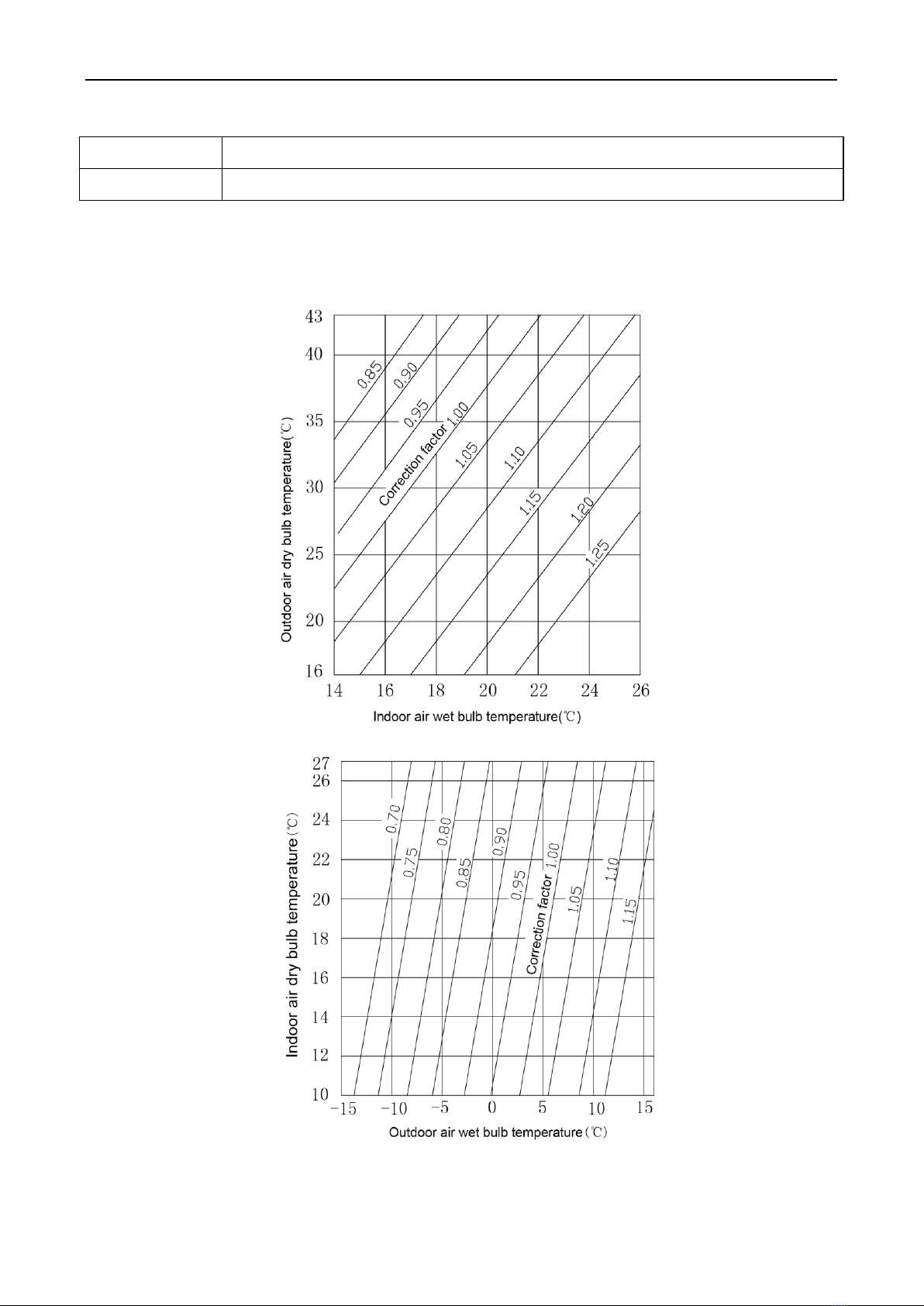
5 PRODUCT CAPACITY CORRECTION..................................................................................................... 4
5.1Correction factor of indoor and outdoor temperature .......................................................................... 4
5.2 Correction factor of pipe length and height difference........................................................................ 5
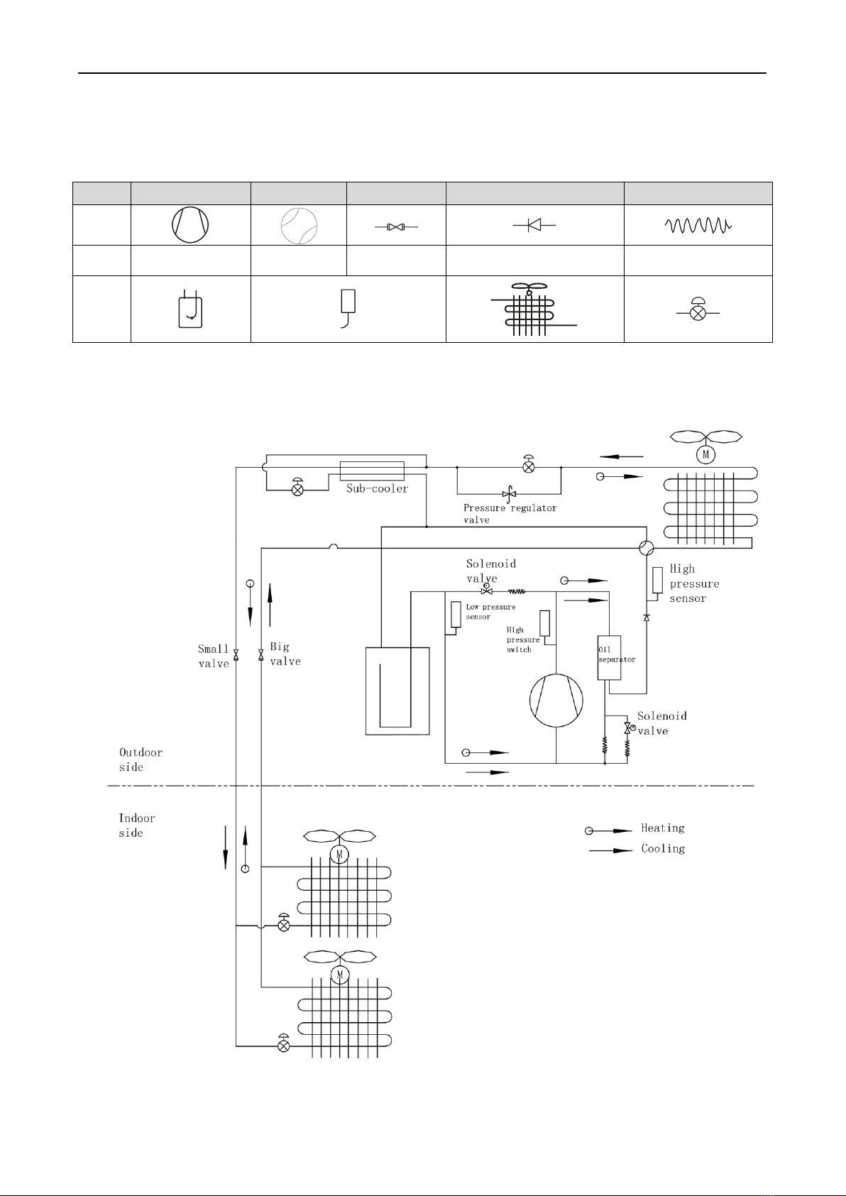
6 PRINCIPAL OF OPERATION.................................................................................................................... 6
CONTROL ........................................................................................................................................ 9
1UNITS’ CONTROL.................................................................................................................................... 9
1.1 Schematic diagram of units’ control ......................................................................................................... 9
1.2 Interpretation on the schematic diagram................................................................................................. 9
2REMOTE MONITORING SYSTEM .......................................................................................................... 9
2.1 General introduction..................................................................................................................................... 9
3MONITORING SOFTWARE................................................................................................................... 10
3.1 Function introduction................................................................................................................................. 10
3.2 Connection of computer and units.......................................................................................................... 10
3.3 Parts introduction........................................................................................................................................ 11
INSTALLATION .............................................................................................................................. 55
1 ENGINEERING INSTALLATION PREPARATION AND NOTICE .......................................................... 55
1.1 Installation notice ........................................................................................................................................ 55
1.2 Installation key points and importance.................................................................................................. 55
2 INSTALLATION MATERIALS SELECTION............................................................................................ 56
2.1 Refrigerant piping........................................................................................................................................ 56
2.2 Condensate water pipe............................................................................................................................... 57
2.3 Insulation material....................................................................................................................................... 57
2.4 Communication cable and control cable............................................................................................... 57
2.5 Power cable................................................................................................................................................... 58
2.6 Hanger rod and support............................................................................................................................. 58
3 INSTALLATION OF OUTDOOR UNIT.................................................................................................... 58
3.1 Check before installation........................................................................................................................... 58
3.2 Selection of installation site...................................................................................................................... 58
3.3 Carrying and installing outdoor unit....................................................................................................... 58
3.4 Installation notices...................................................................................................................................... 59
3.5 Fixing and damping of unit ....................................................................................................................... 59
3.6 Outline dimension and position of installation hole........................................................................... 59
3.7 Installation space requirement................................................................................................................. 60
DEBUGGING &MAINTENANCE.................................................................................................... 61
1 DEBUGGING OF UNIT........................................................................................................................... 62
1.1 Preparation for debugging......................................................................................................................... 6 2
1.2 Debugging of unit........................................................................................................................................ 63
1.3 Parameters reference value for the normal operation of unit.......................................................... 67
2 MALFUNCTION LIST.............................................................................................................................. 69
2.1 Malfunction list for the wired controller................................................................................................. 69
2.2 Status display table for indicators on main board of outdoor unit................................................. 70
3 TROUBLESHOOTING ............................................................................................................................ 78
4 POWER DISTRIBUTION OF UNIT......................................................................................................... 88
4.1 Power distribution of unit.......................................................................................................................... 88
4.2 Main electric parts ....................................................................................................................................... 88
4.3 Circuit diagram............................................................................................................................................. 89

5 REMOVAL OF PARTS................................................................................................................. 91
5.1 Key parts........................................................................................................................................................ 91
5.2 Removal of key parts .................................................................................................................................. 93
6 COMMON MAINTENANCE .................................................................................................................. 104
6.1 Vacuum drying for the system ............................................................................................................... 104
6.2 Fill and charge refrigerant....................................................................................................................... 105
6.3 Airtightness test......................................................................................................................................... 107
7 EXPLODED VIEW OF UNIT AND PARTS’ LIST .................................................................................. 108
7.1 Exploed view for outdoor unit and parts’ list...................................................................................... 108

DC INVERTER VRF SYSTEM II SERVICE MANUAL(R410A)
PRODUCT

C&H DC Inverter Multi VRF System II ServiceManual
1
PRODUCT
1 Product List
Cooling
Capacity
(kW)
Heating
Capacity
(kW)
Power
Supply
Refrigerant
Appearance
R410A
380-415V
3N~50Hz
380-415V
3N~60Hz
R410A
Model
CHV-5S120NK2 12.1 14.0
CHV-5S140NK2 14.0 16.5
CHV-5S160NK2 16.0 18.0
220-240V
50Hz
208-230V
60Hz
CHV-5S120NM2 12.1 14.0
CHV-5S140NM2 14.0 16.5
CHV-5S160NM2 16.0 18.5

C&H DCInverter Multi VRF System II Service Manual
2
2 Nomenclature
3 Product Features
3.1 General introduction
C&H DC Inverter Multi VRF System II is the latest generation of DC inverter units. One set of
air-cooled outdoor unit can be connected with multiple direct evaporation indoor units that are of the
same or different forms and capacity. This refrigerating system can directly provide air conditioning for
one or more areas, and is applicable for residential and light commercial uses. It features high energy
efficiency, strong anti-interference capability, long connectable pipe, wide operation range, good sound
quality, intelligent capacity regulation, complete protection, etc.
3.2 Features
(1) Super high energy efficiency
The 2nd generation of DC Inverter Multi VRF System adopts DC motor to realize complete direct
current and upgrade the energy efficiency. EER is up to 3.97 and COP can reach 4.28.
(2) New generation CAN bus communication
Due to the latest communication method—CAN Bus Communication, system’s anti-interference
capability is stronger and the control on indoor units is more accurate, with higher reliability.
Specialized shield wire is no more needed and ordinary communication wire can be applied in
the construction, which has increased the installation flexibility.
(3) Long connection pipe
The maximum length of connection pipe is 300m (in total) and the farthest connection pipe
between indoor and outdoor units can be 120m’s long, which has extended the installation
condition and reduced the limit of installation distance.
(4) Wide operation range
Units can operate reliably in a wide temperature range (cooling: -5~52℃, heating: -20~27℃).
(5) Fine sound quality
Code of cooling capacity Nominal capacity/100(W)
2.1 Nomenclature of outdoor units
CHV □□□
1 2 34 5
No. Description Options
1 Product code CHV-Cooper&Hunter Multi VRF Units
2
3
4
5
- 5S□
Refrigerant N –R410A
Export K –220-240V 50Hz
Design No. Named in order 1, 2, 3…

C&H DC Inverter Multi VRF System II ServiceManual
3
Through a series of optimized measures, system has reduced the throttle noise and oil return
noise of indoor units, gas bypass noise, etc. so that units are more comfortable regarding sound
quality.
(6) Intelligent PID capacity regulation
With the independently developed PID capacity regulation technology, units are able to control
the indoor ambient temperature more quickly and reduce the fluctuation of room temperature.
(7) Complete protection
Units are equipped with a series of protection to accurately identify errors and protect the units,
which has ensured reliable and safe operation.
4 Specifications
4.1 Specifications
Model
CHV-5S120
NK2
CHV-5S140
NK2
CHV-5S160
NK2
CHV-5S120
NM2
CHV-5S140
NM2
CHV-5S160
NM2
Cooling capacity
kW
12.1
14.0
16.0
12.1
14.0
16.0
Heating capacity
kW
14.0
16.5
18.0
14.0
16.5
18.0
Circulating air
volume
m3/h
6000
6300
6600
6000
6300
6600
Noise
(Sound Power
Lever)
dB(A)
68
69
69
68
69
69
Refrigerant charge
volume
kg
3.3
3.3
3.3
3.3
3.3
3.3
Energy efficiency
level
Level
1
1
1
1
1
1
Power supply
220-240V~50Hz 208-230V~60Hz
380-415V 3N~50Hz 380-415V
3N~60Hz
Rated
power
input
Cooling
kW
3.03
3.59
4.75
3.03
3.59
4.75
Heating
kW
3.27
3.95
4.65
3.27
3.95
4.65
Unit Dimensions
(mm)(WxDxH)
900×340×1345
Package Dimensions
(mm)(WxDxH)
998×458×1500
Compressor
QXAS-F428zX050A
QXAS-F428zX050C
Water-proof level
IPX4
IPX4
IPX4
IPX4
IPX4
IPX4
Suitable climite
T1
T1
T1
T1
T1
T1
Connection
pipe
Gas
mm
Φ15.9
Φ15.9
Φ19.05
Φ15.9
Φ15.9
Φ19.05
Liquid
mm
Φ9.52
Φ9.52
Φ9.52
Φ9.52
Φ9.52
Φ9.52
Connection
Method
Flare
Flare
Flare
Flare
Flare
Flare
Net weight
kg
112
112
112
122
122
122
Note:
①Units conform to design standard: EN 14511.
②Specifications may be changed due to product improvement. Please refer to nameplates of the units.
③Noise data are collected from a semi-anechoic room. Decibels may be slightly higher in actual
operation due to environmental change.
④Refrigerant charge volume listed in the table is based on the condition where indoor and outdoor
units are at a same level and with no connection pipe. Supplementary refrigerant needs to be
charged according to actual circumstance.
⑤The sectional area of conducting wire is only applicable when the length is within 15m. If it’s over
15m’s long, sectional area must be increased accordingly, otherwise, over-current may burn the
wires.

C&H DCInverter Multi VRF System II Service Manual
4
4.2 Operation range
Cooling
Outdoor temperature: -5℃~52℃
Heating
Outdoor temperature: -20℃~27℃
5 Product Capacity Correction
5.1Correction factor of indoor and outdoor temperature
1)Correction factor of cooling capacity
2)Correction factor of heating capacity

C&H DCInverter Multi VRF System II Service Manual
5
5.2 Correction factor of pipe length and height difference
Symbol description:
Hp: Height difference in case indoor unit is below outdoor unit (m);
Hm: Height difference in case indoor unit is above outdoor unit (m);
L: Length of one-way equivalent pipe
Below table shows the capacity variance ratio for 100% full load in standard working condition
(thermostat setting is 16℃for cooling and 30℃for heating).
CHV-5S120NK2, CHV-5S140NK2, CHV-5S160NK2, CHV-5S120NM2, CHV-5S140NM2,
CHV-5S160NM2

C&HDC Inverter MultiVRF System II ServiceManual
6
6 Principal of Operation
Components in flowcharts are presented according to the following table:
CHV-5S120NK2, CHV-5S140NK2, CHV-5S160NK2, CHV-5S120NM2, CHV-5S140NM2, CHV-5S160NM2
Name
Compressor
4-way valve
Cut-off valve
One-way valve
Capillary tube
Symbol
Name
Gas-liquid
separator
Pressure
switch
Pressure
sensor
Axial-flow finned heat
exchanger
Electronic expansion
valve
Symbol

C&H DCInverter Multi VRF System II Service Manual
7
In cooling, the low-temperature and low-pressure refrigerant gas from each indoor heat exchanger
will be merged and inhaled by the compressor and then become high-temperature and high-pressure
gas, which will later be discharged into outdoor heat exchangers. By exchanging heat with outdoor air,
refrigerant will turn to liquid and flow to each indoor unit via Y-type branch or manifold. Pressure and
temperature of the refrigerant will then be lowered by throttle elements before it flows into indoor heat
exchangers. After exchanging heat with indoor air, refrigerant wil become low-temperature and
low-pressure gas again and repeat the circulation so as to realize the cooling effect. In heating, 4-way
valve will be energized to make refrigerant circulate in a reverse direction of cooling. Refrigerant will
release heat in indoor heat exchangers (electric heating elements will also work under certain
circumstance and release heat) and absorb heat in outdoor heat exchangers circularly so as to realize
the heating effect.

C&H DCInverter Multi VRF System II Service Manual
8
CONTROL

C&H DCInverter Multi VRF System II Service Manual
9
CONTROL
1 Units’ Control
1.1 Schematic diagram of units’ control
1.2 Interpretation on the schematic diagram
◆High pressure switch is used to identify system’s high and low pressure. When pressure is too high,
the switch will break off and send a signal to main board. Main board will pass this signal to controller,
where the error will be displayed, and stop unit from working.
◆High/low pressure sensor is used to test unit’s high/low pressure and send real-time data to
controller, which will control each unit’s output according to the control logic.
◆Temperature sensors are used to test the tube temperature of the unit and send data to the
controller, which will control each unit’s output according to the control logic.
2 Remote Monitoring System
2.1 General introduction
C&H CAC Remote Monitoring System is an automatic central management system as well as an
intelligent power management system based on internet or local area network. It can provide a complete
set of air conditioning solutions, including remote monitor, malfunction alarms and visual management,
for the real-time, safe and efficient management of air conditioners.
C&H CAC Remote Monitoring System can save your cost on human resources and equipment
management. User can check the running status of air conditioners, turn units on or off, set temperature
or other functions just by means of a browser (e.g. IE, Firefox, Chrome) in every corner of the world.

C&H DCInverter Multi VRF System II Service Manual
10
3 Monitoring Software
3.1 Function introduction
With the rapid development of building complex, more and more central air conditioners in various
models are used in different places, resulting in inconvenience for the management of air conditioners.
Integrating with telecommunication technology and computing software, C&H Commissioning Tool Kits
can realize the comprehensive monitor, control and commissioning on central air conditioners. It is an
efficient solution for the management of central air conditioners that are separated in different parts of a
building. Administrator doesn’t need to control every unit on site, but rather controls the units by just
sitting in front of a computer. This will not only improve the productivity, but also reduce cost on human
resources, property and management.
C&H Commissioning Tool Kits can monitor and control the 2nd generation of C&H Multi VRF. User
can monitor and control units by monitoring the computer. This software is an efficient tool for the
intelligent air conditioning management as well as installation and after-sales service and commissioning.
It can debug units and control units’ operation status quickly and conveniently. It will not only improve the
productivity but also reduce the difficulty and cost of commissioning and maintenance, providing better
and faster service to customers.
3.2 Connection of computer and units
It can be connected with single-system network or multi-system network. In the single-system network,
indoor units or outdoor units are connectable, while in the multi-system network, only the master outdoor
unit can be connected.
Seen from the diagram, C&H commissioing network is made up of 3 parts:
The 1st part is the monitoring computer, including C&H debugger and C&H USB converter driver that
are installed in the computer.
The 2nd part is C&H USB converter, which is to convert the air conditioning communication into
computing communication. This part is made up of C&H USB data converter and USB data wire.
The 3rd part is air conditioners, including outdoor units, indoor units and the connection wires. If
connection wire is not long enough, it’s OK to connect via the patching board of the commissioning tool

C&H DCInverter Multi VRF System II Service Manual
11
kits. In a single-system network, both indoor units and outdoor units can be connected, while in a
multi-system network, only the master outdoor unit can be connected.
3.3 Parts introduction
3.3.1 List of parts
Name
Model
Material no.
Remark
C&H USB data converter
MC40-00/B
30118027
Convert the air conditioning communication
into computing communication
C&H Commissioning Tool Kits
(CD-ROM)
DG40-33/A(C)
36400000003
Include C&H debugger, monitoring software,
USB driver and USB converter configuring
software.
USB wire
\
40020082
Wire connecting computer’s USB interface
and converter
Communicaiton board
\
30118015
This board can be used when units are far
from the computer.
Board connection wire (1m)
\
4001023229
4-core wire connecting units and converter
Board connection wire (5.5m)
\
4001023214
4-core wire connecting units and converter
Instruction manual
\
66174100018
Instruction manual
3.3.2 C&H USB data converter
3.3.2.1 Functions introduction
C&H USB data converter will convert the RS485, HBS and CAN commucation within the air
conditioners into the communication that is recognizable by computer’s USB interface.
3.3.2.2 Appearance

C&H DCInverter Multi VRF System II Service Manual
12
3.3.2.3 Operation instruction
Power LED: a red light. If the red light is on, it indicates normal power supply. If the red light is off,
it indicates the power supply of converter is not normal.
Communication LEDs: yellow lights. When converter is working and the computer is transmitting
data, the TX data transmitting light will be flickering. When units are uploading data to the
computer, the RX data receiving light will be flickering.
When converter is under RS485 data transferring mode, the function LED of RS485 to USB will
be on.
When converter is under CAN data transferring mode, the function LED of CAN to USB will be
on.
When converter is under HBS data transferring mode, the function LED of HBS to USB will be
on.
USB interface: connect USB data wire.
CAN interface: When converter is under CAN communication mode, connect air conditioner’s
CAN data interface. CAN interface exhibits no polarity (A and B are equal).

C&H DCInverter Multi VRF System II Service Manual
13
HBS interface: When HBS converter is under HBS communication mode, connect air
conditioner’s HBS data interface. HBS interface exhibits no polarity (This interface is not yet
available for C&debugger and the monitoring software).
RS485 interface: When RS485 converter is under RS485 communication mode, connect air
conditioner’s RS485 data interface. RS485 interface exhibits polarity and terminal A and B are
different.
3.3.2.4 Installation notice
Install indoors. To avoid collision, it is suggested to place it in the monitoring room together with
the computer.
No need of power supply. Power is supplied through computer’s USB interface.
3.3.3 Communication board
Communication board is mainly used for transferring data. It functions similar with a patching board.
Provided that units are far away from the monitoring computer, communication board can be used for
connection.
3.3.4 Communication cord
3.3.4.1 USB wire
Connect USB wire with computer’s USB interface at one end and with the USB interface of USB
data converter at the other end, as indicated below:
3.3.4.2 Board Connection Wire
There are 2 board connection wires supplied for the commissioning tool kits. One is 1 meter’s
long and the other is 5.5 meters’ long. They are only different in length. One end of the wire shall
connect with air conditioner’s communication interface and the other end shall connect with CAN
interface of C&USB converter. As shown below, the wire can be connected to the
communication interface of outdoor unit or the communication interface of indoor unit:
USB Wire

C&H DCInverter Multi VRF System II Service Manual
14
3.4 Software introduction
(1)One-button commissioning
Personnel responsible for the commissioning of air conditioners can start commissioning by
pressing one button according to the commissioning logic of software, which will give the
commissioning order to units. Then commissioning will be started up automatically step by step.
During the commissioning, the corresponding process will be ticked in green on the software
interface. If any commissioning process is not normal, it will be displayed in red.
(2)Comprehensive monitoring
The software can monitor every part of the air conditioning system, including functions, equipment
and components operating status. The monitoring results will be displayed in text or curve so that
user can acquire the operating status of the entire system conveniently and straightforwardly.
(3)Real-time control
Air conditioner’s operating time and requirements may be different based on areas and functions.
User can set units’ parameters on computer according to actual needs, such as the on/off,
temperature, fan speed, mode, etc. Meanwhile, the software can also set or view the function
parameters of outdoor units, gateway and other equipment. In this way, the mangement of central
air conditioners is realized.
(4)Replay history
Software can replay and save the historical monitoring information in the data base. The replay
speed can be selected and the information will be shown in text or curve. This function has greatly
saved the time to track problem cause and resolved the difficulty of problem reproduction.
(5)Applicable to multiple series, models and users
C&H Commissioning Tool Kits is applicable to air conditioning system that comsists of multiple
series and models. Later, it will be developed to cover all series of C&H central air conditioners,
such as multi VRF, centrifugal chiller, screw type chiller, ground source heat pump units, modular
units, fan coiled units, close control units, etc. It can be used by system and controller designers to
develop and monitor units, or used for maintenance and commissioning.
(6)Other functions
For the convenience of users, the software has added functions like connection guide, printing
screen, opening database folder, rebuilding database, changing database saving path, etc.
Board Connection Wire

C&H DCInverter Multi VRF System II Service Manual
15
3.4.1 Software installation
3.4.1.1 Installation requirements
(1)Computer Configuration
Memory
1 GB at least
2 GB or above is preferred
Hard Disc
10 GB available
CPU
Core 2 or higher
1 GHz at least
2 GHz or above is preferred
Operation System
Windows Server 2003 SP3 or higher
Windows XP SP3 or higher
Windows Vista
Windows 7
(2) CD Playing
Make sure you have administrator access to the computer and there is a CD-ROM in the computer.
Put the CD into the CD-ROM. If it’s automically running, then the following display will be shown. Or
double-click the file “Launcher.exe”.
For the first time to use C&H Commissioning Tool Kits, install these programmes: .Net Framework
4.0, USB Data Converter, Access Driver (necessary for versions below OFFICE 2007), C&H Debugger.

C&H DCInverter Multi VRF System II Service Manual
16
3.4.1.2 Installation flowchart
Button Graphics
This flowchart describes basically the software installation process. See below for details.
3.4.1.3 Installation process
(1) Install .Net Framework 4.0
If your computer has installed .Net Framework 4.0 or versions above, there’s no need to install
again. Otherwise, click “Install .Net Framework 4.0”.
Other manuals for CHV5 Series
1
This manual suits for next models
6
Table of contents