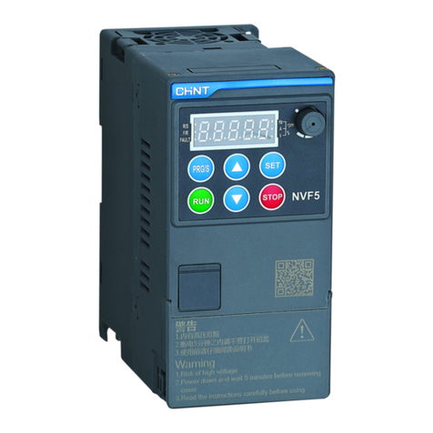
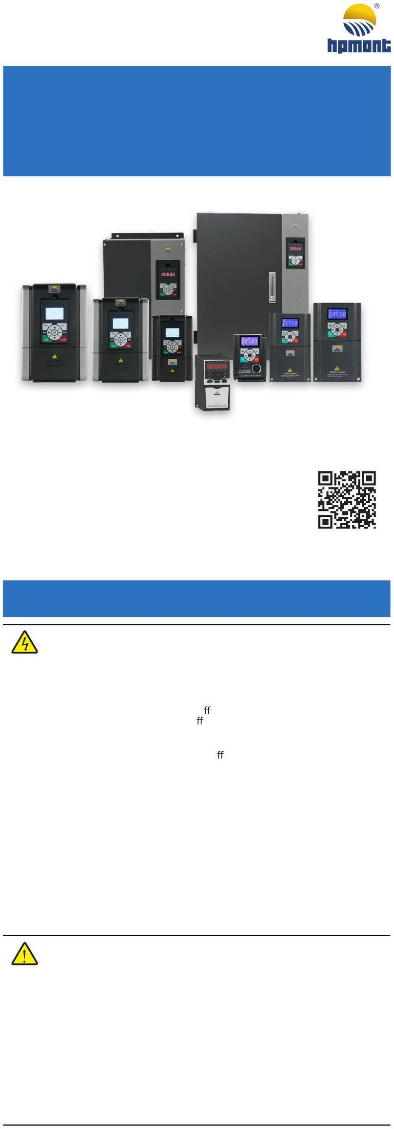
CHINT NVF5 Series User manual


NVF5 Series Inverter Preface
Preface
Thank you for choosing Chint NVF5 series Inverter.
NVF5 series Inverter adopts the speed sensorless vector control technology, It has
the features of fast load response, low frequency high torque and strong overload
capability,Realized the precise control of industrial equipments.NVF5 series inverter has
performance of stable voltage output、torque limited、speed track、simple PLC、process
PID etc.Satisfying the requrements of many industrial equipments,such as Drawing
Machine、Textile、Macine Tools、Logistic、packaging、Food、Plastic Cement、Fans and
Pumps.
NVF5 series Inverter are designed with internal EMC circuit to depress
electromagnetic interference and full thinking of EMC、dust、oil pollution of the customer
site.The modular design of NVF5 can reduce dust and oil stains into the machine.All NVF5
series can realize IP22 with optional top protective cover.
NVF5 series Inverter has three levels parameter menus:Simple mode,Customized
mode and Engineering mode.Be able to meet requirement of different users.The simple
mode is easy to learn,is intended for beginners;The custom mode is able to customize
specific parameter menu,is intended for specific equipment debugger;The engineering
mode contains all user parameters,is intended for professional engineers.
The manual is intended for qualified personnel and provided instructions and
features of NVF5, including Product selection, installation and programming, parameter
explanation, etc. To ensure proper use of the inverter, please read this manual carefully
before using. Plase save it for using later.
If having any problems which cannot be solved during use, please contact
corresponding Chint channels or directly contact the Chint technical personnel for help.
(Customer service phone: 400-1177-797)
The company reserves the right to constantly optimize and improve NVF5 series
inverter, information is subject to change without notice.

NVF5 Series User Manual Table of Content
Table of Contents
Chapter 1 Safety Information .................................................................... - 1 -
1.1 Safety Definition...............................................................................................- 1 -
1.2 Safety Precautions...........................................................................................- 1 -
1.3 Precautions for Users.......................................................................................- 3 -
1.4 Notice of Scrap.................................................................................................- 5 -
Chapter 2 Product Overview..................................................................... - 6 -
2.1 Catalog Numbers Description ..........................................................................- 6 -
2.2 Nameplate Description.....................................................................................- 6 -
2.3 Specifications and Models................................................................................- 6 -
2.4 Technical Specifications...................................................................................- 7 -
2.5 ProductAppearance and Diagram...................................................................- 9 -
2.6 Product Dimensions and Weights..................................................................- 10 -
2.7 IP22 Top Protective Cover Description........................................................... - 11 -
Chapter 3 Installation and Wiring ...........................................................- 13 -
3.1 Peripherial Components Description..............................................................- 13 -
3.2 Peripherial Components Selection and Guideline..........................................- 13 -
3.3 Installation......................................................................................................- 16 -
3.4 Description of the cover..................................................................................- 17 -
3.5 Wiring of Power Terminal and I/O Terminal....................................................- 18 -
3.6 I/O Terminal Description.................................................................................- 22 -
3.7 EMC Precautions...........................................................................................- 24 -
Chapter 4 Integral Keypad....................................................................... - 26 -
4.1 Integral Keypad Instructions...........................................................................- 26 -
4.2 Integral Keypad LED Light and Display..........................................................- 27 -
4.3 Parameter Menu Mode...................................................................................- 29 -
4.4 Integral Keypad Lock and Password Setting..................................................- 32 -
Chapter 5 Simple Parameter Menu and Commissioning Process.........- 34 -
5.1 Simple Parameter Menu List..........................................................................- 34 -
5.2 Simple Commissioning Process.....................................................................- 36 -
Chapter 6 Parameter Function Description............................................- 38 -
6.1 Start Source Setting.......................................................................................- 38 -
6.2 Frequency Reference Setting.........................................................................- 42 -
6.3 Start and Stop Setting....................................................................................- 57 -
6.4 Motor Auto Tuning..........................................................................................- 62 -
6.5 V/F Parameters..............................................................................................- 64 -
6.6 Vector Control Parameters.............................................................................- 67 -
6.7 OverCurrent Stall Protection ..........................................................................- 71 -
6.8 OverVoltage Stall Depress.............................................................................- 71 -
6.9 Protective Function ........................................................................................- 72 -
6.10 Monitoring Function......................................................................................- 78 -
6.11 I/O Terminal Parameter Setting ....................................................................- 78 -
6.12 Ride Through Function.................................................................................- 85 -
6.13 Jogging.........................................................................................................- 86 -
- 1 -

NVF5 Series User Manual Table of Content
6.14 Skip Frequency............................................................................................- 87 -
6.15 Forward and Reverse Switch.......................................................................- 87 -
6.16 Regenerative Braking...................................................................................- 88 -
6.17 Frequency Detection Output(FDT)..........................................................- 88 -
6.18 Output Current Zero Point Detection............................................................- 89 -
6.19 Running Timer..............................................................................................- 89 -
6.20 Start At Power Up.........................................................................................- 90 -
6.21 Sleep Wake Mode........................................................................................- 90 -
Chapter 7 Troubleshooting......................................................................- 91 -
7.1 Diagnostic ......................................................................................................- 91 -
7.2 Abnormal Operation and Solution ..................................................................- 95 -
Chapter 8 Maintenance............................................................................ - 97 -
8.1 Maintenance Instructions ...............................................................................- 97 -
8.2 Maintenance Items.........................................................................................- 97 -
8.3 Routine Maintenance.....................................................................................- 98 -
8.4 Regular Maintenance.....................................................................................- 98 -
8.5 Spare Parts Replacement..............................................................................- 99 -
8.6 Storage.........................................................................................................- 100 -
Appendix A RS485-MODBUS Communication Instructions ................- 101 -
A.1 Networking Mode.........................................................................................- 101 -
A.2 Interface Mode.............................................................................................- 101 -
A.3 Communication Mode..................................................................................- 101 -
A.4 Protocol Format...........................................................................................- 102 -
A.5 Protocol Application .....................................................................................- 103 -
A.6 Control Command, State Information and Fault Information........................- 105 -
A.7 Parameter Management..............................................................................- 108 -
A.8 Network Wiring ............................................................................................- 109 -
A.9 Definition of Communication Exception Code..............................................- 109 -
Appendix B Parameter list ....................................................................- 111 -
Appendix C Accessiories ......................................................................- 142 -
Quality Commitment..............................................................................- 143 -
- 2 -

NVF5 Series User Manual Chapter 1 Safety Information
Chapter 1 Safety Information
Before conducting transfer, installation, running and maintenance, please read the
user manual carefully and conform to all safety guidelines for the application. Failue to
comply may result in personal injury and/or equipment damage or even death of people.
In the event of personal injury and equipment damage caused by noncompliance with
the safety guidelines by you or your clients, Chint can not assume any responsibility.
1.1 Safety Definition
1.2 Safety Precautions
1.2.1 Before installation
Attention
Installation is not allowed in case that the nameplate is inconsistent with your order
requirements!
Installation is not allowed in case that material
objects are inconsistent with the packing
list!
1.2.2 Installation
Danger
Installation must be conducted by qualified personnel in case of the danger of electric
shock!
Please install the inverter on the metal equipmen(supplementary enclosure) or
other
non-combustible objects in case of the danger of fire!
It is not permitted to place combustibles nearby in case of the danger of fire!
The products should be installed with either fuses or an input circuit breaker between
the inverter and power supply in case of danger of fire!
!
Sign
Description
Danger
The occasion where death or serious injury may be caused by the
mis-operation.
Attention
The occasion where intermediate or slight injury or property damage may be
caused by mis-operation.
Danger
In case of a damaged inverter or components lack, it is not suggested to conduct
installation or running; otherwise, the danger of fire or injury may be caused!
It is not allowed to contact with the power terminals, the control circuit terminals
,
electronic parts and components of the inverter by hand directly!
!
- 1 -

NVF5 Series User Manual Chapter 1 Safety Information
It is not permitted to install the inverter in an environemnt containing explosive gases in
case of the danger of explosion!
It is not permitted to insall the inverter at a place directly exposed in sunlight in case of
the danger of equipment damage!
It is not permitted to install the inverter on occasions where water splashing in case of
the danger of equipment damage!
1.2.3 Wiring
1.2.4 Running
Attention
In the transfer process, it is not allowed to make the integral keypad and the cover plate
under pressure in case of the danger that they fall off and damage equipment and
person!
Please install the inverter on the place capabel of bearing the weight in case that the
inverter falls off and damages equipment and person!
In the installation process, it is not permitted to leave metal objects in the machine in
case of the danger of fire!
Danger
Wiring must be conducted by qualified personnel in case of the danger of electric
shock!
Wiring
is not allowed to be conducted unless complete disconnection of the input power
is confirmed in case of the danger of electric shock!
The ground terminal of the inverter must be reliably grounded in case of the danger of
electric shock!
The exposed parts
of cables used for main circuit connection must be well wrapped
with insulating tape in case of the danger of electric shock!
It is not allowed to realize short circuit between P and B in case of the danger of fire and
equipment damage!
The main circuit te
rminal and the cable lug must be connected firmly in case of the
danger of equipment damage!
The I/O terminals besides RA, RB and RC are prohibited to wire with AC 23
0V in case
of the danger of equipment damage!
Attention
The voltage withstand test has been finished before leaving the factory; the users no
longer have to conduct the test again, otherwise the improper test could damage the
device!
When the cable length of the motor is greater than 50 meters, output AC reactor is
suggested in case of the danger of equipment damage!
!
!
- 2 -

NVF5 Series User Manual Chapter 1 Safety Information
1.3 Precautions for Users
Danger
The inverter must be covered with the cover plate before power on in case of the
danger of electric shock and explosion!
The inverters which have been stored for more than 2 years must been done
precharge
experiment. When energized, the voltage regulator is used to slowly increase the
voltage in case of the danger of electric shock and explosion!
During power-on, it is not allowed to touch the terminals by hand in case of the danger
of electric shock!
It is not permitted to operate the inverter with a damp hand in case of the danger of
electric shock!
After replacing control boar
ds,the inverter will begin running after parameters are
correctly set in case of the danger of equipment damage!
The products is intended for qualified personnel to test during running in case of the
danger of personal injury or equipment damage!
Please don’t change original factory parameters in case of the danger of equipment
damage!
Attention
Please ensure the power phase and rated voltage are consistent with the nameplate of
the product in case of the danger of equipment damage!
Check connection of the main circuit of the inverter to ensure disappearance of short
circuit and fastened conenction in case of the danger of equipment damage!
It is not permitted to control the inverter start and stop frequently in a power-
on and
power-off mode in case of the danger of equipment damage!
Safety
Information
Description
Compared with
power frequency
running
The inverter is a voltage source type machine and the output
voltage is PWM waves including harmonics. Therefore, the
temperature rise, noise and vibration of the motor will slightly
increase compared with power frequency running.
Constant-torque
low-speed
running
When the inverter drives common AC induction motor to run at a
low speed for a long term, the output torque maybe reduced due to
the heat dissipation effect of the motor. If it is required to run at a
low speed and constant-torque for a long term, a variable frequency
motor must be used.
Electronic thermal
protection value
of motor
When using an adaptive motor, the inverter could perform thermal
protection on the motor. In case that the motor is not matched with
the inverter in rated capacity, the protection threshold value must be
adjusted or other protection must be taken for guaranteeing safe
running of the motor.
Running over
50Hz
In case that the motor runs at the frequency over 50Hz, in addition
to increase of the vibration and noise of the motor, the applied
!
- 3 -

NVF5 Series User Manual Chapter 1 Safety Information
speed range of motor bearings and mechanical devices must be
ensured, please inquiry in advance if having questions.
Lubrication of
mechanical
devices
The gearbox, gears and other mechanical devices needing
lubrication probably be damaged when running at a low speed for a
long term , please inquiry in advance if having questions.
Negative torque
load
For lift load , negative torque is often generated, the inverter may
trip due to overcurrent or overvoltage, and then a appropriate brake
assembly should be selected.
Mechanical
resonance point
of load
Within the output frequency range, the inverter may encounter the
mechanical resonance point of the load, now the skip frequency
shold be selected.
Occasion of
frequently start
and stop
Selecting DI terminals to control the start/stop of the inverter. It is
prohibited to use contactors and other switching devices at the input
side of the inverter for direct and frequent start/stop in case of
equipment damage.
Motor insulation
check before
connection to
inverter
When the motor is used for the first time or before the motor is used
again after being placed for a long time, insulation check shall be
conducted to prevent the effectiveness of insulation of a motor
winding in case of the damage to the inverter. Wiring is shown in the
following figure. In the testing process, it is supposed to adopt a
500V voltage type megger and guarantee that the insulation
resistance is not less than 5MΩ.
Capacitor or
voltage
dependent
component for
improving power
factors
Since the inverter PWM output waveform, fault trip of the inverter or
damage to devices may be caused if a capacitor or an anti-thunder
piezoresistor installed at the inverter output must be removed.
Contactor and
switching devices
installed on the
output of the
inverter
If a contactor and other switching devices will be used between the
output of the inverter and the motor, please ensure that switch
operation is performed on the inverter whitout running; otherwise,
the inverter may be damaged.
Outside rated
voltage
It is not suggested to use the inverter beyond the allowable
operating voltage range, and please use a corresponding voltage
increasing/decreasing device for voltage transformation if needed.
Lightening surge
protection
A surge protection device installed in the inverter.The inverter has
certain self-protection ability to inductive thunder.
Altitude and
In the areas at the altitude exceeding 1000 meters, The inverter can
- 4 -

NVF5 Series User Manual
1.4 Notice of Scrap
derating
application
be used with dreating. The following figure shows a relation curve of
the rated current of the inverter and altitude.
Current
Altitude
100%
90%
80%
1000m 2000m 3000m
Danger
The electrolytic capacitor of the main circuit and the electrolytic capacitor on the printed
board may explode in the burning process.
Plastic parts such as the panel may produce poisonous gases when burning.
Please treat the discarded inverter as industrial waste.
- 5 -

NVF5 Series User Manual Chapter 2 Product Overview
Chapter 2 Product Overview
2.1 Catalog Numbers Description
Applicable
Motor Power
(kW)
T: Universal
Model
Number of
Inverter Input
Phases
D: Single
Phase
S: Three
Phases
Input Voltage
Rating
2:230V
4:380V~ 440V
Brake Unit
B: Standard
Embedded
Blank: No
Embedded
NVF5 0.4 TD 2 B
Product
Model
/
Figure 2-1-1 Products Naming Rules
2.2 Nameplate Description
NOTE:NVF5 Serieal Inverters maintained CE certificate and complied with European Low
Voltage(LVD) Directive and Electromagnetic Compatibility(EMC) Directive.
Figure 2-2-1 Nameplate
2.3 Specifications and Models
1.Product
2.Catalog No.
3.Power Rating
4.Rated Input
5.Rated Output
6.Standard
8.Factory No.
7.CE Certificate
- 6 -

NVF5 Series User Manual Chapter 2 Product Overview
Table 2.1 Inverter Model and Specification
Power
Supply Catalog No. Power
Capacity
kVA
Input
Current
A
Output
Curren
t
A
Adaptiv
e Motor
kW
Brak
e
Unit
Single-Phase
AC 230V
NVF5-0.4/TD2 1.0 5.4 2.5 0.4
Optio
nal(e
mbed
ded)
NVF5-0.4/TD2-B
NVF5-0.75/TD2 1.9 10.3 5 0.75
NVF5-0.75/TD2-B
NVF5-1.5/TD2 2.9 15.5 7.5 1.5
NVF5-1.5/TD2-B
NVF5-2.2/TD2 4.2 20 10 2.2
NVF5-2.2/TD2-B
Three-Phase
AC
380V~440V
NVF5-0.4/TS4-B 0.8 2.3 1.5 0.4
Stan
dard(
embe
dded)
NVF5-0.75/TS4-B 1.5 3.4 2.7 0.75
NVF5-1.5/TS4-B 3.0 5.1 4.2 1.5
NVF5-2.2/TS4-B 4.0 6.6 5.8 2.2
NVF5-3.7/TS4-B 5.9 12.1 10.5 3.7
NVF5-5.5/TS4-B 8.6 13.1 13 5.5
NVF5-7.5/TS4-B 11.0 22.2 17 7.5
2.4 Technical Specifications
Form2.2 Specifications
Item
Description
Input Voltage range Three-phase 380~440V :
380 V
(-15%)
~440 V
(+15%
)
Single-phase 230V:230 V(±15%)
Frequency range (47~63)Hz
Output
Voltage 0~rated input voltage
Frequency (0~400)Hz
Overload capacity 150%of rated current for up to 1 minute,and 180%
of
rated current for up to 2 seconds
Main control
function
Control mode SVC control、V/F control、Torque control
Start torque SVC:150% rated torque at 0.5Hz
V/F:100% rated torque at 1Hz
Carrier frequency
1kHz~15kHz
- 7 -

NVF5 Series User Manual Chapter 2 Product Overview
Speed range
SVC:1:100;V/F:1:50
Speed control
accuracy
±0.5% of peak speed in SVC mode
Frequency
resolution Digital setting:0.01Hz;
Analog setting:Max. frequency×0.5%
V/F curve Linear V/F curve;(2、1.7、1.2、multi-point)power
reduced torque curve
Accel./Decel.curve
4 types of linear Accel./Decel. curve;S-curve
Accel./Decel.
Distinct features
Over-current stall protection, over-voltage stall
protection, torque limit, RPM tracking, simple PLC,
process PID, multi-segment speed control, automatic
slip compensation, automatic torque boost,
pre-excitation function, instant power cut function
Peripheral
interface
Digital input
5 multifunctional digital programmable input (including
1 high-speed pulse input terminal)
Digital output
1 multifunctional digital programmable output (speed
up to 100kHz)
Analog input
2 analog signal input, (0~20)mA, (4~20)mA current
signal input or (0~10)V, (-10~+10)V voltage signal
input can be selected
Analog output
1 analog signal output, (0~20)mA, (4~20)mA current
signal output or (0~10)V, (-10~+10)V voltage signal
output can be selected
Relay output
A pair of N.O. contacts and a pair of N.C. contacts,
contact capacity: 3A/250V
Communication
interface
Standard RS485 communication. External operation
panel can be connected;
Braking function
Embedded braking unit is optional for single-phase
models, and standard for three-phase models.
Operation panel
Display of over 20 parameters including frequency
setting, output frequency, output voltage, and output
current.
Protection function
Protections against over-current, over-voltage,
under-voltage, overheat, overload, input phase loss,
output phase loss, load loss, and motor ground short
circuit.
Environment
Occasion
The occasion is supposed to be indoor, not directly
exposed in sunlight and free of dust, corrosive gas,
combustible gas, oil mist, water vapor, water drops or
saline matter.
Altitude
Without derating below 1000 meters. Above 1000
meters derate 10% for every 1000 meters but shall not
exceed 3000 meters.
Temperature (-10~+45)℃
- 8 -

NVF5 Series User Manual Chapter 2 Product Overview
(Temperature at(45~50)℃,derate 1% for every 1
℃
Humidity (5~95)%RH,non-condensing
Vibration
Vibration accel. speed≤5.8m/s²
Storage (-40~+70)℃
Structure IP level IP20(Standard),IP22 with accessories
Cooling mode
Cooling Fan
Materials
Plastic for all series
Installation mode ≤2.2kW Din rail or screw(Single-phase 2.2kW only
screw);>2.2kW screw
2.5 Product Appearance and Diagram
Figure 2-5-1 NVF5-0.4/TD2~NVF5-2.2/TD2/NVF5-0.4/TS4-B~NVF5-2.2/TS4-B Appearance
Diagram
(The cooling fan of NVF5-2.2/TD2 at the bottom of the Inverter)
- 9 -

NVF5 Series User Manual Chapter 2 Product Overview
Figure 2-5-2 NVF5-3.7/TS4-B~NVF5-7.5/TS4-B Appearance Diagram
2.6 Product Dimensions and Weights
W
H
D
H1
W1
d
63.4
Figure 2-6-1 NVF5-0.4/TD2~NVF5-2.2/TD2/NVF5-0.4/TS4-B~NVF5-2.2/TS4-B Appearance
Diagram
- 10 -

NVF5 Series User Manual Chapter 2 Product Overview
W
H
DW1
H1
d
Figure 2-6-2 NVF5-3.7/TS4-B~NVF5-7.5/TS4-B Appearance Diagram
And Installtion Dimension
Table 2.3Dimensions and Weights(Unit:mm)
2.7 IP22 Top Protective Cover Description
Catalog No. W H D W1 H1
Mounting
hole d
Weight
kg
NVF5-0.4/TD2
75 148 125.2 64 137.5 Φ5.3 1.2
NVF5-0.4/TD2-B
NVF5-0.75/TD2
NVF5-0.75/TD2-B
NVF5-1.5/TD2
NVF5-1.5/TD2-B
NVF5-2.2/TD2 75 148 146.7 64 137.5 Φ5.3 1.25
NVF5-2.2/TD2-B
NVF5-0.4/TS4-B
75 148 125.2 64 137.5 Φ5.3 1.03
NVF5-0.75/TS4-B
NVF5-1.5/TS4-B
NVF5-2.2/TS4-B
NVF5-3.7/TS4-B 89.5 206 149.2 78.5 196.8 Φ5.5 1.79
NVF5-5.5/TS4-B
NVF5-7.5/TS4-B 118 216 163.4 105 205 Φ6 2.78
- 11 -

NVF5 Series User Manual Chapter 2 Product Overview
An optional Top Protective Cover may be selected to realize IP 22 protection level.The Top
Protective Cover consists of two parts:Protective Cover and Bracket.You can refer to the figure 2-6-3
to install(a Installing Bracket ;b InstallingProtective Cover),Apperance after being installed
shown as Figure 2-6-4
Figure 2-6-3 Installing Bracket and Proctive Cover diagram
Figure 2-6-4 Apperance after being installed
- 12 -

NVF5 Series User Manual Chapter 3 Installation and Wiring
Chapter 3 Installation and Wiring
3.1 Peripherial Components Description
3.2 Peripherial Components Selection and Guideline
- 13 -

NVF5 Series User Manual Chapter 3 Installation and Wiring
3.2.1 Input AC Reactor Descriptions
The AC input reactor are used to reduce harmonics and improve impedance.When
the enviroment need higher harmonic requirements,an optional AC input reactor should be
selected.Please refer to the reactor specifications of reactor provider below.
Power
Supply
Catalog No.
Input Current
A
AC input reactor
Three-Phas
e
AC380V~440
V
NVF5-0.4/TS4-B 2.3 ACL-00037-AL8M40-2L
NVF5-0.75/TS4-B 3.3 ACL-00037-AL8M40-2L
NVF5-1.5/TS4-B 5.1 ACL-00050-AL4M20-2L
NVF5-2.2/TS4-B 6.6 ACL-00075-AL3M00-2L
NVF5-3.7/TS4-B 12.1 ACL-0010-AL2M20-2L
NVF5-5.5/TS4-B 13.1 ACL-0015-AL1M42-2L
NVF5-7.5/TS4-B 22.2 ACL-0020-AL1M08-2L
3.2.2 Brake Resistor Description
Table 3.1 Brake Resistor Specifications
Catalog No. Input Current
A
Recommend
ed Circuit
Breaker
A
Recommend
ed
Contactor
A
Cable
Specificatio
n
mm²
NVF5-0.4/TD2 5.4 16 10 2.5
NVF5-0.4/TD2-B
NVF5-0.75/TD2 10.3 25 16 2.5
NVF5-0.75/TD2-B
NVF5-1.5/TD2 15.5 32 25 4
NVF5-1.5/TD2-B
NVF5-2.2/TD2 20 40 32 6
NVF5-2.2/TD2-B
NVF5-0.4/TS4-B 2.3 10 10 2.5
NVF5-0.75/TS4-B 3.3 10 10 2.5
NVF5-1.5/TS4-B 5.1 16 10 2.5
NVF5-2.2/TS4-B 6.6 16 10 4
NVF5-3.7/TS4-B 12.1 25 16 4
NVF5-5.5/TS4-B 13.1 32 25 6
NVF5-7.5/TS4-B 22.2 40 32 6
- 14 -

NVF5 Series User Manual Chapter 3 Installation and Wiring
Power
Supply
V
Catalog No.
Motor
Power
kW
Brake Unit
Resistance
Value
Ω
Power
W
AC
230V
NVF5-0.4/TD2
0.4
Optional
(embedded)
-- --
NVF5-0.4/TD2-B
NVF5-0.75/TD2
0.75 150 80
NVF5-0.75/TD2-B
NVF5-1.5/TD2
1.5 100 150
NVF5-1.5/TD2-B
NVF5-2.2/TD2
2.2 75 250
NVF5-2.2/TD2-B
AC
380V~440V
NVF5-0.4/TS4-B
0.4
Standard
(embedded)
--
--
NVF5-0.75/TS4-B
0.75
800
80
NVF5-1.5/TS4-B
1.5
400
150
NVF5-2.2/TS4-B
2.2
300
250
NVF5-3.7/TS4-B
3.7
200
400
NVF5-5.5/TS4-B
5.5
150
500
NVF5-7.5/TS4-B
7.5
100
800
Note:The usage and working conditions needs to be considered when selecting brake
resistor. The following is a description of brake resistor selection:
(1)Brake Resistor Calculation
When the output current equals half the rated current of the motor, the same braking
torque can be obtained as the rated torque of the motor,so the rough calculation of brake
resistor is:
=
,is brake voltage, is motor rated current,to ensure that the
inverter is not damaged, the minimum value of the brake resistor is when the
current flowing through the brake resistor is motor rated current. When selecting the
resistance of the brake resistor, it must not be less than the below value.
=
According to the above description, the selection range of brake resistor is:
<
(2)Brake Resistor Power Calculation
The power of brake resistor:
=
The brake resistor power is mainly determined by the brake utilization rate ED%.
Because the braking time of the system is relatively short, the temperature rise of the
braking resistor is not enough to achieve a stable temperature rise.So the principle for
determining the brake resistor capacity is to minimize the brake resistor capacity if the
temperature rise of the brake resistor does not exceed its allowable value (i.e. the rated
temperature rise),The rough algorithm is as follows:
= % =
%,
= 1 ||
is brake resistor derating coefficient(Normally select
)。
- 15 -

NVF5 Series User Manual Chapter 3 Installation and Wiring
R is actual brake resistor resistance,P
is brake resistor power.
3.2.3 Output AC Reactor Descriptions
The cable between Inverter and Motor should not be too long.If the cable is too long,the
distributed capacitance will be large, the harmonic current will be generated easily.
The outputAC reactor should be selected when the motor cable is too long.Please refer
to the table below:
Catalog No.
Input
Current
A
Min.Cable Length
(m)AC output reactor
NVF5-0.4/TS4-B 1.5 50
OCL-00030-ALU2100-1L
NVF5-0.75/TS4-B 2.7 50
OCL-00030-ALU2100-1L
NVF5-1.5/TS4-B 4.2 50
OCL-00050-ALU2000-1L
NVF5-2.2/TS4-B 5.8 50
OCL-00065-ALU1500-1L
NVF5-3.7/TS4-B 10.5 50
OCL-0011-ALU1200-1L
NVF5-5.5/TS4-B 13 70
OCL-0016-ALU900-1L
NVF5-7.5/TS4-B 17 100
OCL-0020-ALU700-1L
3.3 Installation
The inverter shall be installed at an indoor place ,good in ventilation and generally in a
vertical mode. When using inverter, please pay attention to installation distance
requirement. The following are examples of multiple side-by-side installations and multiple
vertical installations.
(1)multiple side-by-side installations
Figure 3-3-1 Side-by-side Installatio Diagram
- 16 -
Other manuals for NVF5 Series
1
This manual suits for next models
15
Table of contents
Other CHINT Inverter manuals
Popular Inverter manuals by other brands
Solax
Solax X1 Series Quick installation guide
APsystems
APsystems QS1 Quick installation guide
SUNBEAMsystem
SUNBEAMsystem MOONRAY Series user manual
MAC3
MAC3 E-Power user manual
Hoymiles
Hoymiles HYS-3.0LV-EUG1 Quick installation guide
Analytic Systems
Analytic Systems Pure Sine 300 Installation and operation manual
