Cooper Crouse-Hinds RLF 25 N Series User manual

&=7HQWRQiYRGNSRXåLWtVLPåHWHY\åiGDW
YHVYpPPDWHĜVNpPMD]\FHXSĜtVOXãQp R
]DVWRXSHQtVSROHþQRVWL&RRSHU&URXVH
+LQGV&($*YHYDãt]HPL
'.0RQWDJHYHMOHGQLQJHQNDQRYHUVWWHVWLO
DQGUH(8VSURJRJUHNYLUHUHV RV'HUHV
&RRSHU&URXVH+LQGV&($*OHYHUDQG¡U
((QFDVRQHFHVDULRSRGUiVROLFLWDUGHVX
UHSUHVHQWDQWH&RRSHU&URXVH+LQGV&($*
HVWDVLQVWUXFFLRQHVGHVHUYLFLRHQRWURLGLRPD
GHOD8QLRQ(XURSHD
(676HGDNDVXWXVMX HQGLWRPDULLJLNHHOHV
Y}LWHNVLGDRPDULLJLVDVXYDVWDVMDRPDVHVW
&RRSHU&URXVH+LQGVL&($*HVLQGXVHVW
),17DUYLWWDHVVDWlPlQNl\WW|R MHHQNllQQ|V
RQVDDWDYLVVDWRLVHOOD(8QNLHOHOOl7HLGlQ
&RRSHU&URXVH+LQGV&($*HGXVWDMDOWDQQH
*5ǼĮȞȤȡİȚĮıșİȚİIJĮȡĮıȘIJȦȞȠįȘȖȚȦȞȤȡȘıİ
ȦȢıİĮȜȜȘȖȜȦııĮIJȘȢǼǼʌȠȡİȚȞĮȗȘIJȘșİȚĮʌȠ
IJȠȞǹȞIJȚʌȡȠıȦʌȠIJȘȢ&RRSHU&URXVH
+LQGV&($*³
+$NH]HOpVL~WPXWDWyWD]DGRWWRUV]iJ
Q\HOYpQD&RRSHU&URXVH+LQGV&($*FpJ
HO\LNpSYLVHOHWpQLJpQ\HO HWLPHJ
,6HGHVLGHUDWHODWUDGX]LRQHGHOPDQXDOH
RSHUDWLYRLQXQDOWUDOLQJXDGHOOD&RPXQLWj
(XURSHDSRWHWHULF LHGHUODDOYRVWUR
UDSSUHVHQWDQWH&RRSHU&URXVH+LQGV&($*
/7âLRVQDXGRMLPRLQVWUXNFLMRVLãYHUVWRVƳ-njVǐ
JLPWąMąNDOEąJDOLWHSDUHLNDODXWLDWVDNLQJRMH
&RRSHU&URXVH+LQGV&($*DWVWRY\EHMHVDYR
ãDO\MH
/9âRHNVSOXDWƗFLMDVLQVWUXNFLMXYDOVWVYDORGƗ
YDUDWSLHSUDVƯWMXVXYDOVWVDWELOGƯJDMƗ&RRSHU
&URXVH+LQGV&($*SƗUVWƗYQLHFƯEƗ
0-LVWJƫXMLWROEXGDQLOPDQZDOILOOLQJZD
QD]]MRQDOLWDJƫRPPLQJƫDQGLUUDSSUHĪHQWDQW
WD&RRSHU&URXVH+LQGV&($*ISDMMLĪRP
1/,QGLHQQRRG]DNHOLMNNDQGHYHUWDOLQJYDQ
GH]HJHEUXLNVLQVWUXFWLHLQHHQDQGHUH(8WDDO
ZRUGHQRSJHYUDDJGELM8Z&RRSHU&URXVH
+LQGV&($*YHUWHJHQZRRUGLJLQJ
36HIRUQHFHVViULDDWUDGXomRGHVWDV
LQVWUXo}HVGHRSHUDomRSDUDRXWURLGLRPDGD
8QLmR(XURSHLDSRGHVROLFLWDODMXQWRGRVHX
UHSUHVHQWDQWH&RRSHU&URXVH+LQGV&($*
3/1LQLHMV]ąLQVWUXNFMrREV XJLZRGSRZLHGQLHM
ZHUVMLMĊ]\NRZHMPRĪQD]DPyZLüZ
SU]HGVWDZLFLHOVWZLHILUP\&RRSHU&URXVH
+LQGV&($*QDGDQ\NUDM
6(Q|YHUVlWWQLQJDYGHQQDPRQWDJHRF
VN|WVHOLQVWUXNWLRQWLOODQQDW(8VSUnNNDQYLG
EH RYEHVWlOODVIUnQ(U&RRSHU&URXVH
+LQGV&($*UHSUHVHQWDQW
6.7HQWRQiYRGQDREVOX X9iPYR9DãRP
URGQRPMD]\NXSRVN\WQH]DVW~SHQLHVSRORþQRVWL
&RRSHU&URXVH+LQGV&($*YR9DãHMNUDMLQH
6/21DYRGLOD]DXSRUDERY9DãHPMH]LNX
OD NR]D WHYDWHSULSULVWRMQHP]DVWRSQLãWYX
SRGMHWMD&RRSHU&URXVH+LQGV&($*Y9DãL
GUåDYL
Betriebsanleitung
Explosionsgeschützte
Deckeneinbau-Notleuchte
Operating instructions
Explosion Protected
Emergency
Recessed Ceiling
light fittings
RLF 25...N
300 8000 2121 D/E (-)

Cooper Crouse-Hinds GmbH
22
22
2
Schaltplan Serie RLF 25..N (18W, 36W)
Wiring diagram series RLF 25..N (18W, 36W)
Schéma des connexions, série RLF 25..N (18W, 36W)
Ausführung/ 2 x 18 W 4 x 18 W 2 x 36 W 4 x 36 W
Version/Modèle
Spannungsbereich AC 230 - 240 V 230 - 240 V 230 - 240 V 230 - 240 V
voltage range AC
Gamme des tensions CA
Frequenzbereich/Frequency range
Gamme des fréquences 50 - 60 Hz 50 - 60 Hz 50 - 60 Hz 50 - 60 Hz
Nennstrom in/A Rated current/A
Courant nom. en A avec: 0,20 A 0,36 A 0,36 A 0,68 A
kurzzeitige Überspannung AC
Transient excess voltage AC <350 V
Surtension transitoire CA
Rated luminous lux: 2700 lm 5400 lm 6700 lm 13400 lm
Luminous flux in emergency operation (1,5h, one lamp)
270 lm (20%) 270 lm (20%) 603 lm (18%) 603 lm (18%)
Luminous flux in emergency operation (3h, one lamp)
216 lm (16%) 216 lm (16%) 436 lm (13%) 436lm (13%)
Light efficiency in operation 70 % 69 % 70 % 69 %
1) optional
2) zulässige Toleranzen gemäß EN 60079-0/max. permissable tolerances accd. EN 60079-0/Tolerances admissible selon EN 60079-0: ± 10 %
RLF 25...N
3
1
1N
2L1
3L4
4 ERROR
5 TEST
6 RET
7 LED -
8 LED
+
EVG
9
10
11
12
13
14
-15
16
+
Lamp
Lamp
L´
L1
N
L2
L3
PE
(1)
(2)
EVG
3
2
1
Lamp
Lamp
10
9
8
7
6
5
4 LED
-
3 LED
+
EVG
12
13
14
15
PE
N
L1
L
2
Lamp 4
Lamp 3
L´
L1
N
L2
L3
PE
2 Bat
-
1 Bat
+
Lamp 2
Lamp 1
11
EVG HF XE
= Typ/Type 2 x 18/36 W
- - - - - - - - - - - - - - - - - - - - - - - - - -
= Typ/Type 4 x 18/36 W
EVG EX-ESAJ4
= Typ/Type 2 x 18/36 W
= Typ/Type 4 x 18/36 W

Cooper Crouse-Hinds GmbH 33
33
3
Montagebilder/Maßzeichnung
Illustrations for mounting/Dimensional drawing
1 2 3
675
4
3b
3a
89 10 11
12
1 - 4
13

Cooper Crouse-Hinds GmbH
44
44
4
1. Sicherheitshinweise:
Zielgruppe:
Elekrofachkräfte und unterwiesene Personen.
- Die Leuchte darf nicht in den Zonen 0 und 20
eingesetzt werden!
- Die Anforderungen der EN 61241-0 und -1 u.a.
in Bezug auf übermäßige Staubablagerungen und
Temperatur, sind vom Anwender zu beachten.
- Die auf der Leuchte angegebenen technischen
Daten sind zu beachten!
- Umbauten oder Veränderungen an der Leuchte
sind nicht zulässig!
- Die Leuchte ist bestimmungsgemäß in
unbeschädigtem und einwandfreiem Zustand zu
betreiben!
- Als Ersatz dürfen nur Originalteile von Cooper
Crouse-Hinds (CCH)CEAG verwendet werden!
- Reparaturen, die den Explosionsschutz
betreffen, dürfen nur von CCH/CEAG oder einer
qualifizierten „Elektrofachkraft“ durchgeführt
werden!
- Lassen Sie diese Betriebsanleitung während
des Betriebes nicht in der Leuchte!
- Beachten Sie die nationalen Unfallverhütungs-
und Sicherheitsvorschriften und die nachfolgenden
Sicherheitshinweise, die in dieser Betriebsanleitung
mit einem ( ) gekennzeichnet sind!
2. Normenkonformität
Diese Leuchte ist zum Einsatz in explosions-
gefährdeten Bereichen der Zone 1,2, 21 und 22 ge-
mäß EN 60079-10 und IN 60079-14 geeignet.
Sie wurde entsprechend dem Stand der Technik und
gemäß DIN EN ISO 9001:2000 entwickelt, gefertigt
und geprüft.
Im Netzbetrieb werden alle Anforderungen der Normen
voll eingehalten. Im Notlichtbetrieb wird der in der
Norm festgelegte Wert der Störaussendung in einem
gewissen Frequenzbereich geringfügig überschritten.
Diese Überschreitung führt bei bestimmungsgemä-
ßem Gebrauch der Leuchte zu keinerlei Beeinträchti-
gung anderer Betriebsmittel.
-Achtung! Die Schutzscheibe ist nicht gegen
Herabfallen gesichert!
-Zum Schließen der Schutzscheibe Schrauben nur
handfest anziehen.(Prüfdrehmoment: 1,5 Nm)
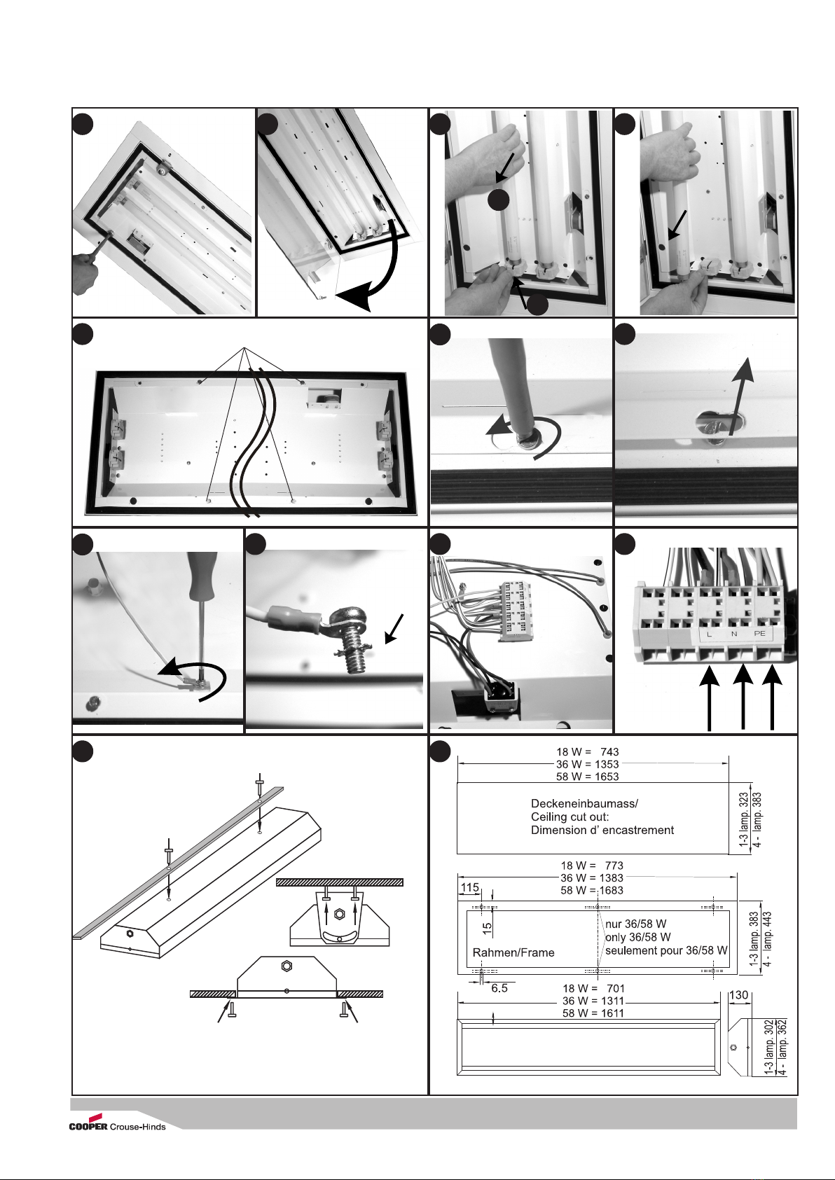
Montageabmessungen: siehe Bild 13
Deckeneinbau (Bild 12 und 13)
Beachten Sie die Maße für den Deckenausschnitt!
1. Gewindebohrungen an der Rückseite
M8 x 18 mm tief zur Deckenmontage.
2. Deckeneinbau in ausreichend tragfähige
Deckenkonstruktionen: seitliche Befestigungs-
löcher im Rahmen mit geeigneten Schrauben
befestigen (Option)
3. Montagebügel zur stirnseitigen Befestigung
(Option) siehe Bild 12
Verwenden Sie keine zu langen Schrauben!
Montagezubehör: s. Cooper Crouse-Hinds-Katalog.
Netzanschluss
-Hängen sie die Schutzscheibe aus den
Scharnieren aus.
-Lösen sie die 4 Befestigungsschrauben am
Reflektor um ca. 3 Umdrehungen (Bild 5, 6)
-Schieben sie den Reflektor nach rechts aus der
Schraube heraus und entnehmen sie den
Reflektor (Bild 7).
-Lösen sie die Schutzleiterverbindung am
Klemmstein oder am Gehäuse (Bild 8). Achten
sie auf die Position der Zahnscheibe (Schrau-
benkopf, Kabelschuh, Zahnscheibe
-Führen Sie die Leitung durch die Ex-Kabel- und
Leitungseinführung ein.
Bei Benutzung der CCH/CEAG Leitungseinführung
M25 (PA) verwenden Sie für Leitungen von 8 bis
12 mm beide Dichtungseinsätze, von 12 bis 17 mm
nur den äußeren Dichtungseinsatz.
Achten Sie auf korrekten Sitz des verbleibenden
Dichtungseinsatzes in der Verschraubung.
-Klemmen Sie die Leitungen an den Anschluss-
klemmen L, L1, L2, L3, N, PE (Bild 10) gemäß
Klemmenbezeichnung an (Bild 11). Abisolierlänge
9-10 mm.
-Schließen sie die Schutzleiterverbindung am
Gehäuse an (Bild 8,9).
-Führen sie den Reflektor in die 4 Befestigungs-
schrauben ein (Bild 7)
-Beim Schließen des Reflektors ist darauf zu
achten, dass keine Leitungen eingequetscht
werden.
-Ziehen sie alle 4 Schrauben fest an.
-Erst danach die Leitungseinführung fest
anziehen
Hängen sie die Schutzscheibe in die Scharnier-
haken ein.
-Führen sie die Lampen in die Fassung ein.
Drücken sie dabei den Betätigungsknopf an der
Fassung (Bild 3a). Die Lampe muss fest in der
Lampenfassung sein. Prüfen sie den festen Sitz
durch leichtes Ziehen an der Lampe (Bild 3b)
-Verschließen sie die Schutzscheibe mit den
Verschlussschrauben (Bild 1)
Achtung
Bei nicht benutzten Kabel-und Leitungseinführungen
ist die Schutzscheibe zu entfernen und durch einen
Verschlussstopfen (Drehmoment 3,5 Nm) zu
verschließen.
Beim Verschließen mit einem Verschlussstopfen stets
beide Dichtungseinsätze verwenden!
Bei Metall-Kabeleinführungen sind die Schutzkappen
der nicht benutzten Einführungen zu entfernen und
durch bescheinigte Ex-Verschlussstopfen
(min. IP 65) zu verschließen!
Einsetzen der Lampe:
3. Technische Daten
EG-Baumusterprüfbe-
scheinigung: FTZÚ 08 ATEX 0188X
Kennzeichnung nach94/9/EG
II 2 G Ex e d mb IIC T4
II 2 D Ex tD A21 IP65 T60 °C
Batterietyp 18 W: 3,6 V / 4 Ah
36 W: 6,0 V / 4 Ah
Notlichtbetriebsdauer: 1,5 h / 3,0 h
(variantenabhängig)
Schutzklasse
nach EN 60 598: I
Schutzart nach EN 60529 IP65
zulässige Umgebungs-
temperatur -5 °C bis +40 °C
Lagertemperatur in der
Originalverpackung: -25 °C bis +60 °C
Lampenbestückung:
Zweistiftlampen-
fassung G13 nach
18 W IEC 60081-22/20
36 W IEC 60081-24/20
Klemmvermögen Anschluss-
klemme 2x je Klemme: 4 mm²
Klemmentyp: Steckklemme
Abisolierlänge: 9-10 mm
Leiterquerschnitt bei Durchgangs-
verdrahtung: 2,5 mm2für max. 16 A
Maximale Anzahl der Leuchten bei
Durchgangsverdrahtung
2x 18 W 12 Stck.
2x 36 W 8 Stck.
4x 18 W 8 Stck.
4x 36 W 3 Stck.
Ex e-Kabel- und Leitungseinführung
Standardausführung: M25x1,5 für Leitungen
Ø 8 bis 17 mm
Metall: M20x1,5 Innengewinde
Prüfdrehmoment für Ex-e Kabel- und
Leitungseinführung M25x1,5: 5,0 Nm
Prüfdrehmoment für Druck-
schraube: 3,5 Nm
(für Abdichtung Leitung
oder Verschlussstopfen)
Prüfdrehmoment für Scheiben-
Schlitzschraube: 1,5 Nm
Gewicht
18/36/ W (2-lampig): ca. 8,9/ 14,9 kg
18/36/ W (4-lampig): ca. 11,5/18,5 kg
4. Funktionelle Besonderheiten
Ladung der Batterie
Bei Netzbetrieb wird die Batterie der Leuchte durch
ein Konstantstrom-Ladeteil geladen.
Das Laden des Batterie wird durch die grüne, leuch-
tende Leuchtdiode im Reflektor angezeigt. Die Ladung
erfolgt über den ungeschalteten Außenleiter L, damit
sie auch bei ausgeschalteter Leuchte nicht unterbro-
chen wird. Der Ladestrom ist bei ordnungsgemäßem
Betrieb der Leuchte so bemessen, dass bei entlade-
ner Batterie innerhalb von 24 h ca. die Nennkapazität
erreicht wird. Er ist für eine Dauerladung der Batterie
geeignet.
Betriebsarten
Bei anliegender Netzspannung können die Lampen in
der Leuchte mit dem Leuchtenschalter ein- und aus-
geschaltet werden.
5. Installation
Halten Sie die für das Errichten und Betreiben
von explosionsgeschützten elektrischen Betriebsmit-
teln geltenden Sicherheitsvorschriften gemäß des
Gerätesicherheitsgesetzes sowie die allgemein
anerkannten Regeln der Technik ein!
Transport und Lagerung der Leuchte ist nur in
Originalverpackung und angegebener Lage gestattet!
Öffnen und Schließen der Leuchte
-Die Schlitzschrauben mit geeignetem Schrauben-
dreher lösen und Schutzscheibe abklappen, siehe
Bild 1 und 2.

Cooper Crouse-Hinds GmbH 55
55
5
Verwenden Sie nur solche Lampen,
die für diese Leuchten zugelassen sind, siehe
Technische Daten und Typenschild!
Achtung: Sicherheitstechnische Hinweise des
Lampenherstellers beachten
Zweistiftsockellampe (G13)
Führen sie die Lampen in die Fassung ein. Drücken sie
dabei den Betätigungsknopf an der Fassung (Bild 3a).
Die Lampe muss fest in der Lampenfassung sein.
Prüfen sie den festen Sitz durch leichtes Ziehen an
der Lampe (Bild 3b).
Achtung! Aufgrund der Selbstentladung der
Batterie ist nach spätestens 6 Monaten auch bei
nicht angeschlossenen Leuchten die Batterie
mindestens 24 Stunden nachzuladen
5. Inbetriebnahme
-Die Leuchte mindestens 24 h eingeschaltet
lassen, damit die Batterie aufgeladen wird.
(grüne Leuchtdiode im Reflektor leuchtet)
-Danach einen Funktionstest der Notlicht-
schaltung durchführen, (siehe 6. Instandhaltung,
Funktionstest).
(grüne Leuchtdiode im Reflektor ist aus)
-Überprüfen Sie vor der Inbetriebnahme die
korrekte Funktion und Installation der Leuchte in
Übereinstimmung mit dieser Betriebsanleitung
und anderen zutreffenden Bestimmungen!
-Führen Sie Isolationsmessungen nur zwischen PE
und Außenleiter L1 (L2,L3) sowie zwischen PE
und N durch!
- Messspannung: max. 1kV AC/DC
- Messstrom: max. 10 mA
Achtung: Eine Isolationsmessung zwischen L und
N darf nicht durchgeführt werden, da sonst die
Elektronik oder die Netzeingangssicherung im VE-
Gerät) zerstört wird.
6. Instandhaltung
Halten Sie die für die Instandhaltung, Wartung
und Prüfung von explosionsgeschützten Betriebsmit-
teln geltenden Bestimmungen z.B. IEC 60079-17 ein!
Wartung:
Im Rahmen der Wartung sind vor allem die Teile, von
denen die Zündschutzart abhängt, zu prüfen z.B.:
-Gehäuse und Schutzglas auf Risse und
Beschädigungen.
-Dichtungen auf Beschädigungen.
-Klemmen und Verschlussstopfen auf festen Sitz.
Lampenwechsel:
-Beachten Sie für den Lampenwechsel die
Wechselintervalle gemäß Vorgabe der Lampen-
hersteller!
-Ein Lampenwechsel kann ohne Freischalten
vom Netz durchgeführt werden, da die
Fassungen beim Öffnen der Schutzwanne durch
einen allpoligen Trennschalter spannungsfrei
geschaltet werden.
Beachten sie jedoch, dass nationale Vorschrif-
ten oder lokale Anwendungsrichtlinien hiervon
abweichend sein können!
Funktionstest Notlicht
Netzspannung der Leuchte ausschalten.
Die Notlichtlampe (grüne Kennzeichnung) muss
leuchten.
Die grüne Leuchtdiode im Reflektor erlischt.
Folgende Prüfzeiten sollten bei einem Funktionstest
nicht überschritten werden, das sonst keine
Notlichtreserve zur Verfügung steht:
Batteriesatz mit 1,5 h Notlicht: 60 min.
Batteriesatz mit 3,0 h Notlicht: 120 min.
Erlischt die Notlichtlampe bei vollgeladener Batterie
innerhalb dieser Prüfzeit, ist ein neuer Batteriesatz
einzusetzen.
Hinweis: Die volle Batteriekapazität steht physika-
lisch bedingt erst nach ca. 3 Lade/Endladezyklen zur
Verfügung!
Instandsetzung
Vor dem Austausch oder der Demontage von
Einzelteilen ist folgendes zu beachten:
Schalten Sie das Betriebsmittel vor dem
Öffnen oder vor Instandhaltungsarbeiten erst
spannungsfrei! Benutzen Sie nur von CCH/CEAG
freigegebene Ersatzteile!
Siehe Ersatzteilkatalog CCH/CEAG.
Programmänderungen und -ergänzungen sind
vobehalten.
Bei der Entsorgung nationale Abfallbeseitigungs-
vorschriften beachten!
Die Kunststoffmaterialien sind mit Material-
kennzeichnungen versehen.

Cooper Crouse-Hinds GmbH
66
66
6
1. Safety instructions
For skilled electricians and instructed personnel in
accordance with national legislation, including the
relevant standards and, where applicable, in acc.
with IEC 60079-17 on electrical apparatus for
explosive atmospheres.
- The light fitting must not be operated in zone 0
and 20 hazardous areas!
- The requirements of the EN 61241-0 and -1
regarding excessive dust deposits and
temperature to be considered from the user.
- The technical data indicated on the light fitting
are to be observed!
- Changes of the design and modifications to the
light fitting are not permitted!
- The light fitting shall be operated as intended
and only in undamaged and perfect condition!
- Only genuine Cooper Crouse-Hinds
(CCH)CEAG spare parts may be used for
replacement!
- Repairs that affect the explosion protection
(see national standard), may only be carried out by
CCH/CEAG or a qualified “electrician”!
- Do not keep these operating instructions
inside the light fitting during operation!
- The national safety rules and regulations for
prevention of accidents and the following safety
instructions which are marked with an ( ) in
these operating instruction, will have to be
observed!
4. Special functional features
Charging the battery
In mains operation the light fitting is charged by
means of a constant current charger. Charging is
shown by the green, lighten LED in the reflector.
Charging takes place via the unswitched external
phase L to prevent an interruption, even when the
luminaire is switched off.
With regular operation of the light fitting the charging
current is measured so that a flat battery will have its
rated capacity within 24 h. It is suitable for a
continuous charge of the battery.
In emergency operation a deep discharge protection
with reclosure preventing device monitors the battery
voltage and prevents the accumulators’deep
discharge.
System modes
When voltage applies, the lamps in the light fitting
can be switched on and off with the light switch.
2. Conformity with standards
The light fitting is suitable for use in zone 1, 21, 2 and
22 hazardous areas acc. to EN 60079-10 and
IEC 61241-10.
It has been designed, manufactured and tested
according to the state of the art and according to DIN
EN ISO 9001: 2000.
All requirements of the standards are fully kept in
mains operation. In the event of interferences being
emitted in emergency operation, there will be a slight
upper deviation from the value defined in the stand-
ard in a certain frequency range.
That deviation does not entail any impairment of any
other apparatus, if the luminaire is duly operated.
3. Technical data
EC type examination
certificate: FTZÚ 08 ATEX 0188X
Category of application:
II 2 G Ex e d mb IIC T4
II 2 D Ex tD A21 IP65 T60 °C
Batterietype 18 W: 3.6 V / 4 Ah
36 W: 6.0 V / 4 Ah
Emergency light: 1,5 h / 3,0 h
(depends on variations)
Insulation class
EN 61140: I
Degree of protection
accd. to en 60529 IP65
Permissable ambient
temperatures 1) -5 °C to +40 °C
storage temperature in
original packing: -25 °C to +60 °C
Fluorescent lamps
bi-pin lamps G13 accd.
18 W IEC 60081-22/20
36 W IEC 60081-24/20
Supply terminal clamping capacity
2 x per terminal: 4 mm²
Terminal type: Plug in terminal
Stripping length: 9-10 mm
Conductor cross-section with
through-wiring: 2.5 mm2for max. 16 A
Max. allowed number of light fittings in through wiring
connection
2x 18 W 12 pcs.
2x 36 W 8 pcs.
4x 18 W 8 pcs.
4x 36 W 3 pcs.
Ex-e cable entry
standard version: M25x1.5 for cable
Ø (8 to 17 mm)
metal thread: M20x1.5
Test torque for M 25 x 1.5 Ex-e
cable entry: 5.0 Nm
Test torque for pressure
screw: 3.5 Nm (for sealing of the
cable or the blanking plug)
Test torque for cover pane
screw: 1.5 Nm
Weight
18/36/ W (2-lamps): ca. 8.9/ 14,9 kg
18/36/ W (4-lamps): ca. 11,5/18,5 kg
5. Installation
The respective national regulations as well as
the general rules of engineering which apply to the
installation and operation of explosion protected
apparatus will have to be observed!
Transport and storage of the luminaire is permitted
in original packing and specified position only!
Opening and closing the light fitting
-unscrew the slotted screws on the cover pane
and open the pane (see fig. 1 and 2)
-Warning! The cover plane is not protected from
drop-down.
-To close the glass pane, press tightly onto the
luminaire housing and hand-screw (test torque
1.5 Nm)
Mounting dimensions: see fig. 13
Recessed ceiling installation: see fig. 12 and 13
Observe the correct ceiling cut-out!
1. For recessed ceiling installation threads are at
the rear side of the enclosure M8 x 18 mm
depth.
2. For recessed ceiling installation into sufficient
capable ceilings use mounting lugs of the
mounting frame with sufficient screws. (option)
3. A mounting bracket can be used for fixing at
the front/back end of the enclosure (option)
Do not use too long screws!
Accessories for mounting: See CCH/CEAG
catalogue.
Mains connection
-Dismount the cover plane from the hinges.
-unscrew the four fixing screws approx. 3 turns
at the reflector's (fig. 5, 6).
-Push the reflector rightwards out of the fixing
screw and take it out (fig. 7).
-Disconnect the protective earth connection from
the terminal or enclosure. Observe the correct
position of the toothed disk (screw head - cable
lug - toothed disk).
-Introduce the cable through the Ex cable entry,
see fig. 5. Use both sealing inserts for cables
from 8 to 12 mm, and the outer sealing insert
only for cables from 12 to 17 mm. Pay attention
to the proper fit of the remaining sealing insert
in the cable gland.
-Connect the conductors to the terminals
L, L1, L2, L3, N, PE (fig. 10) in accordance with
the terminal marking (fig. 11). Stripping length
9-10 mm
-Connect protective earth to the enclosure (fig 8, 9)
-Insert the reflector into the 4 fixing screws (fig. 7)
-While closing the reflector protect wires from
squeezing in.
-Also tighten the 4 screws.
-Now tighten the cable entry.
-Insert the cover plane into the hinges.
-Insert the lamp into the lamp holder while
pressing the operating button (fig. 3a).
The lamp must be secure fixed in the lamp
holder. Check the correct position by slightly
pulling the lamp. (fig. 3b)
- Close the cover plane using the locking screws
(fig.1).
Attention
In case of unused cable entries, remove their protec-
tive cover and close the entries with a blanking plug
(torque of 3.5 Nm). When closing the gland with a
blanking plug, always use both sealing inserts! When
metal cable entries are used, the protective caps of
the unused entries are to be removed and the entries
to be closed with certified Ex blanking plugs!
(min. IP 65)

Cooper Crouse-Hinds GmbH 77
77
7
Fitting the lamps
Only use such lamps that have been certified for
these light fittings, see Technical data and type label!
Note! Observe the safety instructions of the lamp
manufacturer!
Bi-pin lamp (G13)
The lamp is to be inserted to its stop into both hold-
ers, (fig.3a) so that both pins on either side of the
lamp engage in the holder.
Check the correct position by slightly pulling the
lamp. (fig. 3b)
Note! If the ligth fitting is not connect to main
power- more than 6 month, the battery have to
charge 24 h before the light fitting is start ed to
operation.
5. Taking into operation
Prior to operation, check the light fitting for its
proper functioning and installation in compliance with
these operating instructions and other applicable
regulations!
-Leave the light fitting switched on for at least
24 hours so that the battery will be recharged.
The green LED in the reflector is on.
-After that, release a function test of the
emergency light connection, see 7.
Maintenance, function test.
Only carry out insulation measurements between PE
and the external conductor L1 (L, L2, L3) as well as
between PE and N.
– measuring voltage: max. 1 kV AC/DC
– measuring current: max. 10 mA
6. Maintenance
Observe the national regulations applicable to
the maintenance, servicing and test of apparatus for
explosive atmospheres e.g IEC 60079-17 as well as
the general rules of engineering!
Servicing
When servicing, in particular those components that
affect the explosion protection, will have to be
checked, e. g.:
-Housing and cover pane for any cracks or dam-
ages.
-Gaskets for their perfect condition.
-Terminals and blanking plugs for their firm fit.
Lamp replacement
-Lamp replacement: Keep replacement intervals
as specified by the lamp manufacturer!
-Lamp replacement can be done without cut off
the luminaire from mains supply, because an all
pole switch will isolate the lampholders while
opening the protective bowl.
Notice: Observe national standards or directions
for use which can be divergent to this!
Test of the emergency light function
Switch the luminaire off the mains voltage.
The emergency lamp (green marker) must light.
The green LED in the reflector is off
A function test should not exceed the following test
periods:
Battery set for 1.5 h emergency light: 60 min.
Battery set for 3.0 h emergency light: 120 min.
Should the emergency lamp be extinguished within
the test period though the battery is fully charged,
the latter will have to be replaced by a new battery
set.
Mind: The full battery capacity will be available after
approx. 3 charging/discharging cycles due to
physical behaviour.
Repair
Prior to replacing or removing any components,
observe the following:
Cut the apparatus off the voltage before opening it
or carrying out repairs! Only use certified genuine
CCH/CEAG spare parts! (See CCH/CEAG spare
parts list).
Subject to alteration or supplement of this
product series.
Regarding waste disposal, observe the
relevant national regulations! The plastic
materials are marked with material
identifications.

300 8000 2121)/XX/37.08/Str
Technische Änderungen vorbehalten!
Betriebsanleitung gültig ab 09.2008
Cooper Crouse-Hinds GmbHCooper Crouse-Hinds GmbH
Cooper Crouse-Hinds GmbH
Neuer Weg-Nord 49
D-69412 Eberbach
Phone +49 (0) 6271/806-500
Fax +49 (0) 6271/806-476
Internet: www.CEAG.de
E-Mail: [email protected]
ExEx
ExEx
Ex e d mbe d mb
e d mbe d mb
e d mb IIC T4IIC T4
IIC T4IIC T4
IIC T4 60°C60°C
60°C60°C
60°C
(1026)(1026)
(1026)(1026)
(1026)
This manual suits for next models
3
Table of contents
Languages:
Other Cooper Crouse-Hinds Outdoor Light manuals
Popular Outdoor Light manuals by other brands

LightPro
LightPro Nova 5 Manual and safety instructions

Ingo Maurer
Ingo Maurer Zufall T instructions

Orion
Orion AL 11-1123/3 Mounting and safety instructions

LIGMAN
LIGMAN MARYS 1 installation manual

Gartenmetall
Gartenmetall COMO Assembly instructions

Urban Electric
Urban Electric PAM POCKET Assembly and mounting instructions