Cooper safety VoCALL CFVCM Product guide

VoCALL - CFVCM/CFVCWM & CFVCX8
Fir T l phon & Disabl d R fug N twork Syst m
Us r Manual & Log Book

2
VoCALL Fire Telephone & Disabled Refuge Network System
Introduction
A VoCALL Emergency Voice Communic tions System (EVCS) is fixed, secure, bi-direction l, full duplex
voice communic tion system to ssist fire fighters in n emergency in high rise buildings or l rge sites
where R dio communic tion m y not work, nd covers the oper tion of both fire telephones nd
dis bled refuge systems.
The VoCALL EVCS is designed to fully comply with BS5839-P rt 9 ( bb. Pt9) for use s fire telephone
system, dis bled refuge c ll system or s combined system when both fire telephones nd dis bled
refuge points re required.
uitability
Fire telephone systems re recommended for ll public buildings nd multi story buildings over four
floors by BS9999.
Dis bled refuge systems re required in buildings where public or dis bled st ff g in ccess to ny floor
other th n the ground floor using lifts.
Product Overview
A VoCALL EVCS comprises of three function l
blocks, the network m ster h ndset
(CFVCM/CFVCWM) the network eight line
exch nges (CFVCX8) nd outst tions, (type A,
type B, j ck points or emergency ssit l rms),
with the qu ntities of these b sic units being
djusted to suit the pplic tion.
The VoCALL EVCS h s been designed on st r
nd ring network topology; in the most c ses
this will reduce the c ble requirements from ll
ring-b sed systems nd st r systems. The
topology consists of ring formed from either 2
off four core 1mm CSA c bles (soft skin up to
500m per leg, MICC 200m per leg) or 1 four p ir
0.5mm CSA fire r ted d t c ble Dr k 91-021.
The exch nge units nd the control h ndsets sit
on this ring nd communic te using high
speed b l nced RS422 network, bi-direction l
udio p ir nd power p ir, which provides n
ELV m int ined supply to the control h ndsets.
VoCALL EVC System
6-8 Bishops Gate
System Healthy
Navigation
GeneralFault
PanelFault
SupplyFault
ExchangeFault
Healthy
AC
DC
Network
Compliantto 5839-9:2003
VoCALL EVC System
6-8 Bishops Gate
System Healthy
Navigation
GeneralFault
PanelFault
SupplyFault
ExchangeFault
Healthy
AC
DC
Network
Compliantto 5839-9:2003
VoCALL EVC System
6-8 Bishops Gate
System Healthy
Navigation
GeneralFault
PanelFault
SupplyFault
ExchangeFault
Healthy
AC
DC
Network
Compliantto 5839-9:2003

VoCALL Fire Telephone & Disabled Refuge Network System
3
Important afety Information
This equipment must only be installed and maintained by suitably skilled and competent person. This
equipment is defined as Class 1 in EN60950 (Low Voltage Directive) and must be EARTHED.
Each exchange unit requires a 3A spur, returning to a breaker clearly marked EVCS DO NOT TURN OFF.
f the units are distributed around a site it is essential all units are on the same mains phase, as they are
classified TEN 230V, powering from different phases can mean a 440V potential can be present in a unit
during a major fault incident.
ANT -STAT C HANDL NG GU DEL NES
Make sure that electro-static handling precautions are taken immediately before handling PCBs and
other static sensitive components.
Before handling any static-sensitive items, operators should get rid of any electrostatic charge by
touching a sound safety earth, such as a radiator. Always handle PCBs by their sides and avoid touching
any components. PCBs should be stored in a clean, dry place that is free from vibration, dust and
excessive heat.
Storing the PCBs in a suitable cardboard box will also guard them against mechanical damage.
CAUTION NDOOR USE ONLY
WARNING SHOCK HAZARD- SOLATE BEFORE OPEN NG
WARNING TO REDUCE THE R SK OF F RE OR ELECTR C SHOCK,
DO NOT EXPOSE TH S UN T N RA N OR MO STURE
WARNING TH S UN T MUST BE EARTHED
WARNING NO USER SERV CEABLE PARTS

VoCALL Fire Telephone & Disabled Refuge System
4
Powering up the ystem
Carefully check the network wiring then apply AC power to each network exchange unit in turn DO NOT
commission on batteries as the power supply has a large reservoir capacitor which will rupture the
battery fuse if the AC is not present when powering up the system. Once the system is powered, the
battery leads can be attached to the battery.
Batteries
The VoCALL network exchanges require a single 12V 7AH sealed lead acid batteries to provide backup
power in the event of mains failure as defined in BS5839pt9 for 24 hours standby and 3 Hours operation.
For 72hour standby and 1 hour operation a single 12V 17AH battery is required, the monitored charger in
the VoCALL network exchange unit is capable of charging and monitoring these batteries however it
must be located in a separate box
afety Information:
Sealed Lead acid batteries contain sulphuric acid which can cause burns if exposed to the skin,
the low internal resistance of these batteries means large currents will flow if they are accidentally
short circuited, causing burns and a risk of fire- exercise caution when handling batteries.
Power Up Procedure:
Always apply mains power before connecting batteries, do not commission VoCALL Compact on
batteries, as the high inrush current required by the power supply may rupture the battery fuse.
Always connect the Positive (Red +) terminal first.
Power Down Procedure:
Disconnect the batteries before removing the mains power; always remove the negative
(Black – terminal) first.
VoCALL Fire Telephone & Disabled Refuge Network System

Operation
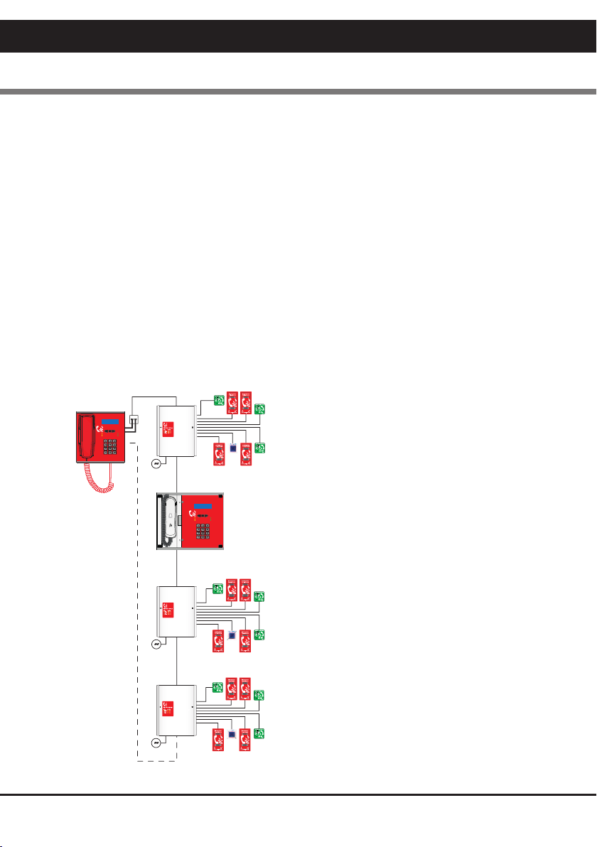
All conversations on the VoCALL network system are under the command of the network master
handset, if multiple network master handsets exist, the first operated one takes command of the system.
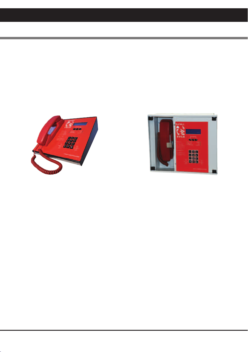
Pt9 envisages the majority of calls to be made by lifting the handset of an outstation (Type A) or pressing
the call button (Type B).
Receiving a Call
When a handset is lifted or the call button is pressed on the Type B units, the phone on the control
point(s) will ring and the name of the calling extension will appear on the LCD display (all exchange lines
can be given a unique 16 character name to identify themselves such as “Floor 1 Riser E”).
The operator can then lift the handset and connect to the calling extension by pressing the # key. f more
than one line is calling, all calling lines show in the display, and may be scrolled through with the
navigate buttons, connected using the # key, or if already connected placed on hold using the # key a
second time.
Making a Call
Lift the handset on the control phone, then either:
Dial the number of the line you require and press # to call, the line will connect automatically when the
remote handset is lifted or the call button is pressed.
Press the * key to scroll the display to the directory page. Once in the directory use the up and down
keys navigation to select the extension name you wish to call, and press # to call. The line will connect
when answered.
Ending or Holding a Call
Both call types can be ended by pressing the # key on the exchange line you no longer wish to call (if
the bell symbol is shown).
Pressing # while a remote outstation is speaking or is off hook will place the line on HOLD (the symbol of
an off hook phone is shown), you can talk to this line again by scrolling to it and pressing # again
Making a Call to Another Master (multi-master systems only):
Lift the handset on the control phone, then either:
Dial the number of the master you require (001 for master 1, 008 for master 8) and press # to call, the
line will connect automatically when the remote handset is lifted or the call button is pressed.
Press the * key to scroll the display to the directory page. Once in the directory use the up and down
keys navigation to select the master name you wish to call, and press # to call. The line will connect
when answered.
5
VoCALL Fire Telephone & Disabled Refuge System
VoCALL Fire Telephone & Disabled Refuge Network System

6
VoCALL Fire Telephone & Disabled Refuge Network System
Indications and Controls
The faults on a VoCALL EVCS system are displayed in two locations, on the exchange with the fault, and
at the CFVCM/CFVCWM master handset(s).
Master Handset Indication
The network master handset has the following indications:-
Health Indicators (Green)
Healthy The system is ready for use and fault free.
AC ndicates healthy AC mains available.
DC ndicates the battery supply is available.
Network The communication network is operating.
Fault Indicators (Yellow)
General Fault A fault exists on the system.
Panel Fault The processor, main phone or watchdog timer have tripped, engineer
assistance is required.
Supply Fault Either the AC supply or DC supply is unavailable, or a fuse has ruptured.
Exchange Fault A fault exists on one of the remote exchanges or an exchange is missing
from the system.
Fault Log
The Fault log can be accessed on the master handset by entering the P N number, this should
only be done by an engineer. Using the navigation key scroll down to view event log to view
faults.
CFVCM CFVCWM

VoCALL Fire Telephone & Disabled Refuge Network System
7
Exchange Indications
The network exchange unit has the following indications:-
LED Meaning
Fault This is a common fault LED and indicates that a current fault exists on this
exchange unit, this can be a line fault, processor failure, power supply fault
or network connection fault.
Supply There is a fault with the power supply section of the exchange unit, this
could be lack of either AC or DC, rupture of a fuse or failure of the VRSLA
cell to hold charge
AC Ok The mains AC voltage is present
DC Ok The backup battery supply and charger are available to operate the
exchange in the event of a mains failure
Line LEDs
All 8-line indicators are identical in operation, and represent the exchange lines (numbered 1 to 8
on the exchange polycarbonate decal).
Each LED can have 3 states to indicate a fault as follows:-
LED tate
Off The line is healthy or has not been initialised so fault reporting is disabled
On Steady The line is short circuit or has an earth fault
Flashing The line is open circuit
A Fault LED on an exchange will illuminate the Exchange Fault LED on the master handsets, and place a
date time stamped entry into the master handset event log.

8
VoCALL Fire Telephone & Disabled Refuge Network System
Maintenance
t is a requirement of BS5839pt9 that a maintenance agreement be in place for the EVCS, the
maintenance schedule should be as follows.
Weekly: Lift a different handset on the system each week and make a call to the control, repeat
each week until all points are tested, record results in the site log.
Monthly: Test one handset on each exchange by lifting the handset, followed by the master
calling the line, record results in the site log.
Quarterly: Engineer Call to check system operation.
Yearly: Engineer Call to check system operation and check Battery Health.
5 Yearly: Engineer Call to check system operation and replace the batteries.

VoCALL Fire Telephone & Disabled Refuge Network System
9
VoCALL Fire Telephone & Disabled Refuge ystem - Log Book
ite Name:
Address:
Contractor:
Commissioned:

10
VoCALL Fire Telephone & Disabled Refuge Network System
Certificate of Commissioning for an Emergency Voice Communication ystem
(EVC ) to B 5839 pt 9 (2011)
ystem Design:
n accordance with section 1 of BS 5839 : Part 9 : 2011 sub clause 6 the system design is has in accordance
with the recommendations of this code except for the following:
Installation:
n accordance with section 3 of BS 5839 : Part 9 : 2011, the wiring has been inspected and tested and been
found to be in accordance with the recommendations of this code except for the following:
Commissioning:
n accordance with Section 4 of BS 5839 : Part 9 : 2011: sub clause 21.2C
1. ntelligible conversation is heard at all locations.
2. All controls and indicators operate correctly
The system is accepted in good working order and, in accordance with BS5839: Part 9, 2011, record drawings,
operating instructions and a system log book have been supplied and received.
Attention has been drawn to the recommendations concerning user's responsibilities, particularly those
concerned with routine attention and test procedures in section 5, and an appointed responsible person should
be nominated by the customer in accordance with the recommendations of Section 6 of BS5839 : Part 9 : 2011.
Site Name:
Address:
Customer
Address:
Areas Covered:
Engineer:
Date:
Position:
Signiture:

VoCALL Fire Telephone & Disabled Refuge Network System
11
ite pecific Information
Equipment Locations:
Master Handset:
Phone Locations: Exchange Number _______ Location _______________________
Cable ID Line Area erved
1
2
3
4
5
6
7
8

12
VoCALL Fire Telephone & Disabled Refuge Network System
ite pecific Information
Equipment Locations:
Master Handset:
Phone Locations: Exchange Number _______ Location _______________________
Cable ID Line Area erved
1
2
3
4
5
6
7
8

VoCALL Fire Telephone & Disabled Refuge Network System
13
ite pecific Information
Equipment Locations:
Master Handset:
Phone Locations: Exchange Number _______ Location _______________________
Cable ID Line Area erved
1
2
3
4
5
6
7
8

14
VoCALL Fire Telephone & Disabled Refuge Network System
Date Event or Work Done Engineer Company ignature

VoCALL Fire Telephone & Disabled Refuge Network System
15
Date Event or Work Done Engineer Company ignature

16
VoCALL Fire Telephone & Disabled Refuge Network System
Date Event or Work Done Engineer Company ignature

VoCALL Fire Telephone & Disabled Refuge Network System
17
Date Event or Work Done Engineer Company ignature

18
VoCALL Fire Telephone & Disabled Refuge Network System
Date Event or Work Done Engineer Company ignature

VoCALL Fire Telephone & Disabled Refuge Network System
19
Date Event or Work Done Engineer Company ignature

Cooper Safety Fire Systems
Cooper Lighting and Safety Ltd
Wheatley Hall Road
Doncaster
South Yorkshire
DN2 4NB
United Kingdom
www.cooperfire.com
Service
T: +44 (0)1302 303 352
F: +44 (0)1302 303 332
E: service@cooperfire.com
Export
T: +44 (0)1302 303 344
F: +44 (0)1302 303 345
E: export@cooperfire.com
Sales
T: +44 (0)1302 303 999
F: +44 (0)1302 303 333
E: sales@cooperfire.com
Technical and Quotations
T: +44 (0)1302 303 350
F: +44 (0)1302 303 332
E: techsupport@cooperfire.com
Trade Descriptions
All descriptions represent only particulars of the goods to which they
apply and do not form part of any contract. The company reserves
the right to change specification without prior notification or public
announcement.
®2011 Cooper Lighting and Safety
All rights reserved.
Publication reference: PR211-179-503-04
Cooper Industries (UK) Ltd
Awarded to:
This manual suits for next models
2
Table of contents