COOPER SOUND SYSTEMS, INC. ■ 1067 MAIN STREET ■CAMBRIA, CA 93428 ■(805) 927-8521
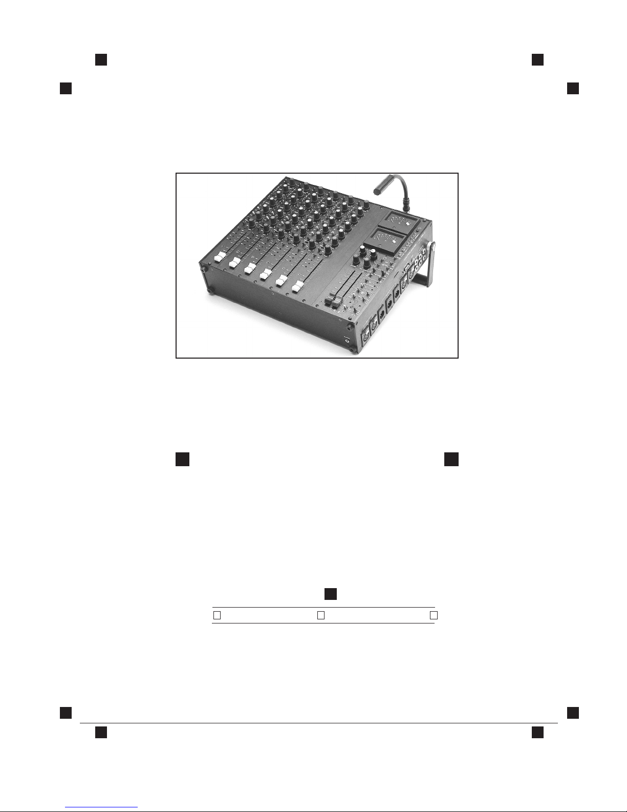
OUTPUT MODULE MODELS: CS 106+1
CS 108+1
PAGE 4 ■ JANUARY 1998 ■ REV. 3
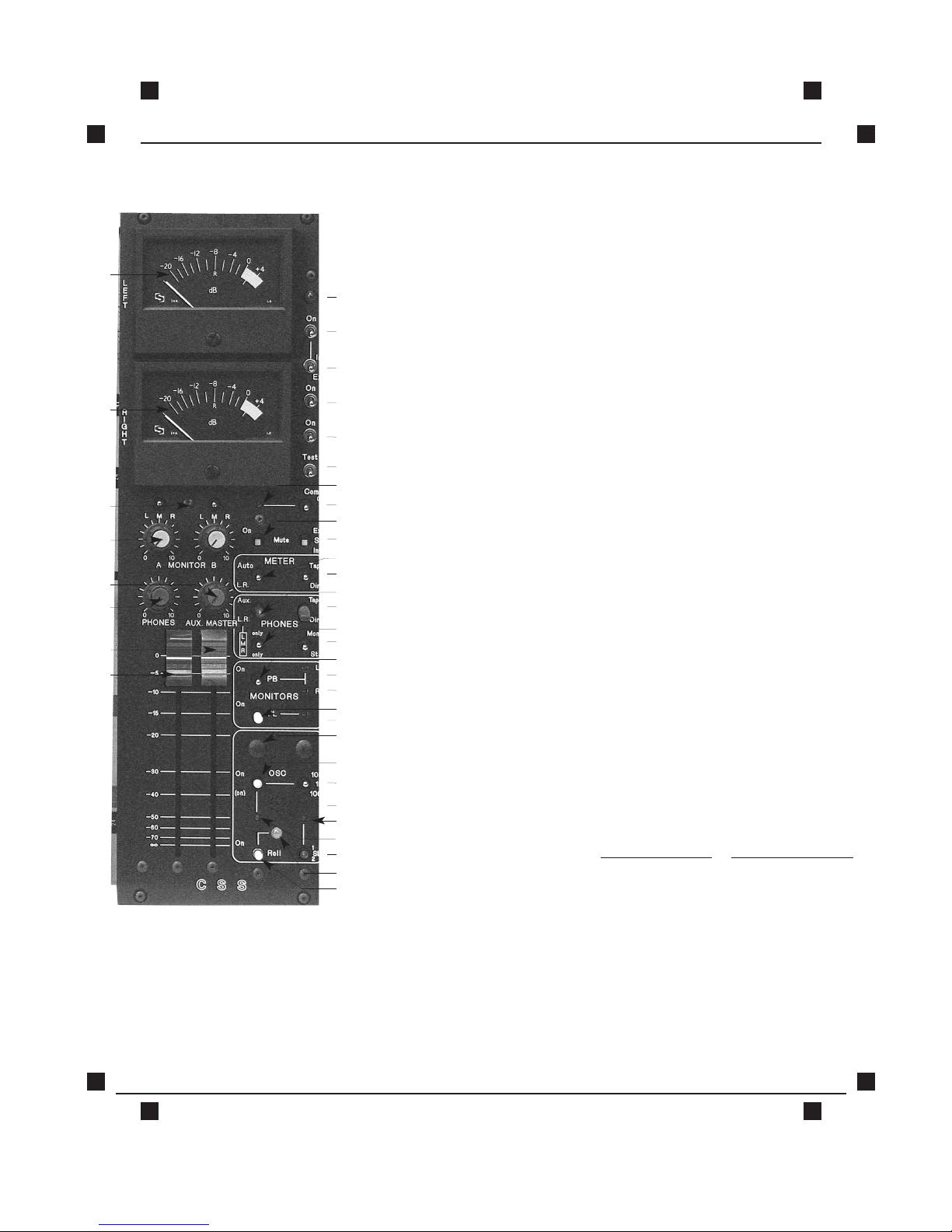
15.COMMUNICATIONS TRIMMER: To adjust level of communications signal.
16.COMMUNICATIONS ON/ OFF: Communication input is fed only to "phones." (Line level input)
(eg: Boom operator talkback or cueing)
17. MUTE ON: In "on" position both monitor A & B outputs are muted during slating
and oscillator operation. An internal circuit board switch disables
muting function to monitor A output.
18. SLATE INTERNAL /EXTERNAL: External slate mic may be connected to the slate XLR. Level is
adjusted by (34)
19. "METER" AUTO /LEFT RIGHT: In auto, the meters follow the “phones”selection. ie:Mono / stereo,
L/R, Aux., PFL, Tape/Direct, L only, R only. In the L/R position the meter
indicates left and right signals, controlled by switch #20. (Tape direct)
20. "METER" TAPE /DIRECT.
21."PHONES" AUX. /LEFT RIGHT: Auxiliary signal is fed to both left and right "phones" outputs.
22. "PHONES" TAPE /DIRECT.
23. "PHONES" LEFT,MIX, RIGHT: With switch (21) in L.R., either left only or right only or both are fed
to"phones" outputs.
24. "PHONES"MONO / STEREO.
25. "PLAYBACK: Assigns tape return to monitor A & B outputs.
26. LEFT TAPE RETURN: Level adjust for tape return.
27. RIGHT TAPE RETURN: Level adjust for tape return.
28. PRIVATE LINE: Either internal or external slate mic output is fed to monitor A output.
(Can also be assigned to monitor B, see page 16).
29. PRIVATE LINE LEVEL: Independent of slate level.
30. OSCILLATE ASSIGN: Aux only, L/R only, all outputs
31. OSC. ON: Three-position switch; Up=On Center=Off
Down=Momentarily on
Level is dependent upon master fader positions.
32. OSC. FREQUENCY SELECT: Note: Also controls the frequency of the auto end tones.
33. INTERNAL SLATE MIC.
34. SLATE LEVEL: Controls both internal and external slate levels.
35. OSCILLATOR LEVEL.
36. SLATE ON: Three-position switch; Up =On(no sub-tone) Center=Off
Down=Momentarily on (with subtone)
Also, turns remote roll on (internal switch to defeat, see page 16).
37. ROLL ON LED.
38. ROLL ON: Roll is connected to the tuchel connectors to turn on either a Nagra
4.2 or IVS or both. When the roll switch is turned to off, the recorder will
remain on for ≈1 sec.and two end tones are fed to outputs. This
function can be defeated by a dip switch inside. (See location
diagrams, page 16).
See Specifications on Page 12