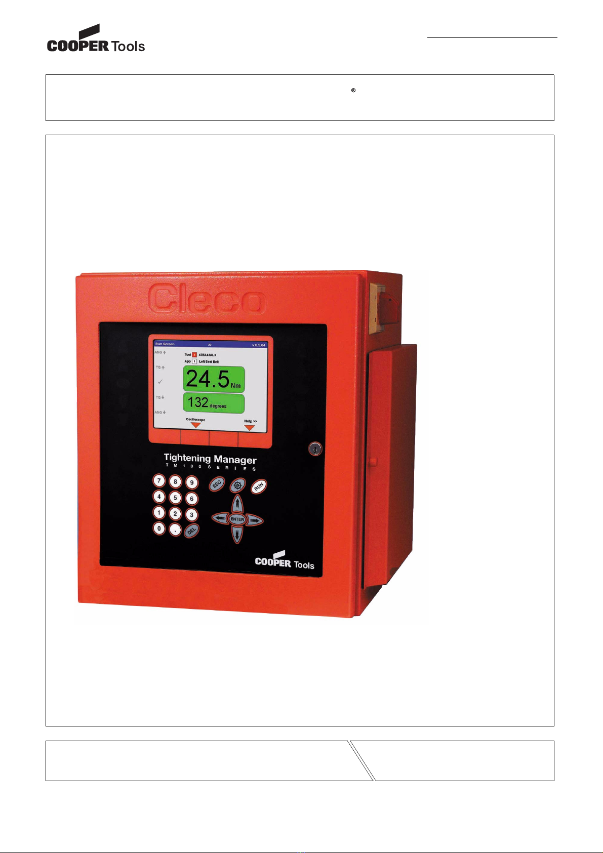
Cooper Tools Cleco TME-111 Owner's manual

Artisan Technology Group is your source for quality
new and certied-used/pre-owned equipment
• FAST SHIPPING AND
DELIVERY
• TENS OF THOUSANDS OF
IN-STOCK ITEMS
• EQUIPMENT DEMOS
• HUNDREDS OF
MANUFACTURERS
SUPPORTED
• LEASING/MONTHLY
RENTALS
• ITAR CERTIFIED
SECURE ASSET SOLUTIONS
SERVICE CENTER REPAIRS
Experienced engineers and technicians on staff
at our full-service, in-house repair center
WE BUY USED EQUIPMENT
Sell your excess, underutilized, and idle used equipment
We also offer credit for buy-backs and trade-ins
www.artisantg.com/WeBuyEquipment
REMOTE INSPECTION
Remotely inspect equipment before purchasing with
our interactive website at www.instraview.com
LOOKING FOR MORE INFORMATION?
Visit us on the web at www.artisantg.com for more
information on price quotations, drivers, technical
specications, manuals, and documentation
Contact us: (888) 88-SOURCE | sales@artisantg.com | www.artisantg.com
SM
View
Instra

Cleco
Programming Manual
PL12-1300 12/00
AMERICAS
CooperTools
P.O. Box 1410
Lexington, South Carolina 29071-1410
EUROPE
Cooper Power Tools GmbH & Co.
Postfach 30
D-73461 Westhausen
Electric Tool Control
TME-100 Series
Reference Document: PL12-1400 Parts Manual
For additional product information visit our website at http://www.coopertools.com
Artisan Technology Group - Quality Instrumentation ... Guaranteed | (888) 88-SOURCE | www.artisantg.com

Cleco
Electric Tool Control TME-100 Series
2 PL12-1300 12/00 en00d141.fm, 30.01.2001
Disclaimer:
The information and data in this document has been prepared to the best of our ability.
Nonetheless, differences between the information and the actual product cannot be
excluded with absolute certainty. Cooper Tools does not assume any liability for conse-
quential errors and damages. We likewise do not assume liability for damages resulting
from defective circuitry inside the devices supplied. Cooper Tools reserves the right, to
ammend, supplement or improve this document or the product without serving prior
notice.
Without the express approval of Cooper Tools this document must not be reproduced in
its entirity or in part by any means; it must not be converted to any type of natural or
machine readable language or be saved on data storage media of electronic, mechanic,
optical or other type.
Artisan Technology Group - Quality Instrumentation ... Guaranteed | (888) 88-SOURCE | www.artisantg.com

Electric Tool Control TME-100 Series
end14IVZ.fm, 30.01.2001 PL12-1300 12/00 3
Contents Page
Cleco
1 Getting Started 5
1.1 Safe Work Practices Symbol ................................................................ 5
1.2 Checking Your Unit............................................................................... 5
1.3 Software ............................................................................................... 5
1.4 Installing Unit ........................................................................................ 5
1.4.1 General................................................................................................. 5
1.4.2 Mounting............................................................................................... 6
1.4.3 Location Considerations....................................................................... 6
1.4.4 Source Power....................................................................................... 6
1.5 Connecting Unit.................................................................................... 6
1.5.1 General................................................................................................. 6
1.6 Energizing Unit ..................................................................................... 7
Attachment A.1 9
2 Controller Specifications 11
2.1 Understanding the Keypad .................................................................. 11
2.2 Specifications ..................................................................................... 12
2.2.1 Enclosure ........................................................................................... 12
2.2.2 Display................................................................................................ 12
2.2.3 Keypad Overlay .................................................................................. 13
2.2.4 Indicators............................................................................................ 13
2.2.5 CPU with PC/104................................................................................ 13
2.2.6 Internal AC Input Power ..................................................................... 14
2.2.7 Inernal DC Power ............................................................................... 14
2.2.8 Input / Output Connectors .................................................................. 14
3 Programming 19
3.1 Navigator Menu .................................................................................. 19
3.1.1 Basic Navigation Instructions ............................................................. 19
3.1.2 Password Function............................................................................. 19
3.1.3 Navigator Menu .................................................................................. 20
3.2 Basic Application Builder.................................................................... 21
3.2.1 Basic Parameters for Torque Control / Angle Monitor ........................ 22
3.2.2 Basic Parameters for Angle Control / Torque Monitor ........................ 22
3.2.3 Basic Application Builder Parameters ................................................ 23
3.2.4 Advanced Parameter Default Values.................................................. 23
3.3 Standard Application Builder .............................................................. 24
3.3.1 Standard Application Builder / View Stages........................................ 24
3.3.2 Standard Application Builder / Select Sequence ................................ 25
3.3.3 Standard Application Builder / Parameters......................................... 27
Artisan Technology Group - Quality Instrumentation ... Guaranteed | (888) 88-SOURCE | www.artisantg.com

Cleco
Electric Tool Control TME-100 Series
4 PL12-1300 12/00 end14IVZ.fm, 30.01.2001
3.3.4 Standard Application Builder / Advanced Parameters ........................ 31
3.3.5 Advanced Application Builder / Application Matrix .............................. 32
3.3.6 Advanced Application Builder / Inputs................................................. 33
3.3.7 Advanced Application Builder / Outputs.............................................. 34
3.3.8 Advanced / System Settings ............................................................... 36
3.4 RUN Screen ........................................................................................ 36
3.5 Oscilloscope........................................................................................ 37
3.6 Communication ................................................................................... 38
3.6.1 Communications / Printer.................................................................... 38
3.6.2 Communications / Serial Data Transmission ...................................... 39
3.7 Tool Setup ........................................................................................... 40
3.8 Tool Library.......................................................................................... 41
3.8.1 Tool Library.......................................................................................... 41
3.8.2 Tool Library / Custom .......................................................................... 42
3.9 Statistics .............................................................................................. 43
3.9.1 Statistics / Summary............................................................................ 43
3.9.2 Statistics / Chronological History......................................................... 43
3.10 Diagnostics.......................................................................................... 44
3.10.1 Inputs / Outputs................................................................................... 44
3.10.2 Tool / Calibration ................................................................................. 45
3.10.3 Tool / Voltages..................................................................................... 46
3.10.4 Tool / Angle Encoder ........................................................................... 47
3.10.5 Tool / TQ Measurement....................................................................... 48
3.10.6 Tool / Speed ........................................................................................ 48
3.10.7 Arcnet / Map........................................................................................ 49
3.10.8 Arcnet / Statistic .................................................................................. 50
3.10.9 Serial ................................................................................................... 52
3.11 Utilities................................................................................................. 53
3.11.1 Utilities / Update Software................................................................... 53
3.12 Administration ..................................................................................... 54
3.12.1 Administration / Load/Save ................................................................. 54
3.12.2 Administration / Print ........................................................................... 55
3.12.3 Administration / Password................................................................... 55
3.12.4 Administration / Date & Time .............................................................. 56
4 Statistics 57
4.1 Understanding Statistics...................................................................... 57
4.1.1 The Nature of Variation ....................................................................... 57
4.1.2 The Normal Curve............................................................................... 57
4.1.3 The Procedure .................................................................................... 58
4.1.4 System Improvement .......................................................................... 62
4.2 Statistic Symbols ................................................................................. 63
5 Glossary 65
Artisan Technology Group - Quality Instrumentation ... Guaranteed | (888) 88-SOURCE | www.artisantg.com

Electric Tool Control TME-100 Series
en01d141.fm, 30.01.2001 PL12-1300 12/00 5
Cleco
1 Getting Started
1.1 Safe Work Practices Symbol
The signal word "Warning" identifies all notes on safe work practices in this operating
instruction, alerting to hazards for life and health of people. Observe these notes and pro-
ceed with special care in the cases described. Pass all safety instructions on to other
operators. In addition to the safety instructions in this operating instruction, the general
local safety and accident prevention rules must be observed.
The signal word "Caution!" identifies all portions of this operating instruction meriting
special attention to ensure that guidelines, rules, hints and the correct work procedures
are observed; and, to prevent damage to and destruction of the machine and/or parts.
1.2 Checking Your Unit
Take the time to ensure you have the required peripheral equipment and cables necessary to
setup and run your unit. If you do not have all the necessary items, contact your distributor.
Refer to “Attachment A.1” on page 9 for illustration of your unit.
1.3 Software
Your unit has been pre-loaded with version 1.0 software and requires no additional software to
begin your fastening process. If you are interfacing your unit with an external computer, interfac-
ing software is required. Contact your distributor for the interfacing software.
1.4 Installing Unit
1.4.1 General
It is mandatory that national, state and local safety and wiring standards be followed dur-
ing installation. These standards would take precedence over any information presented
in this section.
To avoid the hazard of electrical shock or burn, the following instructions must be
adhered to. Failure to follow these instructions may also cause damage to your unit and
void existing warranties.
• Do not energize the unit until all connections have been properly made.
• Equipment must be properly grounded before applying power. Units energized by
cord and plug must be connected to an approved and properly grounded receptacle.
• All units must be energized by an isolated line.
• The unit door must always be closed and secured prior to energizing the unit.
• Ensure the power switch is in the "off" position prior to connecting the power cord.
Though it is not mandatory, the following instructions are highly recommended for the
protected operation of your unit.
• Use an isolation transformer and surge arrestor on the incoming isolated line.
• Use oversized feeder lines to reduce electrical noise and voltage drop.
!
CAUTION!
!
CAUTION!
Artisan Technology Group - Quality Instrumentation ... Guaranteed | (888) 88-SOURCE | www.artisantg.com

Cleco
Electric Tool Control TME-100 Series
6 PL12-1300 12/00 en01d141.fm, 30.01.2001
1.4.2 Mounting
Each unit is used primarily as a single tool process/controller/monitor installed in a work station
or work area. It may be wall mounted, table mounted, beam mounted, suspended overhead,
pedestal mounted or used without mounting. Always choose a stable location to avoid the possi-
bility of unit damage and/or operator injury through hitting, falling, vibration or inconvenient
mounting. All cables attached to the unit should be located and secured in a manner to avoid
potential operator and passer-by injury. As with all electrical equipment, the unit will produce
some heat and should be located so that ambient air can freely circulate around the box.
Refer to Illustration Q of the parts manual, PL12-1400 for mounting hole dimensions.
1.4.3 Location Considerations
Your unit should be located to allow access to the front panel and connectors. The unit should
be installed for unrestricted and comfortable viewing of the LCD & LED's by the operator. The
LCD menu screen, key pad and side door connectors must be readily accessible for the setup.
Dependent on the peripheral equipment purchased, the unit may be located in a remote position
but should still be accessible.
Attachment of accessories and tools should also be considered with the installation locations.
Items to be considered are:
• Location of printer (10 ft. cable maximum for the parallel interface).
• Attachment of a data collection unit, if desired.
• Attachment of redundant master transducers (less than 50 ft. is desirable).
• Attachment of remote annunciators, socket nest, or remote parameter select.
• Attachment of the unit in a network to a computer.
• Operation convenience/safety - keep cables off the floor or dangling in operator areas.
1.4.4 Source Power
Your unit, which is used as the process control and power supply for the Cleco DC electric tools,
requires a power line with 10 amp capacity at 220-240 Volts AC (50/60 Hz) for the TME-111-30.
The TME-111-15 requires a power line with 15 amp capacity at 110-130 Volts AC (50/60 Hz).
1.5 Connecting Unit
1.5.1 General
Connect all equipment to the correct input and output connectors. Refer to “Attachment A.1” on
page 9 for proper port locations.
To avoid the hazard of electrical shock or burn the following instructions must be
adhered to. Failure to follow these instructions may also cause damage to your unit and
void existing warranties.
• Ensure the power switch is in the "off" position and that the box cover is properly
secured prior to connecting power cord.
• Ensure equipment has been properly grounded before applying power.
!
Artisan Technology Group - Quality Instrumentation ... Guaranteed | (888) 88-SOURCE | www.artisantg.com

Electric Tool Control TME-100 Series
en01d141.fm, 30.01.2001 PL12-1300 12/00 7
Cleco
1.6 Energizing Unit
To avoid the hazard of electrical shock or burn the following instructions must be
adhered to. Failure to follow these instructions may also cause damage to your unit and
void existing warranties.
Upon application of power, the unit will initiate a self test. The initialization takes approximately
45 seconds.
The introduction screen shown below will be displayed for approximately 10 seconds and then
the navigator menu will be displayed.
Fig. 1-1: Introduction Screen
Fig. 1-2: Navigator Menu
!
c00276de.bmp
c00277en.bmp
Artisan Technology Group - Quality Instrumentation ... Guaranteed | (888) 88-SOURCE | www.artisantg.com

Cleco
Electric Tool Control TME-100 Series
8 PL12-1300 12/00 en01d141.fm, 30.01.2001
After the Navigator Menu is displayed, verify the Tool Memory by entering Tool Setup. If Tool
Memory is not active then select a tool using the Tool Library. Press the ship's wheel to return to
the Navigator Menu.
Once Tool Setup is complete the application needs to be programmed. To do this, go to Basic
Application Builder. From this screen torque, angle, and speed parameters must be entered for
the selected application. Press the ship's wheel to return to the Navigator Menu.
The controller is now ready to begin fastening cycles. The torque and angle data can be viewed
by pressing the Run Key. Tool and controller indicator lights will illuminate according to the
results.
Artisan Technology Group - Quality Instrumentation ... Guaranteed | (888) 88-SOURCE | www.artisantg.com

Electric Tool Control TME-100 Series
en01d141.fm, 30.01.2001 PL12-1300 12/00 9
Cleco
Attachment A.1
Fig. 1-3: Controller
Fig. 1-4: Connector Box Detail
Mounting
Bracket
Sidedoor
Assembly
Connector
Box
(see detail
below)
Double-Bit
Enclosure
LCD
Display
Indicator
Lights
Keypad
Tool Connector
Floppy Drive
Printer Power Out
Power In
Double-Bit Enclo-
sure key
Power Switch
I/O Outputs
I/O Inputs
Serial Ports (2)
Printer Port
Keyboard Port
Artisan Technology Group - Quality Instrumentation ... Guaranteed | (888) 88-SOURCE | www.artisantg.com

Cleco
Electric Tool Control TME-100 Series
10 PL12-1300 12/00 en01d141.fm, 30.01.2001
Artisan Technology Group - Quality Instrumentation ... Guaranteed | (888) 88-SOURCE | www.artisantg.com

Electric Tool Control TME-100 Series
en02d141.fm, 30.01.2001 PL12-1300 12/00 11
Cleco
2 Controller Specifications
2.1 Understanding the Keypad
The following is a brief explanation of the keypad keys. You will need to become familiar with
these keys so you can smoothly program your unit.
Soft Keys (F1-F4) - used to select functions based on the screen displayed.
ESC Key - used at any time to return back one screen or exit the edit mode.
DEL Key - used to delete a numerical value on the LCD screen.
Arrow Keys - used to move the orange highlight around the screen.
ENTER Key - used to accept an answer/value on the LCD screen.
Ships Wheel - used at any time to return to the navigator menu.
Run - used at any time to return to Run Screen.
Soft Keys
Ship´s Wheel
Artisan Technology Group - Quality Instrumentation ... Guaranteed | (888) 88-SOURCE | www.artisantg.com

Cleco
Electric Tool Control TME-100 Series
12 PL12-1300 12/00 en02d141.fm, 30.01.2001
2.2 Specifications
2.2.1 Enclosure
* Mounting plate adds weight of 7 lbs / 3.2 kg and depth of 1.62 in / 41.1 mm
• Designed for NEMA 13/IP54 rating
• Lockable front door for customer specific key requirements
• Lockable 3-phase power switch
• Side door for connector/cable protection
• Removable Mounting Plate
• Removable, fully operational internal chassis
• Conductive front door gasket and lip to meet EMI regulations
• Orange textured powder coat
2.2.2 Display
• 7.7 in Passive Matrix Color LCD Module
• 640 x 480 resolution
• CCFT backlight
• Contrast and Brightness control
Model Weight* Width Height Depth
lb kg in mm in mm in mm
TME-111 80 36.4 16.5 419.1 17.5 444.5 12.3 312.4
Artisan Technology Group - Quality Instrumentation ... Guaranteed | (888) 88-SOURCE | www.artisantg.com

Electric Tool Control TME-100 Series
en02d141.fm, 30.01.2001 PL12-1300 12/00 13
Cleco
2.2.3 Keypad Overlay
2.2.4 Indicators
5 Highly visible indicators
• 2 red groupings
• 1 green grouping
• 2 amber groupings
• Each grouping contains 12 high intensity LED´s @ 30 mcd each
2.2.5 CPU with PC/104
Minimum Requirements
• Pentium 133 Mhz
• 32 MB DRAM
• 16 MB DiskonChip
• 4 serial ports
• 1 parallel port
• Ethernet 100-Base T
• PC Keyboard input
• PC/104 Bus
• Floppy interface
• LCD/Flat Panel controller
Key Definitions
Key Description
0-9 Numbers 0-9
. Decimal point
DEL Delete
ESC Escape
Navigator Menu
RUN Run Screen
Up Arrow
Down Arrow
Left Arrow
Right Arrow
ENTER Enter
Orange Border 4 Soft Keys
Artisan Technology Group - Quality Instrumentation ... Guaranteed | (888) 88-SOURCE | www.artisantg.com

Cleco
Electric Tool Control TME-100 Series
14 PL12-1300 12/00 en02d141.fm, 30.01.2001
Arcnet PC/104 board
• Arcnet communication
• 4 +24 V inputs
• 12 +24 V outputs
• 24-position keypad decoder
• Battery-Backed SRAM, 1 MB
External I/O PC/104 board
• 8 optically isolated inputs
• 8 relay outputs
• Switching levels to meet IEC-1131-2
2.2.6 Internal AC Input Power
• Selectable 115 VAC @15 A or 230 VAC @ 10 A, +/-5% on all voltages
• Internal fuse
• Fault current circuit-breaker (10 mA)
• Isolation Transformer 4.5 kVA peak, meets VDA 0570 norm
2.2.7 Inernal DC Power
• Input: 85 VAC-264 VAC
• Output: +5 VDC @ 5 A, +12 VDC @ 1 A, +24 VDC @ 3 A, +/-5% on all voltages
• 110 W capability without a fan
• MTBF->20,000 hours
2.2.8 Input / Output Connectors
Tool Connector Matrix MS83723R/2028N
Serial (2) 9-pin Male D-Shell
Parallel 25-pin Female D-Shell
Keyboard Mini 6-DIN
Inputs (+24 V) Phoenix MSTBV 2,5/12-GF-5,08 Order No. 1777170
Outputs Phoenix ICV 2,5/12-GF-5,08 Order No. 1825792
Floppy 3.5in 1.44 MB
AC Power Input Standard male receptacle
AC Power Output Standard female receptacle
Artisan Technology Group - Quality Instrumentation ... Guaranteed | (888) 88-SOURCE | www.artisantg.com

Electric Tool Control TME-100 Series
en02d141.fm, 30.01.2001 PL12-1300 12/00 15
Cleco
Tool
Pin # Description Value
1 +Excitation +12 V +/- .05 V
2 -Excitation 0 V
3 Drehmomentsignal 0 to +5 V
4 0 V Drehmomentsignal 0 V
5 Tool Memory TXD - -3 V to +3 V
6 Tool Memory TXD + -3 V to +3 V
7 Tool Memory RXD - -3 V to +3 V
8 Tool Memory RXD + -3 V to +3 V
9 Resolver Carrier R1 7 VAC
10 Resolver Carrier R2 0 VAC
11 Resolver Cosine S1 7 VAC
12 Red LED 0 to +24 V
13 Signal GND 0 V
14 Yellow LED 0 to +24 V
15 Motor PE 0 V
16 Start Switch 0 to +24 V
17 Reverse Switch 0 to +24 V
18 +24V +24 V
19 Motor Phase C 0 to 300 V
20 Transducer Calibration 0 to +5 V
21 Temperature Sensor + 0 to +5 V
22 Temperature Sensor - 0 to +5 V
23 Motor Phase B 0 to 300 V
24 Resolver Sine + S2 7 VAC
25 Resolver Cosine S3 0 VAC
26 Resolver Sine S4 0 VAC
27 Motor Phase A 0 to 300 V
28 Green LED 0 to +24 V
Housing PE 0 V
Serial
Pin # Description Value
1 DCD -25 V to +25 V
2 RxD -25 V to +25 V
3 TxD -25 V to +25 V
4 DTR -25 V to +25 V
5GND0V
6 DSR -25 V to +25 V
7 RTS -25 V to +25 V
Artisan Technology Group - Quality Instrumentation ... Guaranteed | (888) 88-SOURCE | www.artisantg.com

Cleco
Electric Tool Control TME-100 Series
16 PL12-1300 12/00 en02d141.fm, 30.01.2001
8 CTS -25 V to +25 V
9 RI -25 V to +25 V
Parallel
Pin # Description Value
1 Strobe 0 to +5 V
2 Data 0 0 to +5 V
3 Data 1 0 to +5 V
4 Data 2 0 to +5 V
5 Data 3 0 to +5 V
6 Data 4 0 to +5 V
7 Data 5 0 to +5 V
8 Data 6 0 to +5 V
9 Data 7 0 to +5 V
10 Acknowledge 0 to +5 V
11 Busy 0 to +5 V
12 Paper Out 0 to +5 V
13 Select Out 0 to +5 V
14 Auto Feed 0 to +5 V
15 Error 0 to +5 V
16 Initialize 0 to +5 V
17 Select In 0 to +5 V
18 Gnd 0 V
19 Gnd 0 V
20 Gnd 0 V
21 Gnd 0 V
22 Gnd 0 V
23 Gnd 0 V
24 Gnd 0 V
25 Gnd 0 V
Keyboard
Pin # Description Value
1 Data 0 to +5 V
2N/CN/A
3 Gnd 0 V
4 Power 0 to +5 V
5Clock0to+5V
Serial
Artisan Technology Group - Quality Instrumentation ... Guaranteed | (888) 88-SOURCE | www.artisantg.com

Electric Tool Control TME-100 Series
en02d141.fm, 30.01.2001 PL12-1300 12/00 17
Cleco
Inputs
Pin # Description Value
1 +24 V (Output) +24 VDC
2 Input 0 0 to +24 V
3 Input 1 0 to +24 V
4 Input 2 0 to +24 V
5 Input 3 0 to +24 V
6 Input 4 0 to +24 V
7 Input 5 0 to +24 V
8 Input 6 0 to +24 V
9 Input 7 0 to +24 V
10 Input Common (Input) 0 V
11 Signal Gnd (Output) 0 V
12 Spare N/A
Outputs
Pin # Description Value
1 +24 V (Output) +24 VDC
2 Output Common (Output) 0 to 30 V
3 Output 0 0 to 30 V
4 Output 1 0 to 30 V
5 Output 2 0 to 30 V
6 Output 3 0 to 30 V
7 Output 4 0 to 30 V
8 Output 5 0 to 30 V
9 Output 6 0 to 30 V
10 Output 7 0 to 30 V
11 Signal Gnd (Output) 0 V
12 Spare N/A
Artisan Technology Group - Quality Instrumentation ... Guaranteed | (888) 88-SOURCE | www.artisantg.com

Cleco
Electric Tool Control TME-100 Series
18 PL12-1300 12/00 en02d141.fm, 30.01.2001
Artisan Technology Group - Quality Instrumentation ... Guaranteed | (888) 88-SOURCE | www.artisantg.com

Electric Tool Control TME-100 Series
en03d141.fm, 30.01.2001 PL12-1300 12/00 19
Cleco
3Programming
3.1 Navigator Menu
Fig. 3-1: Navigator Menu
3.1.1 Basic Navigation Instructions
Each field in a screen is selectable with an orange highlight using the 4 arrow keys and Enter.
Upon entering a screen the top left most field is always highlighted. The Navigator key (ship's
wheel) will always return the user to the Navigator Menu. At the bottom of the screen 4 soft keys
are available. These functions will change from screen to screen. In some cases the screen
label will contain the (>>) character to indicate more functions are available when the key is
pressed.
To edit a textbox the user can use 0-9 or the DEL keys. To exit the edit mode the user can press
the arrow keys to move the highlight or press the ESC key. The ESC key will return the original
value.
In order to describe the soft key functions the left soft key is referred to as F1, center left soft key
F2, center right soft key F3 and right soft key F4. They are located in the orange display border.
F4 always functions as Help for that screen.
Applications are selectable 1-8.
Stages are selectable 1-6.
3.1.2 Password Function
If the user exits a section with programmable data (Basic, Standard, Advanced, Communica-
tions, Tool Setup) that has been changed, then the password entry dialog will be displayed. If no
password is activated, then only the confirm entry in the password dialog is displayed. Once the
password has been entered, it must be entered each time an appropriate screen is exited.
c00277en.bmp
Artisan Technology Group - Quality Instrumentation ... Guaranteed | (888) 88-SOURCE | www.artisantg.com
This manual suits for next models
1
Table of contents
Popular Control Unit manuals by other brands

Pepperl+Fuchs
Pepperl+Fuchs WCS-CG310 manual

Satel
Satel KNX-BIN24 manual

Newhaven Display International
Newhaven Display International NHD-10.1-HDMI-A-RSXV user guide

Sentiotec
Sentiotec K Series Instructions for installation and use

ICP DAS USA
ICP DAS USA GTM-204M-4G quick start

Silex technology
Silex technology SX-550 Developer's reference guide