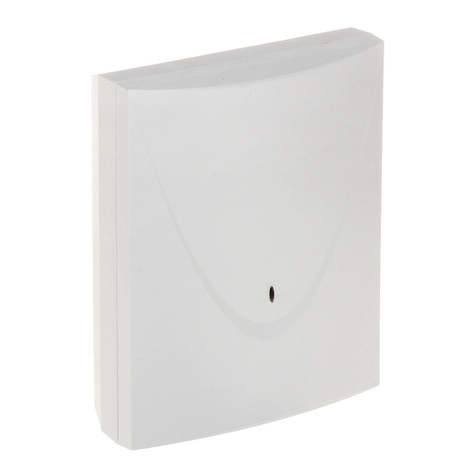
Satel KNX-BIN24 User manual

KNX-BIN24
Universal binary input module
Firmware version 1.01 knx-bin24_en 10/19
SATEL sp. z o.o. • ul. Budowlanych 66 • 80-298 Gdańsk • POLAND
tel. +48 58 320 94 00
www.satel.eu

IMPORTANT
The device should be installed by qualified personnel.
Prior to installation, please read carefully this manual in order to avoid mistakes that can lead
to malfunction or even damage to the equipment.
Changes, modifications or repairs not authorized by the manufacturer shall void your rights
under the warranty.
SATEL aims to continually improve the quality of its products, which may result in changes in
their technical specifications and software. Current information about the changes being
introduced is available on our website.
Please visit us at:
http://www.satel.eu
The declaration of conformity may be consulted at www.satel.eu/ce
The following symbols may be used in this manual:
- note,
- caution.

SATEL KNX-BIN24 1
CONTENTS
1. Features ..............................................................................................................................2
2. Description...........................................................................................................................3
2.1 Enclosure ................................................................................................................................... 4
3. Installation ...........................................................................................................................4
3.1 Wiring diagram ........................................................................................................................... 5
4. Configuring the module .......................................................................................................5
4.1 Schematic diagram of the module.............................................................................................. 7
4.2 Starting configuration ................................................................................................................. 7
4.3 Configuring global parameters ................................................................................................. 10
4.4 Configuring channels................................................................................................................ 10
4.4.1 Physical channels...........................................................................................................................10
4.4.2 Virtual channels ..............................................................................................................................12
4.4.3 Logic channels................................................................................................................................13
4.4.4 Timer channels ...............................................................................................................................15
4.5 Configuring function blocks ...................................................................................................... 17
4.5.1 Switch .............................................................................................................................................19
4.5.2 Edge (monostable switch) ..............................................................................................................21
4.5.3 Dimmer ...........................................................................................................................................23
4.5.4 Shutter ............................................................................................................................................26
4.5.5 Sequence........................................................................................................................................29
4.5.6 Counter ...........................................................................................................................................34
4.5.7 Scene..............................................................................................................................................37
4.6 Communication objects ............................................................................................................ 37
4.6.1 Virtual inputs...................................................................................................................................37
4.6.2 Communication objects of function blocks .....................................................................................38
4.7 Configuration examples............................................................................................................ 45
4.7.1 One-channel control of several function blocks..............................................................................45
4.7.2 Using timer channel........................................................................................................................46
4.7.3 Using virtual and logic channels.....................................................................................................47
5. Specifications ....................................................................................................................49
6. Appendix............................................................................................................................50
6.1 4-bit telegrams for dimming DOWN/UP ................................................................................... 50
6.2 4-bit telegrams for shutter control.............................................................................................50
2 KNX-BIN24 SATEL
KNX-BIN24 is a universal module of KNX binary inputs that enables signals from outside
KNX installation to be converted into control telegrams for other devices on the bus. These
signals may be generated by conventional ON/OFF buttons (to operate lighting, etc.), reed
switches or sensors for registering various types of physical quantities (e.g. temperature).
The module has eight physical inputs which allow it to handle 8 independent signals
ranging from 0 to 30 VDC/AC. Each physical input in the module corresponds to one
physical channel (A – H).
1. Features
Communication with the KNX bus via integrated bus connector.
Definable channel polarity (NO / NC).
Configurable time of short / long button press.
Virtual channels for receiving telegrams from other KNX bus devices.
Virtual logic channels for creating logical links between module channels.
Virtual timer channels for creating time links.
Possibility to define 20 function blocks that perform one of the available functions:
switch / value transmitter,
edge response,
dimmer,
shutter controller,
switching sequence,
counter,
scene controller.
Possibility to control each function block using any channel.
Control of several function blocks using one channel.
Control of lighting and shutters using 1 or 2 buttons (channels).
Ability to call a scene from any channel by using 8-bit commands.
Manual operation of physical channels status by using buttons on the enclosure.
LEDs to indicate status of physical channels.
Module configuration by using ETS program.
Mounted in distribution boxes, on DIN rail (35 mm).

SATEL KNX-BIN24 3
2. Description
physical input terminals.
green LEDs indicating the status of module physical channels. One channel status LED
is assigned to each channel:
ON – channel is ON,
OFF – channel is OFF.
buttons to manually switch the state of physical channels (to simulate changes on
physical inputs).
Each button can work as monostable or bistable switch. How the button will operate
can be defined separately for each channel in ETS program, “Physical channels” tab.
red LED – is ON when physical address is being set using the ETS program. Setting the
address may be activated remotely from the ETS program or manually, using the
button on the enclosure.
programming button (used when setting the physical address).
terminal to connect KNX bus.

4 KNX-BIN24 SATEL
2.1 Enclosure
The module takes up 4 units on the 35 mm DIN rail.
3. Installation
Disconnect power before making any electrical connections.
The module is designed for indoor installation, in spaces with normal air humidity, e.g. in
distribution boxes on 35 mm DIN rail.
1. Mount the module on the mounting rail.
2. Connect the devices to the terminals. For designations of the terminals see the front
panel.
All connections should be made as recommended in section “Wiring diagram”.
3. Use the connection terminal to connect the KNX bus cable to the module.
The module is supplied with voltage from the KNX bus and requires no additional
power supply.
4. Connect a computer running ETS program to the KNX bus and configure the module.
To configure the module, you will require a computer running the ETS program version
5.5 or newer, provided with USB or Ethernet (TCP/IP) connector. The SATEL ETS
application file, which can be downloaded from www.satel.eu/ets, must be imported
into the program.
For detailed information on how to configure the module, refer to section “Configuring the
module”.

SATEL KNX-BIN24 5
3.1 Wiring diagram
The KNX-BIN24 module has two independent circuits. Each circuit includes four inputs: A, B,
C, D – circuit 1, and E, F, G, H – circuit 2. DC or AC voltage can be applied to each module
input, allowable input voltage ranging from 0 to 30 V.
Input voltage from 0 to 4 V is interpreted as “0” and voltage from 9 to 30 V – as “1”. To
avoid malfunctioning of the module, voltage ranging from 4 to 9 V must not be applied
to any input.
Each module input can be connected to a different current source, but one type of voltage,
either DC or AC, must be applied to inputs belonging to one circuit.
Fig. 3 shows some examples of module connection:
I – voltage from one source, AC or DC, is applied to all inputs of the module,
II – voltage from two different sources is applied to inputs of circuits 1 and 2 (DC voltage is
applied to inputs of one circuit, and AC voltage to inputs of the other circuit),
III – voltage from different sources is applied to inputs within one circuit (DC voltage is
applied to inputs of one circuit, and AC voltage to inputs of the other circuit).
4. Configuring the module
Working parameters of the module are defined in the ETS program (version 5.5 or higher).
The tabs for defining individual parameters are built dynamically. Depending on the selected
options, further parameters may be displayed in the tabs or further tabs may be displayed
when defining parameters. Moving the cursor over the selected parameter will display
a tooltip with default value or value range for that parameter.

6 KNX-BIN24 SATEL
Configuring the module can be divided into three steps:
Configuring global parameters.
Configuring channels.
Configuring function blocks.
There are four channel groups in the module:
physical – convert electric signals from physical inputs (terminals) into events that can be
handled by the module (8 channels), see “Physical channels”.
virtual – convert telegrams received from other KNX bus devices and the module function
blocks into events that can be handled by the module (8 channels), see “Virtual
channels”.
logic – special virtual channels that enable logical links to be created between the module
channels (4 channels), see “Logic channels”.
timer – special virtual channels that enable the status of channels of the module or KNX
bus devices (4 channels) to be cyclically switched, see “Timer channels”.
The following events can be generated in each channel:
rising edge,
falling edge,
button short pressing,
button long pressing (holding).
Additionally, each channel store information about its own current state (Off / On).
You can define 20 function blocks in the module. The function block can execute one on the
following functions:
switch / value transmitter,
edge response,
dimmer,
shutter controller,
switching sequence,
counter,
scene controller.
Each function block can be controlled by using events from any module channel, and events
from one channel can be used to control several function blocks at the same time.
Function blocks executing different functions can be controlled by events from one
channel.
Events generated in the module channels can also be control signals for the timer channels,
and the state of channels can be linked in the logic function defined in the logic channel. Next
sections present a schematic diagram of the module (Fig. 4) and a diagram of the starting
configuration (Fig. 5) that was defined in the module ETS application. Section “Configuration
examples” shows an example of configuration in which one channel is used to control several
function blocks at the same time as well as examples of using the virtual, logic and timer
channels.

SATEL KNX-BIN24 7
4.1 Schematic diagram of the module
* function: switch / value transmitter, edge response, dimmer, shutter controller, switching
sequence, counter, scene controller.
4.2 Starting configuration
In the ETS application for configuring the module working parameters, the starting
configuration has been defined, including the working parameters of physical channels
and 8 function blocks that execute the switch function (Function block 1…8: switch). If

8 KNX-BIN24 SATEL
the module is programmed without modifying the starting configuration, each physical
channel of the module will control one function block executing the bistable switch
function (ON / OFF).
The module starting configuration can be modified by the user at will.
Presented below (Fig. 5) is a block diagram with starting configuration in which physical
channels of the module receive electric signals from the physical inputs and convert them
into events handled by the module. In the starting configuration, short button press events
generated in each physical channel of the module (A – H) control one function block
(Function block 1…8: switch), and thus “ON” / “OFF” telegrams are sent to the KNX bus.

10 KNX-BIN24 SATEL
4.3 Configuring global parameters
The main working parameters of the module are defined in the “Global” tab, which is
presented below.
Startup delay – time period by which the module startup will be delayed after power-on
(0 - 65535 [seconds]). Value “0” will disable the delay.
During the delay period, the telegram handling is stopped and the channels do not change
their state. The module sends no telegrams to the KNX bus. After the delay expires, the
telegrams will be sent and the channel state will be set according to the parameters
defined. If any telegrams from the bus with queries about the status of communication
objects reach the module during the delay period, they will be stored. Replies to these
telegrams are sent after expiry of the delay time.
The startup delay may be used to reduce load on the KNX bus and supply circuit after
power-on.
Number of virtual inputs – the number of “Virtual input A…H” 1-bit communication objects
that will be enabled in the module (0 – 8). The objects allow the module to receive
telegrams from the KNX bus (see “Virtual channels”).
4.4 Configuring channels
You can configure the channels in the “Channels” tab. Physical, virtual, logic and timer
channels are grouped in separate tabs. Configuring is described based on the first channel
from each group, because it is done in the same way for all channels from the given group.
4.4.1 Physical channels
Working parameters of the physical channels have been defined in the starting
configuration, which is saved in the ETS module configuring application. If the module
has been programmed without modifying the starting configuration, the physical
channels will have the following parameters: Polarity = NO; Time of button short
pressing = 100 ms; Time of button long pressing = 1000 ms; Behavior of manual
override button = Monostable.
One physical channel (A – H) is assigned to each physical module input. A change of electric
input signal (UN0 / UN1) will change the channel logic state (0 / 1). These changes in the
channel will generate events supported by the module. The event generating scheme is
shown in Fig. 6, where: change of the channel logic state from 0 to 1 = rising edge, from 1 to
0 = falling edge, TS– short button press duration, TL– long button press duration.
For each physical channel you can define its polarity (NO / NC), short and long button press
duration and behavior of manual channel status override button.

SATEL KNX-BIN24 11
Description of parameters

12 KNX-BIN24 SATEL
Polarity – defines how the channel logic state will change in response to a signal change on
physical input (Fig. 6):
Polarity Input signal Channel logic state
UN0 0
NO UN1 1
UN0 1
NC UN1 0
Time of button short pressing (n * 10 ms) – time that must elapse during a change of the
channel logic state from “0” to “1” and back to “0” for short button press to be generated in
the channel – see Fig. 6 (0 – 255; default = 10). Button press duration is calculated as
product of n * 10 ms, where: n = value entered in the field.
Time of button long pressing (n * 10 ms) – time that must elapse during a change of the
channel logic state from “0” to “1” and back to “0” for long button press to be generated in
the channel – see Fig. 6 (0 – 255; default = 100). Button press duration is calculated as
product of n * 10 ms, where: n = value entered in the field.
Behavior of manual override button – behavior of the channel state manual override
button (to simulate changes on the physical input):
Monostable – pressing the button changes the channel state, releasing the button
restores the previous state of the channel.
Bistable – pressing the button changes the channel state.
4.4.2 Virtual channels
Enable events supported by the module to be generated based on the telegrams received
from the KNX bus. The channel virtual input can be the “Virtual input A…H” 1-bit
communication object or 1-bit function block object that has been activated in the program,
e.g. the “FB 1: switch – Short pressing (1-bit)” object. Changing the state of the object (virtual
input) generates events in the channel according to the scheme below:
rising edge – when state changes from “0” to “1”.
falling edge – when state changes from “1” to “0”.
button short pressing – on receiving a telegram, regardless of whether or not it will
change the object state.
button long pressing – receiving a telegram by the object triggers countdown of that
object monitoring time (“Time of button long pressing” field). If the object receives no other
telegram within that time period, a long press event is generated in the channel.
For each virtual channel, you can select a virtual input (communication object) and define the
channel polarity as well as long button press duration.

SATEL KNX-BIN24 13
Description of parameters
Polarity – defines how the channel logic state will change in response to a change of state of
the communication object selected in the field “Channel virtual input”:
Polarity Object (input) state Channel logic state
0 0
NO 1 1
0 1
NC 1 0
Time of button long pressing – object monitoring time selected in the “Virtual input” field
(0 - 65535 [seconds]). If value “0” is selected, the long button press event cannot be
generated in the channel.
Channel virtual input – select the communication block that will be a virtual input of the
channel (changing the object state will generate channel event). You can select the
“Virtual input A…H” object or communication object of function block which has been
activated in the program (e.g. “FB 1…20: switch”).
Only a 1-bit communication object may be a virtual channel input.
4.4.3 Logic channels
You can define 3 logical links in each logic channel. Using the available logic functions AND,
NAND, OR, NOR, XOR, XNOR, you can create a combination function in which the state of
different module channels can be linked (see Fig. 7, where: “Input 1…4” = state of physical /
virtual / logical / timer channel). Changing the logical value (0 / 1) resulting from these links
changes the channel logic state. These changes generate the channel events which are
handled by the module. The event generating scheme is shown in Fig. 8, where: change in
channel logic state from 0 to 1 = rising edge, from 1 to 0 = falling edge, TS– short button
press duration, TL– long button press duration.

14 KNX-BIN24 SATEL
Because the channel logic states instead of events generated in the channels are the
input signals for logic functions, the logic channel can respond more quickly to
changes occurring in these channels.

SATEL KNX-BIN24 15
Description of parameters
Polarity – defines how the channel logic state will change in response to the logic function
result (Fig. 8):
Polarity Logic function result Channel logic state
0 0
NO 1 1
0 1
NC 1 0
Time of button short pressing (n * 10 ms) – time that must elapse when changing the
channel logic state from “0” to “1” and back to “0” for the short button press event to be
generated in the channel – see Fig. 8 (0 – 255; default = 5). The press duration is
calculated as product n * 10 ms, where: n = value entered in the field.
Time of button long pressing (n * 10 ms) – time that must elapse when changing the
channel logic state from “0” to “1” and back to “0” for the long button press event to be
generated in the channel – see Fig. 8 (0 – 255; default = 100). The press duration is
calculated as product n * 10 ms, where: n = value entered in the field.
Number of logic functions – the number of logic functions used in the channel (default = 1,
maximum = 3). Selecting values 2 and 3 will display in the tab further fields for defining the
logic functions 2 and 3.
Logic function 1/2/3 – type of function (AND / NAND / OR / NOR / XOR / XNOR).
Input 1/2/3/4 – channel whose state will be input value for logic function (Physical channel
A…H / Virtual channel A…H / Logic channel A…D / Timer channel A…D).
4.4.4 Timer channels
They generate events in defined time intervals which makes it possible to cyclically switch the
state of other devices on the KNX bus. Each timer channel switches its state “0” / “1” (ON /
OFF) cyclically. The time of one cycle Tcis defined in the program as a sum of times defined
in the fields “Timer ON duration” TON and “Timer OFF duration” TOFF, whereas the maximum
number of cycles Lcwhich will turn off the timer is defined in the “Timer cycles count” field.
You can select in the program the channel and a few events to control the timer channel.

16 KNX-BIN24 SATEL
Occurrence of the first event of this pair in the control channel will enable the timer channel,
and the second event may disable the timer channel before the maximum number of cycles
Lcis reached (see Fig. 9, where: Lc= 5; control pair = short and long press of button). In the
“Timer autostart on bus recovery” field, you can define whether the timer channel is to be
enabled immediately on starting the module, or only after the selected event is generated in
the control channel.
Changing the timer channel state will generate in the channel events that are handled by the
module cyclically. The event generating diagram is shown in Fig. 9, where: state change
from 0 to 1 = rising edge, and from 1 to 0 = falling edge.
A long button press event can only be generated in the channel, when the “Yes” option is
selected for the “Long pressing at the end” parameter, and the value defined in the field
“Timer cycles count” field is higher than zero.
To enable synchronization with the other module channels and other devices on
the KNX bus, the timer channels work in much the same way as the physical
channels, changing their state from OFF to ON etc. The difference between the
physical channels and the timer channels is that the latter change their state in defined
time intervals.

SATEL KNX-BIN24 17
Description of parameters
Timer ON duration – the time for which the channel will be enabled during the cycle
(0 - 30000 [seconds]).
Timer OFF duration – the time for which the channel will be disabled during the
cycle (0 - 30000 [seconds]).
Timer cycles count – the number of cycles after which the timer will be disabled (0 – 255). If
you select “0”, the timer will not be disabled (no long button press event will be generated
in the channel).
Timer control event pair – you can select the pair of events to control the timer. Occurrence
of the first event from the pair in the channel selected in the “Timer trigger channel” field
will enable the timer, and the second one will disable it. You can select:
Button short pressing / Button long pressing
Rising edge / Falling edge
Timer trigger channel – the channel whose events selected in the “Timer control event pair”
field will enable / disable the timer channel (Physical channel A…H / Virtual channel A…H
/ Logic channel A…D / Timer channel A…D).
Timer autostart on bus recovery – response of the channel to the bus power supply
restoration (No / Yes). If you select “Yes”, the timer channel will be enabled immediately
on starting the module.
Long pressing at the end – if you select “Yes”, a long button press event can be generated
in the channel after the last cycle – disabling the timer (No / Yes). The event will only be
generated, if the value defined in the “Timer cycles count” field is higher than zero.
4.5 Configuring function blocks
20 function blocks with unique numbers from 1 to 20 can be defined in the module. The
function block can be enabled in the “General” tab (that can be seen after opening the
“Function blocks” tab), by selecting one of the following functions: switch/value transmitter,
edge response, dimmer, shutter controller, switching sequence, counter, scene controller, for
the block with the given number (“Function block 1…20” field). For each enabled function

18 KNX-BIN24 SATEL
block, communication objects are enabled (the number of objects depends on the selected
function). A tab is displayed for configuration of the block (e.g. “1: Switch”) and linking it to the
channel or channels that will be used to control it (each function block can be controlled by
using events from any channel, and events from one channel can be used do control several
function blocks at the same time – see “Configuration examples”).
In the starting configuration of the module (ETS application file), 8 function blocks have
been defined that execute the switch function and are controlled by the short button
press events, activated in the physical channels of the module (A...H) - see “Starting
configuration”.
Shown below is the “General” tab for enabling functions in the module.
Number of function blocks – number of the function blocks that can be enabled in the
module (0…20, default = 8, maximum = 20). The number of displayed “Function block
1…20” fields depends on selected value.
Function block 1…20 – you can select the function to be executed by the block:
Not used – the function block will not be used.
Switch – functionality of bistable switch or value transmitter. Selecting this function will
enable the “FB 1…20: switch – Short press (1-bit)” communication object and display
the “1…20: Switch” tab.
Edge – the rising edge / falling edge events are used to control switching. Selecting this
function will enable the “FB 1…20: edge – Rising / falling (1-bit)” communication object
and display the “1…20: Edge” tab.
Dimmer control – for stepless control of lighting. Selecting this function will enable the
“FB 1…20: dimmer – Switch” and “FB 1…20: dimmer – Dim relative” communication
objects and display the “1…20: Dimmer” tab.
Shutter control – for stepless control of roller shutter. Selecting this function will enable
the “FB 1…20: shutter – Move up/down” and “FB 1…20: shutter – Stop/step up/down”
communication objects and display the “1…20: Shutter” tab.
Switching sequence – sequentially switches the 1-bit communication objects on the KNX
bus. Selecting this function will enable the “FB 1…20: sequence – Object 1” and “FB
1…20: sequence - Object 2” communication objects and display the “1…20: Sequence”
tab.
Counter – counts the events generated in the module channels. Selecting this function will
enable the communication objects “FB 1…20: counter: - Current value”, “FB 1…20:
Other manuals for KNX-BIN24
1
Table of contents
Other Satel Control Unit manuals

Satel
Satel ETHM-1 Plus User manual

Satel
Satel GSM-4S User manual

Satel
Satel CA-64 PTSA User manual

Satel
Satel ACCO Series User manual

Satel
Satel MZ-1 User manual

Satel
Satel GSM LT-1S User manual

Satel
Satel GSM LT-1S User manual

Satel
Satel VMG-16 User manual

Satel
Satel INT-GSM User manual

Satel
Satel INT-VG User manual