Cooper Greengate TSW-MV-W User manual

INS #
Brand Logo
reversed out of
black
INS #
Installation Instructions Greengate
Risk of Fire, Electrical Shock, Cuts or other Casualty Hazards- Installation and maintenance of this product
must be performed by a qualified electrician. This product must be installed in accordance with the applicable
installation code by a person familiar with the construction and operation of
the product and hazards involved.
Before installing or performing any service, the power MUST be turned OFF at the branch circuit breaker. According
to NEC 240-83(d), if the branch is used as the main switch for a fluorescent lighting circuit,
the circuit breaker should be marked with “SWD”. All installations should be in compliance with the National Electric
Code and all state and local codes.
Risk of Fire and Electric Shock- Make certain power is OFF before starting installation or attempting any
maintenance. Disconnect power at fuse or circuit breaker.
Risk of Burn- Disconnect power and allow fixture to cool before handling or servicing.
Risk of Personal Injury- Due to sharp edges, handle with care.
Failure to comply with these instructions may result in serious injury (including death) and property
damage.
DISCLAIMER OF LIABILITY: Cooper Lighting Solutions assumes no liability for damages or losses of any kind that may arise
from the improper, careless, or negligent installation, handling or use of this product.
IMPORTANT: Read carefully before installing product. Retain for future reference.
NOTICE: Product/component may become damaged and/or unstable if not installed properly.
Note: Specifications and dimensions subject to change without notice.
NOTE REGARDING COMPACT FLUORESCENT LAMPS:The life of some compact fluorescent lamps (CFLs) is shortened by
frequent automatic or manual switching. Check with CFL and ballast manufacturer to determine the effects of cycling.
ATTENTION Receiving Department: Note actual fixture description of any shortage or noticeable damage on delivery receipt.
File claim for common carrier (LTL) directly with carrier. Claims for concealed damage must be filed within 15 days of delivery.
All damaged material, complete with original packing must be retained.
Digital Wall Switch Timer 120/277 VAC- Model# TSW-MV-W
NOTICE: All new wiring must be fully verified before applying power.
NOTICE: Designed for indoor installation and use only. Dry location rated.
NOTICE: For use with 120VAC or 277VAC only.
NOTICE: Not for use where temperatures fall below 60oF or exceed 90oF.
WARNING

INS #
Brand Logo
reversed out of
black
INS #
User Manual Greengate
This document is intended for installers, set-up technicians
and IT professionals of the Greengate Digital Wall Switch Timer.
Engage appropriate network security professionals to ensure all lighting control system hardware and servers are
secure for access.
Ensure IT professionals review the Greengate Digital Wall Switch Timer network architecture document found at the
end of this manual.
Network security is an important issue. Typically, the IT organization must approve configurations that expose
networks to the Internet. Be sure to fully read and understand customer IT Compliance documentation.
DISCLAIMER OF LIABILITY: Cooper Lighting Solutions assumes no liability for damages or losses of any kind that may arise
from the improper, careless, or negligent installation, handling or use of the products.
IMPORTANT: This manual provides information on the installation and operation of Greengate Digital Wall SwitchTimer . For
proper operation it is important to follow the installation instructions for each product/component.
ATTENTION
Network
Security

7
Cooper Lighting Solutions Installation instructions
Digital Wall Switch Timer
INSTALLATION
CAUTION:
BEFORE WIRING AND SERVICING, POWER TO THIS TIME
SWITCH AND THE EQUIPMENT IN CONTROLS MUST BE
TURNED OFF AT THE MAIN PANEL. WARING: UNIT MUST
BE PROPERLY GROUNDED TO OPERATE CORRECTLY.
1. Connect the wires as shown in the single pole wiring
diagram.
2. Cap the unused ground wire.
3. Mount the timer inside the electrical box using the 2
mounting screws provided.
4. Install the enclosed cover plate.
5. Turn the power ON at the electrical panel.
6. When powering up for the first time, allow 1 minute for
the unit to show OFF on the screen.
• An LCD “OFF” message will be displayed as a default
and the load will be switched OFF.
DESCRIPTION OF OPERATION
The solid state interval timer is designed to control lighting
and motor loads. Momentarily pressing the start/stop but-
ton located on the front of the unit will turn the load ON and
start the count-down time (set by the user utilizing the DIP
Switches) at the end of which the load will turn OFF. If there
is a need to turn the load OFF before the count-down time
has expired, press the start/stop button momentarily. The
unit can be programmed via DIP switch settings to flicker
the load (lights), and/or beep as a warning indicating that
the load is about to turn OFF. A scroll option can be set to
temporarily change the preset count-down time by pressing
and holding down the start/stop button for more than 3
seconds.
FEATURES
• LCD display that stands out strongly in lighted areas
and is backlit for visibility in dark areas.
• Tamper resistant time-on interval, which can be preset.
In addition, a manual scroll-up mode that can override
the setting temporarily – this feature can be disabled,
thereby providing a fixed interval timer.
• Flicker of lights and/or beep warning, which begins 2
minutes before time-out (either or both can be disabled).
• Zero power switching to prolong the life of relay
contacts by switching high inrush equipment at or close to
zero power.
• Incandescent lighting, or motor loads, compatible with
electronic ballasts.
• Decorator typeface with matching wallplate included.
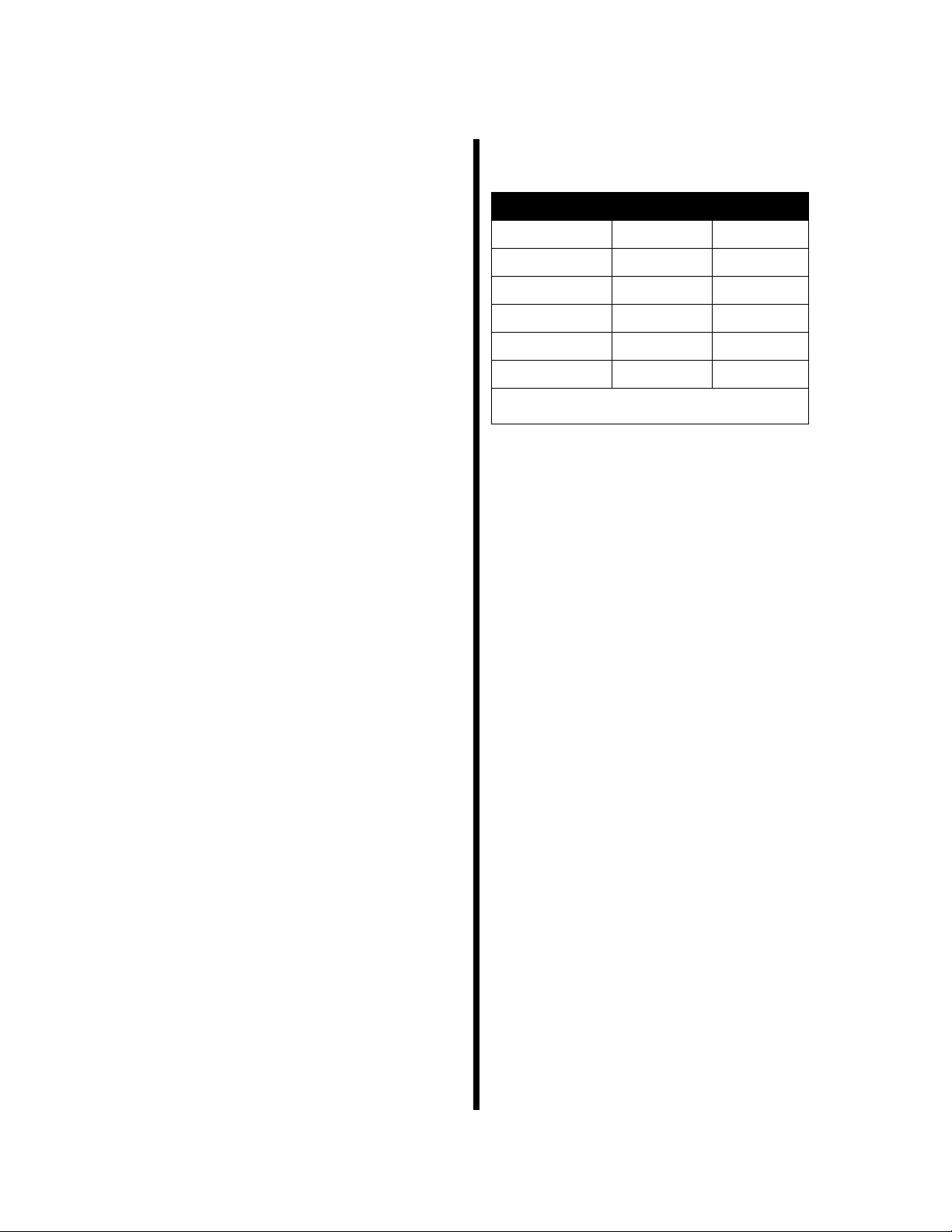
RATINGS
CONTACT RATING:
TYPE OF LOAD T120VACext 277VAC
Resistive 15A 15A
Ballast 10A 10A
LED Driver 1200W 1200W
Tungsten 960W -
Motor 1/2 HP -
Pilot Duty 360VA -
Note: No minimum load requirement.
Dual Voltage Input:
120/277 VAC (No Minimum Load)
•Maximum Load: 960Watts, 10 amps @ 120 VAC
•Maximum Load: 1200Watts, 10 amps @ 277 VAC
Environment:
•Operating Temperature: 0-100°F
•Operating Humidity: 90% RH non-condensing

10
Cooper Lighting Solutions Installation instructions
Digital Wall Switch Timer
SETTINGS
•The tamper resistant time-on interval can be preset. In addition, a manual scroll-up mode can override the setting tempo-
rarily – this feature can be disabled, thereby providing a fixed interval timer.
• A flicker of the lights and/or a beep warning begins 2 minutes before time-out (either or both can be disabled). This docu-
ment covers installation of the following products.
The TSW-MV is factory preset to meet newer energy code override mandates. No adjustment is required. This setting
will provide a two hour maximum operating time before shut off. The scroll feature is active to allow the user to change the
operating time with the maximum time setting at two hours.
Close the timer door and the unit is ready. One press of the bottom cover turns the load ON. The load will stay ON until a
count-down to the preset OFF time. Pressing the bottom cover again will turn load OFF.
SET FOR:
1. 4HR: Set ON for preset 4 hour maximum count-down when 2HR is set to OFF. (Also used in custom time programming.)
2. 2HR: Set ON for preset 2 hour maximum count-down when 4HR is set to OFF. (Also used in custom time programming.)
3. LIMIT: Used with programming sequence. Switch from ON to OFF to limit scroll to match custom time.
4. SCROLL: Set ON allowing the timer to scroll to a shorter run time. Set OFF to disable. Switch from ON to OFF to set a
custom time. (Also used in programming sequence.)
The time scrolls in steps:
• 5 minute steps from 5 minutes to 1 hour.
• 10 minute steps from 1 to 4 hours.
• 30 minute steps from 4 to 12 hours.
• 1 hour steps from 12 to 24 hours
5. BEEPER: Set ON activating the feature for a beep warning every 15 seconds starting 2 minutes before OFF.
6. BLINK: Set ON activating a feature for load flash 2 minutes before OFF.
“ “= Beeper
“ “ = Blink
RESET BUTTON
TIMER BUTTON
ON - SWITCH UP
OFF - SWITCH DOWN

Digital Wall Switch Timer
13
Cooper Lighting Solutions Installation instructions
SINGLE POLE WIRING
THREE-WAY WIRING
OPERATION
1. To turn load ON, press the START/STOP button momentarily.
• The LCD will display the count-down time interval selected. The time interval will start counting down.
TROUBLESHOOTING GUIDE
1. To test the unit, set the DIP Switch to the minimal time-out interval (5 minutes).
2. If the unit does not function:
a. Check the ground wire. Make sure the box has good ground and is attached properly.
b. Check all other wiring to make sure connection is secure.
c. Check if power is turned back on at the main circuit breaker panel.
d. If the unit still does not function, consult the factory.
3. If the load will not turn OFF automatically:
a. Check if the load goes ON/OFF when pressing START/STOP button. If not, check the red wire for good connection.
If load does go ON/OFF, consult the factory.

Cooper Lighting Solutions is a
registered trademark.
All trademarks are property
of their respective owners.
Cooper Lighting Solutions est une
marque de commerce déposée.Toutes
les autres marques de commerce sont
la propriété de leur propriétaire
respectif.
Cooper Lighting Solutions es una
marca comercial registrada.Todas las
marcas comerciales son propiedad de
sus respectivos propietarios.
Product availability, specifications,
and compliances are subject to
change without notice.
La disponibilité du produit, les
spécifications et les conformités
peuvent être modifiées sans préavis.
La disponibilidad de productos, las
especificaciones y los cumplimientos
están sujetos a cambio sin previo
aviso.
Cooper Lighting Solutions
1121 Highway 74 South
Peachtree City, GA 30269
P: 770-486-4800
www.cooperlighting.com
© 2020 Cooper Lighting Solutions
All Rights Reserved
Tous droits réservés
Todos los derechos reservados
Printed in USA
Imprimé aux États-Unis
Impreso en los EE. UU.
Publication No. IB053060EN
December 2019
Warranties and Limitation of Liability
Please refer to www.cooperlighting.com for our terms and conditions.
Garanties et limitation de responsabilité
Veuillez consulter le site www.cooperlighting.com pour obtenir les conditions générales.
Garantías y Limitación de Responsabilidad
Visite www.cooperlighting.com para conocer nuestros términos y condiciones.
Table of contents
Popular Timer manuals by other brands

Woods
Woods 50007 instruction manual

Emerson Research
Emerson Research SmartSet JMK2442 user manual

Current Solutions
Current Solutions InTENSity 5000 Hybrid Quick reference guide

Aube Technologies
Aube Technologies TI040 Installation and user guide

red lion
red lion LD user manual

REV
REV EMT450 Assembly and operating instructions