installation manual TWIN 80 EN
10
1.5. Condensing boiler
The concentric air inlet and exhaust outlet need to be
connected with one of the adapter sets.
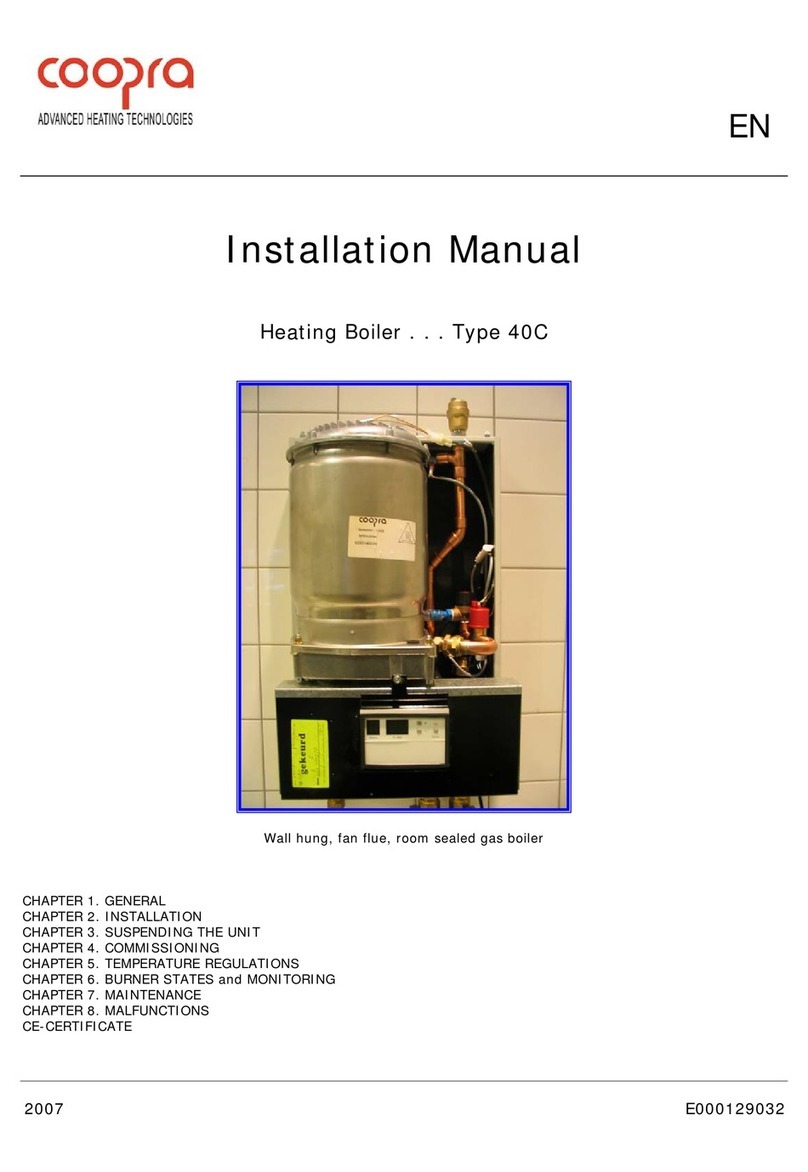
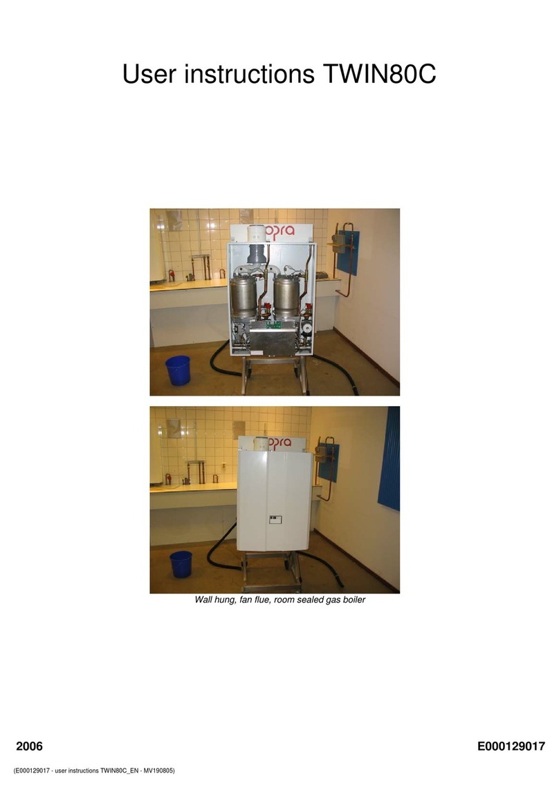
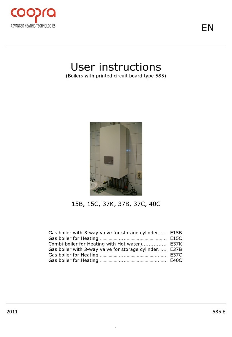
The TWIN 80C is a wall hung, fan flue, room sealed, high
efficiency condensing gas boiler for central heating and / or
under floor heating systems.
The type plate, which specifies the type of gas etc. to be used, for
which the unit is set, is on the left side of the unit.
1.6. Operation
The appliance is equipped with pre-set gas/air ratio regulators.
The purpose of this regulator is to keep the gas/air ratio in the
burner as optimal as possible at all times e.g. when modulating.
This ensures clean and reliable combustion across the entire
load range. In addition it achieves high part-load efficiency.
The TWIN 80C incorporates 2x type 40C heat units (existing of
2x heat exchanger, 2x premix burner, 2x fan, 2x gas valve, 2x
venturi, 2x circulation pump, 2x printed circuit board). Each heat
burner works independently, cascade controlled by two printed
circuit boards.
A fan sucks the air required for the combustion through the air
feed canal (A). Because the combustion air in the venturi sucks
an under pressure, the correct amount of gas (G) is
automatically added to the combustion air.
The flammable gas/air mixture thus obtained is fed to the
burner(s), via a mixing chamber, to be ignited at the surface of
the burner(s) by a ceramic glow plug. The hot combustion gases
are efficiently fed through the heat exchanger(s), where they
give their heat to the system water. The flue gases are fed
outdoor, through the flue tube (F), into a combined flue tube
exhaust canal.
The formed condensation water (H2O) is discharged through the
waste trap.
1.6.1. Display
The display operates for both printed circuit boards.
Open the door in front of the jacket for operating and reading the
codes on the display, - The boiler of this picture is in the
stand-by mode, because the display
shows a continuous 0.
- The actual water temperature of
the flow sensor is 19‘C.
1.6.2. Master – Left hand side printed circuit board.
The Master is the leading board, calculates and divides the
necessary power over both units. Therefore the regulation
controls will always be connected to the Master.
•Room thermostat 24 Volt default
•Outdoor temperature sensor default
•OpenTherm regulation default
•Room thermostat 230 Volt optional
•Direct control 0-10 Volt optional
Note: Spare part boards are set for SLAVE.
If needed, make SLAVE (A=1) into MASTER (A=0).
1.6.3. Slave –right hand side printed circuit board.
In case of a lock-out of the Master printed circuit board the Slave
is still able to operate correctly.
1.7. LED indication
Two LED’s have been placed under the appliance informing the
user the status of each unit individually.
The left hand side LED (L) is indicating the actual status of the
Left hand side heating unit.
•LED is ON = burner concerned is ON
•LED is OFF = burner concerned is OFF
•LED is FLASHING = unit concerned is LOCK-OUT
The right hand side LED (r) is indicating the actual status of the
right hand side heating unit.
•LED is ON = burner concerned is ON
•LED is OFF = burner concerned is OFF
•LED is FLASHING = unit concerned is LOCK-OUT
Concentric
100/150 mm
N00M990080
Concentric
110/150 mm
N00M990082
or
or


