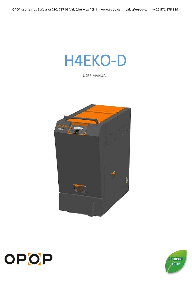
Opop H 412 User manual

Heat and Comfort
1
OPOP spol. s r.o.
Zašovská 750, 757 01 Valašské Mezi íčí
Tel.: 571 675 589, Fax: 571 611 225
CENTRAL HEATING BOILER
H 412,H 418, H 424, H 430
Content
1. Introduction 2
2 . Boiler Properties 2
3. Technical Description 3
4. Main Dimensions 5
5. Technical Parameters 10
6. List of Replaceable Spare Parts 11
7. List of Accessories Supplied 14
8. Servicing the Boiler 15
9. Boiler and Heating Equipment Maintenance 17
10. Safety Instructions for Boiler Assembly and Servicing 18
11. Waste Disposal 25
12. Determination of Storage Tank Size 26
12. Warranty Sheet 26
13. Registration Card 29
THE EUROPEAN REGIONAL DEVELOPMENT FUND AND THE
MINISTRY OF INDUSTRY AND TRADE OF THE CZECH
REPUBLIC SUPPORT INVESTMENT IN YOUR FUTURE.

Heat and Comfort
2
1. INTRO UCTION
Dear Customer,
We appreciate you have chosen a product originating from our product range, by which
you became one of our customers. We hope our product will serve you long and well.
This is contributed to by all the staff of the company and now it is up to you to make
your own contribution by reading carefully through the manuals and maintaining the
instructions and regulations specified therein.
May our products bring you heat and comfort,
OPOP s.r.o.
2. BOILER PROPERTIES
Courtesy of their design and surface treatment, the H4 series hot water steel boilers are
intended for level and central heating of detached houses with the maximum hydrostatic
height of 20 m. The boilers make it possible to combust solid fuels such as lignite and
wood.
Note: Primary combustion air supply via the stoking door must be adjusted
in order to allow combustion of wood. For this change to take place the heat insulation
(1 located on the bottom part of the stoking door must be removed and a controller
chain must be connected to the flap in the stoking door (2 . When combusting wood, the
choker stays completely in the ash pan door.

Heat and Comfort
3
Obr. – spalování uhlí – coal combustion; spalování d eva – wood
combustion
3. Technical escription
The upper part of the boiler consists of a stoking door fitted on hinges and a
cleaning door attached to the weldment by means of fly nuts. The door is sealed tightly
to the boiler body by a heat insulation rope. The actual boiler body is a welded structure
consisting of steel sheeting. Seen from above, it is divided by water partitions into three
parts:
a) the frontal space behind the front wall of the boiler forms a charging shaft with a
moving alloy grate;
b) the central part forms the combustion space complete with a chamotte shaped brick
provided in the upper part for improved combustion of flue gases;
c) the rear space forms a reverse draft, where the combustion gases flow to under the
bottom part of the last partition and subsequently ascend into the smoke bell. In the

Heat and Comfort
4
upper part of the space, there is a movable heating flap, which allows direct flue gas
removal from above to the bell.
The boiler fireplace is fitted with a movable cascade grate controlled by a lever on the
side of the boiler. The amount of secondary air supplied is manually adjustable for H4
boilers on both side shells of the boiler. Under normal operating conditions respecting
the nominal power, the flaps are fully open.
The boiler may be operated with both lignite (grain 1) and fuel wood at the maximum
length of 25cm for H412 and H418 boilers and 30cm for H424 and H430 boilers.
The ash pan door is fitted with a choker for combustion air control, coal combustion
and the stoking door is fitted with a choker for combustion air control, for wood
combustion with the use of an automatic combustion air controller. Whenever a change
in fuel occurs, adjustments must be effectuated, see the note in Page 1. In order to meet
the requirements of the ČSN EN 303-5 Standard (Central Heating Boilers Operated with
Solid Fuel with Manual or Automatic Feed, At Nominal Heat Generating Capacity of
Max. 300kW), the boiler must be operated in absence of an inserted ash pan drawer in
the ash-pan compartment; otherwise the ash-pan drawer must be emptied at increased
frequency.
The air supply and discharge flanges as well as the bell are located along the central
axis of the rear boiler part. In the upper part a 3/4" sleeve is provided for the connection
of the combustion air control and a 1/2" sleeve to place the anti-overheating safety
equipment sensor; in the lower part, there is a 1/2" sleeve provided for the discharge and
filling cock.
The walls of the boiler are heat insulted and covered by surface treated cover plates.
The stoking, cleaning and ash pan doors are made of surface treated parts and are heat
insulated. The temperature and pressure gauges are fitted in the cover plate, taking
temperature and pressure measurements of the heating water inside the boiler.

Heat and Comfort
5
4. Main imensions Table relating to Fig. 2
H 412
H 418
H 424
H 430
A – Total Boiler Height 865 865 865 1005
B – Total Boiler Depth 598 670 670 670
C – Boiler Width 386 386 490 490
D – Lo ation of the Gas Flue 635 635 635 755
E – Lo ation of the Supply Water
Sleeve
99 99 99 99
F – Lo ation of the water supply
sleeve
781 781 781 921
G – Flange Size 116 116 116 116
H – Flange S rew Spa ing 67 67 67 67
J – Boiler Base Depth 398 470 470 470
K – Boiler Base Width 316 316 420 420

Heat and Comfort
6
Fig. 1 - H412 Boilers

Heat and Comfort
7
Fig. 2: H418 Boilers

Heat and Comfort
8
Explanatory Notes:
1 – H418 Boiler Body
2 – Grating Mechanism
4 – Heat-up Flap
5 – Cleaning Stopper
9 – Grating Mechanism Lever
10 – Ash Pan Drawer
15 – Stoking Door
16 – Cleaning Door
17 – Ash Pan Door
19 – Movable Grate
20 – Inclining Grate
27 – Handle
33 – Frontal Cover
34 – Side Cover
37 – Cooling Loop
39 – Flange
41 – Automatic Combustion Air Controller
58 – M10,30 Screw
64 - M10 Nut
69 – 10.5 Washer
84 – 0-120°C Thermometer
85 – Fibrous Sealing
89 – 0-4 Bar Manometer

Heat and Comfort
9
Fig. 3: H424 Boilers

Heat and Comfort
10
5. Technical parameters for Coal table 2
H 412 H 418 H 424 H 430
Operating Flue (mbar) 0.18 0.18 0.22 0.27
Water Volume ( l ) 22.7 26 35 42
Bell Diameter (mm) 130 130 160 160
Boiler Hydrauli Loss at ∆T 20°/10° (mbar) 0,1/0,37
0,19/0,7
0,28/1,1
0,38/1,4
Boiler Class 2 2 2 2
Burning Time at Nominal Power (h) 4 4 4 4
Temperature Control Range (°C) max. 90
max. 90
max. 90
max. 90
Minimum Supply Water Temperature (°C) 65 65 65 65
Fuel Shaft Volume ( l ) 35 35 46 57
Filling Hole Size (mm) 182x308
182x308
182x412
182x412
Nominal Heat Generating Capa ity (kW) 14 19 24,5 30
Combustion Gas Temperature at
Nominal Heat Generating Capa ity
(°C) 355 353 349 345
Volume Flow of Combustion Gases at
Nominal Heat Generating Capa ity
(kg/s) 0,011 0,016 0,021 0,026
Effi ien y (%) 70 71 72 73
Operating Overpressure (bar) 2 2 2 2
Heating Surfa e (m2) 1.36 1.5 1.9 2.35
Boiler Weight (kg) 155 170 210 247
Fuel Consumption (kg/hour)
3,9 5,5 7,2 8.91
Type of Fuel and Fuel Water Content Lignite b2, H2O max. 20%
Fuel Size Grain
1
Technical Parameters for Wood table 3
Operating Flue (mbar) 0.18 0.18 0.22 0.27
Water Volume ( l ) 22.7 26 35 42
Bell Diameter (mm) 130 130 160 160
Boiler Hydrauli Loss at ∆T 20°/10° (mbar) 0,1/0,37
0,19/0,7
0,28/1,1
0,38/1,4
Boiler Class 1 1 1 1
Burning Time at Nominal Power (hour) 2 2 2 2
Temperature Control Range (°C) max. 90
max. 90
max. 90
max. 90
Minimum Supply Water Temperature (°C) 65 65 65 65
Fuel Shaft Volume ( l ) 35 35 46 57
Filling Hole Size (mm) 182x308
182x308
182x412
182x412
Nominal Heat Generating Capa ity (kW) 11 15,5 20 25
Combustion Gas Temperature at
Nominal Heat Generating Capa ity
(°C) 235 230 225 220
Volume Flow of Combustion Gases at
Nominal Heat Generating Capa ity
(g/s) 0,016 0,02 0,023 0,027
Nominal Heat Generating Capa ity/ min.
Heat Generating Capa ity
Effi ien y (%) 66,8 68,8 70,9 73
Operating Overpressure (bar) 2 2 2 2
Heating Surfa e (m2) 1.36 1.5 1.9 2.35
Boiler Weight (kg) 155 170 210 247
Fuel Consumption (kg/hour)
3,6 5 6,5 8

Heat and Comfort
11
Type of Fuel and Fuel Water Content Fuel Wood, H2O max. 20%
Fuel Size 25 m 25 m 30 m 30 m
Note
Fuel consumption directly depends on the quality and type of fuel used as well on the
operator’s keeping the internal heat exchange boiler surfaces clean.
6. List of Replaceable Spare Parts
Spare Parts List Spare Part Position in Fig.2
1) Stoking door 15
2) Cleaning door 16
3) Ash pan door 17
4) Inclined alloy grate 20
5) Movable alloy grate 19
6) Cleaning flap 5
7) Heating flap 4
8) Grating mechanism 2
9) Ash pan drawer 10
10) Front cover 33
11) Lateral left/right cover 34
12) Spatula and hook for cleaning boiler surface
13) Brush (holder +steel brush)
14) Thermometer 84
15) Pressure gauge 89
16) Automatic combustion air controller 41
17) Filling cock
18) Stoking door handle 27
19) Fibrous sealing 85

Heat and Comfort
12
Obr. Vybrané náhradní díly
Název dílu Číslo N Pro kotel
Šikmý rošt
Šikmý rošt
Posuvný rošt
Posuvný rošt
Čistící klapka
Čistící klapka
Čistící klapka
Zatápěcí klapka
H418030
H424030
H418031
H424031
H412001
H418001
H424001
H412002
H412V, H418V
H424V, H430V
H412V, H418V
H424V, H430V
H412V
H418V
H424V
H412V

Heat and Comfort
13
Obr. Vybrané náhradní díly
Název dílu Číslo N Pro kotel
Zatápěcí klapka
Roštovací
mechanismus
Roštovací
mechanismus
Podpěra roštu
Šamotová deska
Šamotová deska
Trubka sekundáru
Trubka sekundáru
H418002
H424002
H418023
H424030
H424022
H418040
H424040
H418041
H424042
H418V
H424V, H430V
H412V, H418V
H424V, H430V
H424V, H430V
H412V, H418V
H424V, H430V
H412V, H418V
H424V, H430V

Heat and Comfort
14
Part Name Spare Part No. Boiler No.
Inclining Grate H418022 H412,H418
Movable Grate H418021 H412, H418
Movable Grate H424026 H424, H430
Cleaning Flap H412001 H412
Cleaning Flap H418001 H418
Cleaning Flap H424001 H424, H430
Heat-up Flap H412002 H412
Heat-up Flap H418002 H418
Heat-up Flap H424002 H424, H430
Grating Mechanism H418023 H412, H418
Grating Mechanism H424030 H424, H430
Grate Support H424022 H424, H430
Fireclay Board H418040 H412, H418
Fireclay Board H424040 H424, H430
Secondary Tube H418041 H412, H418
Secondary Tube H424041 H424, H430
7. List of Supplied Accessories
1) Spatula and hook for cleaning boiler surfaces
2) Brush (holder +steel brush)
3) Filling cock
4) Automatic combustion air controller
5) Shielding plate (for H412 and H418 only)
6) Stoking door handle + fixing screws
7) Grating mechanism lever

Heat and Comfort
15
8) Flange (2 items)
9) Fibrous sealing (2 items)
10) M10 Screw (8 items)
11) M10 Nut (8 items)
12) 10.5 Washer (8 items)
13) Operating Manual plus warranty sheet
14) Cleaning flap
8. Operating the Boiler
Prior to initial heat-up:
Check whether the boiler or the entire heating system is filled with water or other heat
bearing medium and duly de-aired.
Check the gas flue path for tightness.
Check the fixture of the cleaning flap (no. 5) so as to prevent sucking false air into the
exchanger space.
When using lignite as fuel, attach the controller chain to the flap in the ash pan door.
The flap in the stoking door is closed. Heat insulation is provided in the lower part of
the stoking door.
When using wood as fuel, connect the controller to the stoking door flap. The flap in the
ash pan door is closed, the heat insulation of the stoking door is removed.
8.1 Heating Up
The method of heating the boiler up is the same as that for an ordinary stove. Use the
upper door to throw paper onto the grate and add firing chip and several larger sized
pieces of wood. Using a piece of lit paper, set the charge on fire from below. Close the
ash pan door and check whether the opening of the door choker using an automatic
combustion air controller works properly. In the event of low chimney draft, open the
heating flap by pushing the tie rod towards the inside of the boiler body and close the
secondary air inlets on the boiler sides. As the wood burns out, gradually add more fuel
and make sure that you do not quench the fire by adding too large quantities of fuel
prematurely. Proceed in this way until the quantity of stoked fuel exceeds the lower edge
of the first partition. Then, you will be able to add as much fuel as to fill the filling shaft
to such a height that tight closure of the door is ensured. Once the fire’s intensity has
grown, close the heating flap by pulling the tie rod on the rear boiler wall and open the
secondary air inlets on the boiler sides.

Heat and Comfort
16
In order to prevent any smoke leakage when opening the stoking door and stoking fuel,
take the following procedure:
- prior to stoking, close the air supply using the choker in the ash pan door and
slightly open the stoking door by roughly 1 to 1.5 cm in the frontal part of the
stoking door Wait for about 10 seconds until the smoke gases are sucked away and
then open the stoking door fully. After replenishing fuel, open the air supply
again. In the event of good chimney draft or if the filling shaft is full, the present
procedure does not need to be taken.
8.2 Ash Removal
In order to ensure good access of the combustion air for perfect combustion, the
remnants of burnt-out wood must be removed in time – namely the ash from the grate.
This shall be done by tilting the lever provided on the side wall of the boiler. The
movement is used to shift the grate, thereby making the ash fall through into the ash pan
space. In the event that remnants of clay are formed on the grate, remove it from the
boiler in operation by prolonging the movement of the lever. As a result, the cascade
grate will move clear and the coarse remnants of fuel will fall through into the ash pan
space. If the clay remains hanging from the grate, shake it off by shifting the lever more
rapidly.
The same procedure shall be taken when cleaning the boiler after the heating has been
completed. Make sure that remnants of ash which might potentially fall through beyond
the ash pan drawer and hinder proper insertion thereof do not accumulate in the space
for the ash pan drawer.
8.3 Cleaning the Boiler
In order to arrive at the most economical and as a result the most efficient operation
of the boiler, the internal part of the boiler body must be duly cleaned from time to time,
namely once a fortnight or a month (depending on the heating intensity and the fuel
used). That shall be done by vigorously scratching off any wall deposits by means of a
spatula or a steel brush included to the boiler as part of the accessories. The boiler shall
be out of blast when subjected to the cleaning.

Heat and Comfort
17
Follow the below cleaning procedure:
a) Slip the ash pan drawer to the ash pan compartment;
b) Remove the cleaning door (16) and the heating flap (4). Use the hook
provided to remove the cleaning flap (5) located in the rear boiler part on the
bottom of the rear venting hole. The cleaning flap closes the space between
the rear partition venting hole and the ash pan drawer. Use vigour to scratch
down any deposits along the boiler walls using the spatula and the steel brush
provided. In order to remove impurities, fix back the cleaning flap and, using a
portable lamp, check whether the flap is properly fitted;
c) Use the above reversely to return the heating flap back to the boiler, close the
cleaning door and adequately finish tighten the two fly nuts in the rear part of
the cleaning door;
d) Perform the same cleaning procedure for the frontal part of the boiler in the
charging shaft while leaving the stoking door open;
e) Remove remnants of clay and ash from the grates by acting on the grating
lever;
f) Remove the ash pan drawer via the open ash pan door, empty the content of
the ash pan drawer, clean the ash pan drawer compartment of any remaining
clay and ash that may have fallen beyond the ash pan drawer during the
cleaning procedure and close the ash pan door.
CAUTION!!! The ash must be deposited in a non flammable flapped
vessel.
9. Boiler and Heating Equipment Maintenance
Before commissioning the heating facility, fill the water system of the heating
equipment with water—soft water if possible. Check the state of the water in the heating
equipment from time to time. Never heat the boiler to beyond 90oC. Mild bubbling in
the boiler body at temperatures above 80oC is not detrimental. It is however,
detrimental, if the equipment responds to lower temperatures by any surges, etc. That
usually indicates an improper assembly or air-filled system of system that has not been

Heat and Comfort
18
replenished with water. If needed, the water system may be filled with non-freezing
liquid, Friterm (www.velvana.cz), or a non-corroding product, Inhikor II.
The user shall trust the commissioning, regular servicing and removal of any defects to a
specialised service only.
10. Safety Instructions for Boiler Assembly and Servicing
A solid fuel boiler may only be installed by a company holding a valid certificate
authorising it to install the equipment or any a person authorised by our company (see
the list of servicing companies). A project must be drafted for the installation subject to
the applicable regulations. For reference please see the fundamental conditions applying
to the assembly included in this document.
Prior to commissioning the boiler, make it complete (elements that must be installed as
late as after transport are stored in the ash pan as boiler accessories).
10.1 Draft Controller Assembly and Setting
In the upper part of the boiler an on-welded ¾” catchment is provided for the
installation of the boiler draft controller. The bushing provided for the draft controller
must be screwed (packed) into the catchment in a waterproof fashion, and the instrument
must be set by following the assembly instructions provided by the manufacturer of the
controller.
CAUTION!!! The minimum spacing of 200 mm between the head of
the controller and the smoke-flue must be respected. If the head is spaced
less than that, the smoke-fuel must be heat insulated with regard to the
head; otherwise the plastic head bushing might melt down.
10.2 Discharge Valve Assembly
In the rear part of the boiler, an on-welded ½” sleeve is provided, into which the
discharge valve must be screwed (packed). After filling the system with water, the valve
must be closed!
10.3 Connection to the Chimney
Recommended chimney diameters for central heating boilers – the data are
given for reference only.

Heat and Comfort
19
Boiler Capacity
kW
Chimney Height 8m
Chimney Height 12m
Chimney Height 15m
12 15 x 15
18 15 x 20
24
Ø
180 mm
30 Ø 180 mm
35 Ø 200 mm
49,5
Ø
200 mm
Chimney Diameter in mm
The boiler may only be installed to the chimney to ČSN 73 4201:1989 (Design of
Chimneys and Smoke Flues).
Connection of the hot water boiler must not be performed unless approval has been
granted by the chimney organisation.
The boiler must be connected to a separate venting unit of sufficient draft for all
practically possible operating conditions.
A piping circuit fixed in the chimney flue and fitted on the smoke bell of the fuel
consumer must be fixed and slipped on in order to prevent it from getting accidentally or
spontaneously released.
The individual smoke flue pipes must be inserted into one another along the length of at
least 80 mm. It is recommended that the smoke flue leading from the boiler to the
chimney be up to 1m long and that it run up towards the chimney (approx. at 1:20).
The hot water system must be executed to ČSN 06 0310:1983 (Central Heating, Design
and Assembly), ČSN 06 0830:1996 (Security Equipment for Central Heating and Utility
Water Heating).
The boiler and the smoke flue must comply with ČSN 06 1008:1997 Fire Regulations
(Fire Safety of Heat Generating Equipment), ČSN 73 0823:1984 (Fire Engineering
Properties of Materials. Flammability Classes of Materials) and may be installed at a
safe distance of 200 mm from flammable materials of classes B, C1 and C2. The above
safe distance of 200 mm must be doubled if the appliances and smoke flues are located
in the vicinity of flammable materials of the flammability class C3. The safe distance
must further be doubled if the flammability class of a flammable material cannot be
identified.
The safe distance may be reduced to half in the event that a non-flammable heat
insulation shielding plate of class A is used, at the minimum thickness of 5mm, located
25cm from the shielded flammable material (air insulation) .
10.4 ivision of Materials into Flammability Classes (see ČSN 73 0823:1984).

Heat and Comfort
20
A) non-flammable
B) hardly flammable
C1) flammable with difficulty
C2) medium flammable
C3) easily flammable
A) non-flammable: stone, granite, sand stone, concrete mixes, porous
concrete, foam concrete, bricks, fireclay, mortars,
plastering, metals, glass and other mineral melts, asbestos-
cement plates
B) hardly flammable: Acumine, Izomine, plasterboard plates, Heraclites,
Lignos, Rayolite, Velox, novodur, Durufol B, Duroplast
H, Dekorplast, Rotizol, basalt felt, Haver, glass-fibre mat
C1) flammable with difficulty: hard timber, beech, oak, plywood, Hobrex,
Sirkolite, Werzalite, Ecrona, Umakart
C2) medium flammable: white-sawn timber, pine, larch, spruce, chipboard plates,
Piloplat, Duplex, Solodur, cork plates SP, cork parquet
C3) easily flammable: laminated chipboard plates, sawdust boards, Pilolamite,
fibreboard, hardboard, Sololak, Sololite, BA cork boards,
Polystyrene, Polyurethane
The boiler must be operated to ČSN 33 20 00 - 3:1995 in the basic AA5/AB5
environment provided that the appliance is put out of operation in a timely fashion to
prevent the risk of fire when conditions potentially leading to temporary emergence of
flammable gases or vapours occur and while pursuing work that might involve
temporary fire or explosion hazards (such as when gluing lino, PVC, etc.).
If the flooring is made of flammable material, the boiler must be positioned on a non-
flammable heat insulating mat exceeding the boiler by at least 30 cm on the side of the
stoking and ash pan door and by at least 10 cm on the other sides.
10.5 INSTRUCTIONS APPLYING TO ASSEMBLY AN USE OF
PRESSURE EXPANSION VESSELS FOR STEEL BOILERS
1) The supply line leading up to the pressure expansion vessel must be as short as
possible, free of closures and with space provided for any dilatation. The
This manual suits for next models
3
Table of contents
Other Opop Boiler manuals
Popular Boiler manuals by other brands

Gorenje
Gorenje OTG80SLSIM Instructions for use

Climit
Climit 24 OF Installation and servicing instruction

Immergas
Immergas VICTRIX 24 TT 1E Instruction and warning book

Indol
Indol W381A+ user manual

Sime
Sime MURELLE PRO HE MkII User, installation and servicing instructions

Instanta
Instanta DB2000 Installation and user instructions

Burco
Burco 76700 user manual

Main
Main Combi 24 HE User's guide and important warranty information

NTI
NTI Trinity Tft399 Installation and operation manual

Timberk
Timberk SWH FSM1 30 V instruction manual

Froling
Froling Lambdatronic P 3200 operating instructions

Potterton
Potterton Housewarmer 45 Installation & service instructions