CorLiving FPE-206-F User manual

1
IMPORTANT:
NOTE:DO NOT RETURN UNIT TO THE STORE
BEFORE CONTACTING OUR CUSTOMER SERVICE
DEPARTMENT. DONOTDISPOSEOFYOUR
CARTONSUNTILYOUARECOMPLETELYSATISFIED
WITHYOURNEWFIREPLACEHEATER.
PLEASENOTE:WHENYOUOPENTHECARTONCAREFULLYCHECK
THEUNITANDMAKESURETHEREISNODAMAGE. IFYOUHAVE
ANYPROBLEMSWITHASSEMBLINGTHEUNIT,WITHHOWTHE
VARIOUSFUNCTIONSWORKORWITHDAMAGEORMISSINGPARTS,
PLEASEGOTOOURWEBSITE:
www.CorLiving.com/parts
NOTE:Light bulbs maybecome loose during shipping. If the flame effect is dim ordoes not
work, please check that light bulb or bulbs are fingertight in socket. See instructions for
replacing bulb orbulbs.
NOTE:The electricfireplace heater mayemit a slight harmless odorwhen first turned on.
This is caused byactivating the internal heatercomponents forthe first time and should
not occuragain.
INSTRUCTIONMANUAL
ATTENTION:
1. Find a location for the fireplace heater that is protected from direct sunlight.
2. Do not plug the unit into the power outlet before reading all instructions.
IMPORTANT SAFETY
INSTRUCTIONS
WHEN USINGELECTRICAL APPLIANCES,BASICPRECAUTIONS SHOULD ALWAYS BE FOLLOWED
TO REDUCE THE RISKOF FIRE,ELECTRICSHOCK,AND INJURYTO PERSONS,INCLUDING THE
FOLLOWING:
1) Read all instructions beforeusing thiselectric fireplaceheater.
2) This electric fireplace heateris hot when in use.Toavoid burns,donotletbareskin
touch hotsurfaces. The grill directlyin frontof theheateroutletbecomeshotduring
heater operation. Keep combustible materials,such asfurniture,pillows, bedding,
papers, clothes, and curtainsatleast 3 ft(0.9m)awayfrom thefrontof the unitand
keep them away from the sides and rear.
3) Extreme caution is necessary when anyheaterisused byornearchildren
or individuals with disabilitiesand wheneverthefireplaceisleftoperatingand
unattended.
4) Always unplug fireplace when not in use.
5) Do not operateany electric fireplace with a damaged cord orplug or after the heater
malfunctions, has been dropped or damaged in anymanner.
6) Do not use outdoors.
7) Thiselectric fireplaceheater isnot intended foruse in bathrooms, laundryareas and
similar indoor locations. Never locate heater where itmay fallinto a bathtub or other
water container.
8) Do not run cord undercarpeting. Do not cover cord with throwrugs, runners,orsimilar
coverings. Arrangecord away from traffic area and whereit willnot be tripped over.
9) To disconnectfireplace, turn controlsto off,then removeplug from outlet.
10) Connect to properly grounded outlets only.
11) Do not insert or allow foreign objectsto enter anyventilation orexhaust openingasthis
maycause an electric shock or fire, or damagetheheater.
12) Toprevent a possiblefire, do notblock air intakesor exhaustin any manner. Do not use
on soft surfaces, like a bed, whereopenings maybecomeblocked.
13) A heater hashot and arcingor sparkingparts inside.Do not useitin areas where
gasoline, paint,orflammable liquids are used orstored.
14) Use this fireplaceheater onlyas described in thismanual.Anyother use not
recommended bythe manufacturer may causefire,electric shock, or injury topersons.
15) Avoid the use of an extension cord becausetheextension cord may overheat and cause
a risk of fire. However, if you have touse an extension cord, thecord shall be No.14 AWG
minimum size and rated notless than 1875 watts.
16) Do not plug thisproduct into a receptaclecontrolled bya wallswitch or dimmer.
17) When storing or transporting theunitand cord, keep in a dryplace, free from excessive
vibration and store so as toavoid damage.
SAVE THESE INSTRUCTIONS FOR
FUTURE USE.
CAUTION:
If you use this heater in conjunction with a thermal control, a program controller, a timeror
any otherdevice that switches the heater on automatically, remember to observe all safety
warnings at all times. The fireplace heater has safetyoverheat protection. If the overheat
protection trips, switch off all switches and wait approximately 5– 10 minutes. It should
reset automatically once the unit cools down.
WARNING:PROCEDURESANDTECHNIQUES,IFNOTCAREFULLYFOLLOWED,WILLRESULTIN
DAMAGETOTHEEQUIPMENT,ANDWILLEXPOSETHEUSERTO THERISKOFSERIOUSINJURY,
ILLNESSORDEATH.
PO#
32” Wall Mount Fireplace
Model : FPE-206-F
This electric fireplace heater is for use on 120 volts. The cord has a plug, as shown at A
in illustration below. An adapter, as shown at C, is available forconnecting three-blade
grounding-type plugs to two-slot receptacles. The green grounding plug extending from the
adapter must be connected to a permanent ground such as a properlygrounded outlet box.
The adaptershould not be used if a three-slot grounded receptacle is available.
A15amp circuitisrequiredtooperatethisheater. Ifthebreaker trips whentheheaterisused,
youmayneedtomovethe heatertoanotherlocationorunplugotherappliancesthatareon the
samecircuit.Ifyourequireanextension cord,useone thatisratedat1875watts.

2
Step
nuoM
Remove the front cover by pulling it upward until the front cover has
been removed from the 4 locking posts located on both sides. See Fig. G.
:4
t the fireplace to the mounting bracket. The extruded flange on the back of
fireplace should be fully inserted into the mounting bracket. See Fig. F.
Fig. G
ASSEMBLY INSTRUCTIONS
PARTS LIST
Fireplace ...............................................................................................................................1
A) Mounting bracket.......................................................................................................... 1
B) Mounting Screws for wall anchors .............................................................................3
C) Wall Anchors.................................................................................................................. 3
D) Washers
E) Plastic Pads......................................................................................................................
..........................................................................................................................3
3
F) Screws for wood studs ................................................................................................... 2
TOOLS REQUIRED: Level, electric drill, drill bits 5 /16 in (8 mm), Phillips screw-
driver, hammer, safety goggles and gloves.
CAUTION: The Fireplace Mantel should not be positioned in an area exposed to
direct sunlight.
A
B
E
F
C
D
Step 3: Secure the MOUNTING BRACKET (A) to the wall useing the 2 supplied
SCREWS (F) and WASHERS (D). See Fig. B
Continue to “Step 4”.
fig. B
fig. A
Step 1: Select the wall location where you want to hang your electric fireplace.
Measure the area where the mounting bracket will be installed. Using the level, draw
a guide line. Mark on the line where you will drill your holes for the mounting screws.
Use the guide line as the center line to ensure your fireplace will be mounted staight
and level. See Fig. A
INSTALLATION - Wood stud wall
Note: When mounting to wooden studs, 2 studs 16” on center must be used to affix Wall
Plate (A) to wall to ensure enough support. Use of a “Stud Finder” is recomended.
WARNING: This mount is only intended for use with standard 16” on center wood stud
spacing. It will NOT work for stud spacing longer than 16” on center.
Step 2: Drill 2 holes on the marked locations [1/8” (3mm).
fig. D
fig. C
fig. E
Step 1: Select the wall location where you want to hang your electric fireplace.
Measure the area where the mounting bracket will be installed. Using the level, draw
a guide line. Mark on the line where you will drill your holes for the mounting screws.
Use the guide line as the center line to ensure your fireplace will be mounted staight
and level. See Fig. C
INSTALLATION - Concrete wall
Step 2: Drill 3 holes on the marked locations [5/16” (8 mm).
Concrete mounting: use the supplied WALL
ANCHORS (C). Install the WALL ANCHORS
into the holes and gently tap place with a
hammer, until the flange of the wall anchor
is flush with the wall surface. See Fig. D
Step 3: Secure the MOUNTING BRACKET (A) to the wall useing the 3 supplied
SCREWS (B) and WASHERS (D). See Fig. E
Fig. F
Re-Install the front cover by lowering on to 4 locking posts
Fig. G

3
OPERATION
After reading complete instructions, confirm all controls on fireplace are in the OFF position.
Plug the fireplace into a 15AMP/120Volt outlet.
OPERATION BYTHECONTROL PANEL
The main ON/OFF switch is located at the top of yourfireplace.
TOP
O/I: Press this button for main power. The indicatorlight will turn on. The fireplace is
now ready to operate by the remote control handset.
OPERATION BYTHEREMOTE CONTROL
The fireplace is ready to operate with the remote control when the
O/I switch is in the ON position.
:Standby switch. Press this switch once and it will beep.
The unit becomes energized and you can select the
following functions, as desired. Press this button again,
the unit will be off and enter the standby mode.
The fireplace is preset to start with high heat (1500W) and the
highest flame intensity.
:Press this button once for flame effect. The unit will beep.
Press again to increase the flame intensity. There are 6
light intensities for your selection. The flame optics will go
higher under the sequence of OFF, 1, 2, 3, 4, 5 and 6.
750W 1500W
750W: Press this button for low heat level. The unit will beap. The fireplace heater will
give low heat level. Press once again will stop the low heat level function.
1500W: Press this button for high heat level. The unit will beep. The fireplace heater will
give high heat level. Press once again will stop the high heat level function.
Note: When the O/I switch is turned off, all other heater functions will stop even though
the switches may be in the on position.
REMOTE CONTROL BATTERY REPLACEMENT
Replace with a CR2025 battery and follow the diagram at the back of remote handset to
install the new battery.
MAINTENANCE
WARNING: DISCONNECTPOWERANDUNPLUGTHEPOWERCORDBEFOREATTEMPTINGANY
MAINTENANCEORCLEANINGTOREDUCETHERISKOFFIRE,ELECTRICSHOCKORDAMAGE
TOPERSONS. THEBULBSINYOURUNITCAN BECOMEEXTREMELYHOT.ALLOWATLEAST10
MINUTESBETWEEN TURNINGOFFTHEUNITANDREMOVINGTHELIGHTBULBSTO AVOIDTHE
ACCIDENTALBURNINGOFTHESKIN.
RISKOFFIRE: DONOTEXCEEDTHERECOMMENDEDBULBWATTAGE.
REPLACINGTHE LIGHT BULBS
Step 1:Remove the front coverby pulling it upward until the front cover has been removed
from the 4locking posts located on both sides. See Fig. G.
Fig. G
Step 2:Then remove the rock bed from the fireplace. See Fig. H.
Fig. H
Step 3:Remove the lower cover byloosening 11 screws as shown in Fig. I. You will find 2 x
40 watt type B-10bulbs.
Fig. I

4
Step 4: Loosen and remove burnout bulb(s) and replace with newbulb(s).
Step 5: Replace the lower cover and re-attach the 11screws.
Step 6: Replace the rock bed.
Step 7:Hold the front covertightlyand engage it with the 4locking posts on both sides of
the fireplace. Make sure the front coverhas been completelyput into ALL 4 locking
posts before releasing yourhands.
Step 8: Plug in the unit.
CLEANING
To clean the unit, first turn off the controls on the unit and unplug the unit from power
source. To clean the glass display panel, remove dust with clean dry cloth. Remove finger
prints and other marks clean glass with clean damp cloth. Do not use abrasive cleaners
or spray liquids on glass display panel surface. Metal and metal painted parts should
be cleaned with a damp cloth. Do not use abrasive cleaners or spray liquids on these
surfaces.
WARRANTY
Made in China
LIMITED 1-YEAR WARRANTY
1) The warranty is a consumer warranty and applies only
to products manufactured by CorBrands Distributing,
LLC under the name brand CorLiving™. Products
must have been purchased from an authorized
CorLiving™ Distributor or Dealer, recognized by
CorBrands Distributing, LLC.
2) The warranty period is from the verified purchased
date of the product. The warranty is expressly limited
to the replacement of components having
manufacturer defects only and on current available
models.
No assembly labor is included. Possible replacement
of components or parts does not extend this limited
warranty or begin a new warranty period.
3) CorBrands Distributing, LLC products are warranted to
the original purchaser and are not transferable.
The warranty is limited to defects in manufacturing,
materials, and workmanship. This warranty does not
apply to normal wear and tear. If the product has been
subject to abuse, misuse, improper care or use of the
product, the warranty is void.
4) The consumer has purchased this as a
Ready-To-Assemble product, which involves
“Do-It-Yourself”, assembly, including: handling,
transporting, assembling and erecting the product.
CorBrands Distributing, LLC shall not be liable for
incidental or consequential damages, which results
through the use of CorLiving™ products.
5) This warranty includes any statutory legislation in the
jurisdiction where the product is purchased and does
not exclude or limit your legal right.
6) Warranty service is available by contacting CorLiving™.
Warranty period to be verified by date of
manufacturing and original/receipt of sale.
DO NOT RETURN IT TO THE STORE!
CALL US FIRST!
1.800.424.6710
MISSING HARDWARE?
For fast and accurate parts requests for all
replacement missing or defective parts, please visit:
www.CorLiving.com/parts
*Proof of payment is necessary for all warranty
requests. If you have any questions please call
our toll free line 1.800.424.6710

5
IMPORTANT :
REMARQUE:NEPASRETOURNERL’UNITÉAU
MAGASINAVANTDECONTACTERNOTRESERVICEÀ
LACLIENTÈLE.NEJETEZPASL’EMBALLAGEJUSQU’À
CEQUEVOUSSOYEZENTIÈREMENTSATISFAITDE
VOTRENOUVEAUFOYERÉLECTRIQUE.
VEUILLEZNOTER:LORSQUEVOUSOUVREZL’EMBALLAGE,
VÉRIFIEZSOIGNEUSEMENTL’APPAREILETASSUREZ-VOUSQU’IL
N’YAAUCUNDOMMAGE. SIVOUSÉPROUVEZTOUTPROBLÈME
RELATIFÀL’ASSEMBLAGEDEL’APPAREILOUAVECLAFAÇON
DONTLESDIFFÉRENTESFONCTIONSFONCTIONNENTOUSIVOUS
CONSTATEZDESDOMMAGESOUDESPIÈCESMANQUANTES,
ALLEZSURNOTRESITEWEB:
REMARQUE : Les ampoules peuvent s’être dévissées pendant le transport. Si
l’effet de flamme est faible ou qu’il ne fonctionne pas, veuillez vérifier si l’ (les)
ampoule (s) est (sont) bien vissée (s) dans le culot. Consulter les directives pour le
remplacement de (s) ampoule (s).
REMARQUE : Il est possible que le foyer électrique émette une légère odeur,
inoffensive, lorsque vous l’allumerez pour la première fois. Elle est causée par
l’activation initiale des composants internes de l’appareil; elle ne devrait plus être
émise par la suite.
MANUEL D’INSTRUCTIONS
ATTENTION :
1. Choisissez pour votre foyer électrique un emplacement protégé contre
l’ensoleillement direct.
2. Ne branchez pas le foyer électrique dans la prise de courant avant d’avoirlu
toutes les instructions du manuel.
DIRECTIVES DE SÉCURITÉ
IMPORTANTES
POUR UTILISER UN APPAREIL ÉLECTRIQUE, IL FAUT TOUJOURS OBSERVER DES
PRÉCAUTIONS DE BASE, AFIN DE RÉDUIRE LES RISQUES D’INCENDIE, DE DÉCHARGES
ÉLECTRIQUES ET DE BLESSURES CORPORELLES, DONT LES SUIVANTES :
1) Lisez toutesles directives avantd’utiliserle foyerélectrique.
2) Lefoyerélectrique est chaud lorsqu’ilfonctionne.Pouréviterdesbrûlures,la peau nuene
doitpas entreren contactavec lessurfaceschaudesdel’appareil.La grille,placéedevant
la sortiedu foyerdevientchaudeégalementdurantlefonctionnementdel’appareil.
Gardeztoutesmatièrescombustiblestellesquemeubles,oreillers,literies,papiers,
vêtementsetrideauxà unedistanced’aumoins0,9 m (3 pi)dudevantdel’appareil,et
gardez-lesaussià distancedes côtésetdel’arrière.
3) Faitespreuvede la plusgrandeprudencelorsqu’un foyerestutiliséà proximitéd’enfants
ou depersonnes invalides,ouparceux-ci,etchaquefoisquel’appareilestlaissé en état
demarche,sanssurveillance.
4) Débranchez toujourslefoyerlorsqu’il nesertpas.
5) N’utilisezpasun foyerélectriquedontla ficheoulecordon d’alimentation est
endommagé,ouaprès l’apparition d’un défautdefonctionnement,ouaprèsqu’ilaitété
échappéau solouendommagéd’unemanièrequelconque.
6) N’utilisezpascetappareilà l’extérieur.
7) Lefoyerélectrique n’estpasconçupourêtreutilisédansunesalledebain,unesallede
lavageouun autreemplacementintérieur semblable.N’installezjamaislefoyer là oùil
risquerait detomberdansunebaignoireouun autrecontenantd’eau.
8) N’acheminezpas lecordon d’alimentation de l’appareilsousdestapisoumoquettes.Ne
recouvrez paslecordon d’unecarpette,d’un tapisd’escaliernid’un autrerevêtementde
solsemblable.Disposezlecordon à distance desairesdecirculation etdetoutendroitoù
ilrisqueraitde faire trébucher quelqu’un.
9) Pourdébrancherlefoyer,mettez d’abord les commandesen position horscircuit (OFF),
puistirez surla ficheducordon pourl’extrairedela prisemurale.
10) Branchezl’appareiluniquementàune prisedecourantmiseàlaterredefaçonappropriée.
11) N’insérez pas d’objets dansles ouverturesd’aération oud’évacuation del’appareil,nine
laissezd‘objetsypénétrer,cequirisqueraitdeprovoquerunedéchargeélectriqueouun
incendie, oud’endommagerl’appareil!
12) Pouréviter lesrisquesd’incendie, nebloquezen aucunefaçon lesprisesd’airdel’appareil
ou sessortiesd’évacuation.N’utilisezpasl’appareilsurunesurfacesouple,commeun lit,
où sesouverturesrisqueraientde devenirobstruées.
13) L’intérieurd’un foyercontientdes pièceschaudesouquipeuventproduire desarcs
électriquesou des étincelles.N’utilisezpascetappareilen un endroitoùl’on utiliseou
entreposede la peinture,de l’essenceouautresliquidesinflammables.
14) Utilisez lefoyer électriqueconformémentauxinstructionsdumanuel.Toute autre
utilisation quin’estpasrecommandéeparlefabricantestsusceptibledecauserun
incendie, une déchargeélectrique oudes blessurescorporelles.
15) Évitezd’utiliser un câblede rallonge: ilpourraitsurchaufferetcauser un incendie.
Toutefois,sivousdevez utiliserun câble derallonge,ildoitêtred’un calibreminimal AWG
Nº14, et sa puissance nominale,d’aumoins1875W.
16) Nepasbrancher ceproduitdans une prisecontrôléepasun interrupteur muraleouun
gradateurmurale.
17) Lorsquevousrangezoutransportezl’appareiletson cordon d’alimentation,gardez-les
en un lieusec,exemptdetoutevibration excessive,pouréviterdelesendommager.
CONSERVEZ LES PRÉSENTES
DIRECTIVES POUR TOUTE
UTILISATION FUTURE.
PO#
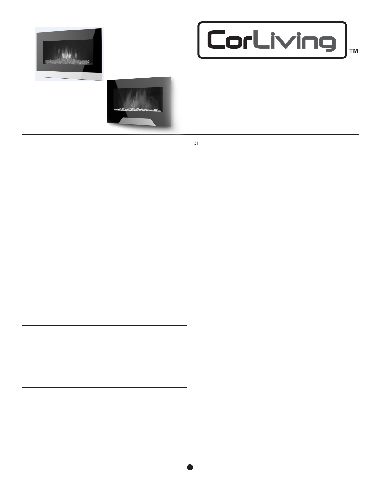
FOYER MURAL ÉLECTRIQUE
Model : FPE-205-F
www.CorLiving.com/parts
MISE EN GARDE :
Si vous utilisez ce foyer conjointement avec une commande thermique, un régulateur
à programme, une minuterie ou quelque autre dispositif qui met l’appareil en circuit
(ON) automatiquement, n’oubliez pas de respecter tous les avertissements relatifs
à la sécurité, en tout temps. Ce foyer comporte une protection incorporée contre
les surchauffes. Si la protection contre la surchauffe se déclenche, éteignez tous
les interrupteurs et attendez environ 5 à 10 minutes. Elle devrait se réenclencher
automatiquement après le refroidissement de l’unité.

6
AVERTISSEMENT : SI VOUSNERESPECTEZPASBIENPROCÉDURESET TECHNIQUES
D’UTILISATION, L’APPAREILSERAENDOMMAGÉ, ETL’UTILISATEURS’EXPOSEÀ DESRISQUES
DEBLESSUREGRAVE,DEMALADIE,VOIREDEDÉCÈS!
Ce foyer électrique est conçu pour fonctionner sur un circuit de 120 V. Le cordon
d’alimentation comporte une fiche, montrée dans l’illustration A ci-dessous. Un
adaptateur, tel que montré en C, est disponible, pour permettre de brancher une
fiche à mise à la terre à trois broches dans une prise de courant à deux broches.
La fiche de mise à la terre verte qui prolonge l’adaptateur doit être connectée
à un conducteur de terre du type permanent, comme par ex. une boîte à prises
correctement mise à la terre. Si une prise de courant à trois broches de mise à la
terre effective est disponible, n’utilisez pas d’adaptateur.
Un circuit de 15 ampères est requis pour utiliser ce foyer. Si le disjoncteur déclenche
lorsque vous utilisez l’appareil, il vous faudra peut-être le déplacer, ou débrancher
d’autres appareils partageant le même circuit. Si vous devez utiliser un câble de
rallonge, il doit avoir une puissance nominale de 1875 W.
DIRECTIVES D’ASSEMBLAGE
LISTE DES PIÈCES
Foyer...................................................................................................................
..............................................................................................
...........................................................................................
...........................................................................................
....................................................................................................
..................................................................................
.............................................................................
1
A) Support mu ral 1
B) Vis d’assemblage 3
C) Ancrages muraux 3
D) RONDELLE 3
E) Garniture en plastique 3
Outils nécessaires: Niveau, perceuse électrique, mèche 5 /16’’ (8mm), tournevis à
pointe cruciforme (Phillips), marteau, lunettes protectrices et gants de travail.
ATTENTION :
Le
foyer électrique
ne doit pas être placé dans un endroit exposé aux
rayons directs du soleil.
A
B
E
F
C
D
F) Vis pour poteaux de bois 2
INSTALLATION - Mur à ossature bois
INSTALLATION - Mur en béton
Étape 1: Déterminez l’emplacement du mur où vous voulez installer votre foyer élec -
trique. Mesurez l’emplacement du support mu ral. En utilisant un niveau, tracez une
ligne pour vous guider. Sur la ligne, tracez des points de repère aux emplacements
déterminés pour percer les trous pour les vis d’assemblage. Utilisez votre ligne de
guidage comme point central afin de vous assurer que votre foyer soit installé en ligne
droite et de niveau. Voir la fig. A.
fig. A
Remarque: Lors du montage de goujons en bois, 2 clous de 16 "sur le centre doit être utilisé
pour fixer la plaque murale (A) au mur pour assurer un soutien suffisant. Utilisation d'un
"Stud Finder" est recommandé.
AVERTISSEMENT: Ce support est conçu uniquement pour une utilisation avec 16 "standard
sur l'espacement des poteaux de bois de centre. Il ne fonctionnera pas pour l'espacement
des montants de plus de 16 "sur le centre.
Étape 2: Percez deux trous sur les emplacements marqués [1/8 "(3mm).
Étape 3: Fixez le support de montage (A) à la paroi useing les 2 vis fournies (F) et les
rondelles (D). Voir Fig. B. Continuer à "Etape 4".
fig. B
Étape 1: Sélectionnez l'emplacement du mur où vous voulez accrocher votre
cheminée électrique Mesurez la zone où le support de montage sera installée.?. En
utilisant le niveau, tracer une ligne de guidage. Marque sur la ligne où vous pourrez
percer vos trous pour les vis de montage. Utilisez la ligne de guidage de la ligne
centrale pour assurer votre foyer sera monté staight et niveau. Voir Fig. C
fig. C
fig. D
Étape 2: Percer trois trous sur les emplacements marqués [5/16 "(8 mm).
Montage de béton: utiliser les chevilles
fournies (C). Installez les chevilles dans les
trous et tapoter dessus avec un marteau,
jusqu'à ce que la bride de l'ancrage de la
paroi est de niveau avec la surface du mur.
Voir Fig. D
fig. E
Étape 3: Fixez le support de montage (A) à la paroi useing les 3 vis fournies (B)
et les rondelles (D). Voir Fig. E

7
FONCTIONNEMENTAVEC LEPANNEAU
DECOMMANDE
L’interrupteur marche-arrêt principal se trouve au-dessus de votre foyer.
SUPÉRIEUR
O/I: Appuyer sur cet interrupteur pour l’alimentation principale. Le témoin lumineux
s’allumera. Le foyerest maintenant prêt à fonctionneravecla télécommande.
FONCTIONNEMENTAVEC LACOMMANDE À DISTANCE
Le foyer peut être mis en marche avec la commande à distance
lorsque l’interrupteur de marche-arrêt (« O/I ») est réglé sur la
position de marche.
:Interrupteur du mode veille : Appuyer sur cet interrupteur
une fois. Un signal sonore se fait entendre. L’appareil
est mis sous tension, et il est maintenant possible de
sélectionner une des fonctions suivantes. Appuyer de
nouveau sur l’interrupteur pour arrêter l’appareil et passer
en mode veille.
Le foyer se met en marche au niveau de chaleur élevé (1 500 W) et
au niveau d’intensité de la flamme le plus élevé.
:Appuyer sur ce bouton une fois pour obtenir l’effet de
flamme. Un signal sonore se fait entendre. Appuyer une
fois de plus pour augmenter l’intensité de la flamme. Il y a
six (6) niveaux d’intensité. L’intensité de la flamme ira en
augmentant : OFF, 1, 2, 3, 4, 5 et 6.
750W 1500W
750W: Appuyer sur cet interrupteur pour une intensité minimale de chaleur. L’appareil
émettra un signal sonore. Le foyer dégagera une intensité minimale de chaleur.
Appuyer de nouveau sur l’interrupteur pour éteindre la fonction d’intensité
minimale de chaleur.
1500W: Appuyer sur cet interrupteur pour une intensité élevée de chaleur. L’appareil
émettra un signal sonore. Le foyer dégagera une intensité maximale de chaleur.
Appuyer de nouveau sur l’interrupteur pour éteindre la fonction d’intensité
maximale de chaleur.
Remarque : Lorsque l’interrupteur marche-arrêt (« 0/I ») est réglé sur la position d’arrêt,
toutes les autres fonctions de chauffage s’arrêtent même si les interrupteurs sont réglés
sur la position de marche.
REMPLACEMENTDES PILES DELA COMMANDE À DISTANCE
Remplacer par une pile CR2025 et suivre le schéma au dos de la commande à distance
pour l’insérer correctement.
ENTRETIEN
AVERTISSEMENT: METTREL’UNITÉHORSTENSIONET DÉBRANCHERLECORDON
D’ALIMENTATIONAVANTD’EFFECTUERTOUTEOPÉRATIOND’ENTRETIENOUDENETTOYAGE
POURRÉDUIRELERISQUED’INCENDIE,DEDÉCHARGEÉLECTRIQUEOUDEBLESSURE.
LESAMPOULESDEL’UNITÉPEUVENTDEVENIREXTRÊMEMENTCHAUDES.APRÈSAVOIR
DÉBRANCHÉL’UNITÉ, ATTENDREAU MOINSDIXMINUTESAVANTDE RETIRERLESAMPOULES
POURÉVITERLESBRÛLURESACCIDENTELLES.
RISQUED’INCENDIE: NEDÉPASSEZPASLAPUISSANCE(WATTS)RECOMMANDÉEPOUR LES
AMPOULES.
REMPLACEMENT D’UNE AMPOULE
Étape 1:Retirer le couvercle de protection avant en le tirant jusqu’à ce qu’il se détache des
quatre (4) montants situés surles côtés. Voir la figure G.
Fig. G
Étape 2: Retirerle stockage de pierres du foyer. Voir la figure H
Fig. H
FONCTIONNEMENT
Aprèsavoirlutouteslesinstructions,vérifiezsitouteslescommandesdufoyer sonten
positionARRÊT.Branchezlefoyerdansuneprisede15Aet120V.
Étape
snI
Retirez le couvercle avant en tirant vers le haut jusqu'à ce que le capot avant a été enlevé
à partir des quatre postes de verrouillage situés sur les deux côtés. Voir Fig. G.
: 4
tallerlefoyersurlessupports defixation. Lecolletextrudé audosdufoyer
devraitêtrecomplètementinsérédanslessupportsdefixation. Voirlafigure F.
Fig. FRe-installer le panneau avant en abaissant à 4 postes de verrouillage.

8
Étape 3:Retirer le couvercle du bas en desserrant les 11vis comme montré à la figure I.
Vous trouverez deux ampoules 40W de type B-10.
Fig. I
Étape 4: Retirer les ampoules brûlées et les remplacerpardes nouvelles.
Étape 5: Replacer le couvercle dubas et remettre les 11vis.
Étape 6: Replacer le stockage de pierres.
Étape 7:Tenir fermement le couvercle et l’insérerdans les quatre (4) montants des deux
côtés du foyer. S’assurerque le couvercle est bien inséré dans les montants avant
de le lâcher.
Étape 8: Brancherl’appareil.
NETTOYAGE
Pour nettoyer l’appareil, tournez les commandes en position hors circuit (OFF), puis
débranchez-le de la source d’alimentation. Pour nettoyer le panneau de verre : enlevez
la poussière en utilisant un linge sec et propre; pour enlever les marques de doigts
ou autres saletés, nettoyez le verre avec un linge humide et propre. N’utilisez pas de
nettoyants abrasifs ou de liquides en aérosol sur la surface en verre.
Les pièces de métal ou de métal peint doivent être nettoyées avec un linge
propre et humide. N’utilisez pas de nettoyants abrasifs ou de liquides en aérosol
sur ces surfaces.
GARANTIE
Fabriqué en Chine
La Garantie Limitée pour 1 Ans
1) La Garantie est une garantie-consommateur applicable
aux produits fabriqués par CorBrands Distributing, LLC
sous la marque CorLiving™. Il faut absolument que les
produits soient achetés d’un distributeur reconnu par
CorBrands Distributing, LLC à vendre les produits.
2) La Garantie commence le jour auquel le produit est
acheté. La Garantie est expressément limitée pour le
remplacement de la/les piece(s) qui est/sont
défectueuse(s) et sur les models qui sont encore
en fabrication.
Il n’y a pas de service d’assemblage. Le remplacement
des pieces et composants ne repousse pas la période de
la Garantie limitée et il ne signale pas une nouvelle
période de garantie.
3) Les produits de CorBrands Distributing, LLC soient
garanties pour l’acheteur original. La Garantie n’est pas
transférable. La Garantie est limitée aux défauts de
fabrication, aux matériaux, et au travail. La Garantie est
que pour l’usure normale. Si le produit est soumis au:
maltraitement, le soin ou l’usage impropre, la Garantie
est nulle. LA GARANTIE DE CorBrands Distributing, LLC
NE COUVRE PAS LES TABLETTES RÉGLABLES.
4) Le consommateur a acheté ce produit comme un meuble
Prêt-à-Assembler, avec les responsabilités de bricolage
comme: le transport, l’assemblage, et la construction.
CorBrands Distributing, LLC n’est pas responsable pour
les dommages accessoires ou conséquences que
résultent de l’usage d’un produit de CorBrands
Distributing, LLC.
5) La Garantie inclus toute législation statutaire dans la
jurisdiction ou le produit est acheté et n’exclus ni limite
le droit juridique.
6) La service pour la garantie est disponible en rentrant en
contact avec CorLiving™. La période de garantie doit
être vérifié par la date de fabrication et le bon d’achat
original.
NE PAS RETOURNER AU MAGASIN!
APPELEZ-NOUS D'ABORD!
Pièces manquantes?
Ou rapides et précises de pièces des demandes de
tous les remplacement des pièces manquantes ou
défectueuses, s'il vous plaît visitez:
www.CorLiving.com/parts
*Preuve de paiement est nécessaire pour toutes les
demandes de garantie. Si vous avez des questions
s'il vous plaît appelez notre ligne sans frais
1.800.424.6710
1.800.424.6710
Table of contents
Languages:
Popular Indoor Fireplace manuals by other brands

Napoleon
Napoleon HDX52 instructions

Lennox Hearth Products
Lennox Hearth Products Merit LMBV-42RMN Care and operation instructions

Lennox
Lennox NV35IN Care and operation instructions

Majestic fireplaces
Majestic fireplaces WMC36 WMC42 operating manual

Amantii
Amantii SYM-42-B Installation & operation instructions

hergom
hergom SERE 100 2C Installation, use and maintenance instructions

Dru
Dru Metro 100 XT Tunnel RCH installation manual

Dru
Dru Virtuo Evolve 100 installation manual

Dimplex
Dimplex GDS28L8-1924SK Assembly instructions

Paragon
Paragon 2000 Plus Turbo Manual owner's manual

Napoleon
Napoleon GVFS60-N Installation and operating instructions

Superior
Superior BRT4036TEN Installation and operation instructions