ii
1593
TABLEOFCONTENTS(cont’d)
Page
COOLINGUNITREFRIGERATIONPOWERSWITCH 15.................
COOLINGUNITCARBONATORMOTORS SWITCH 15...................
COOLINGUNITCIRCULATINGMOTORSWITCH 15.....................
REFRIGERATIONSYSTEMTEMPERATURE SENSINGDEVICE AND
HIGH--PRESSURECUTOUTSWITCH 15...................................
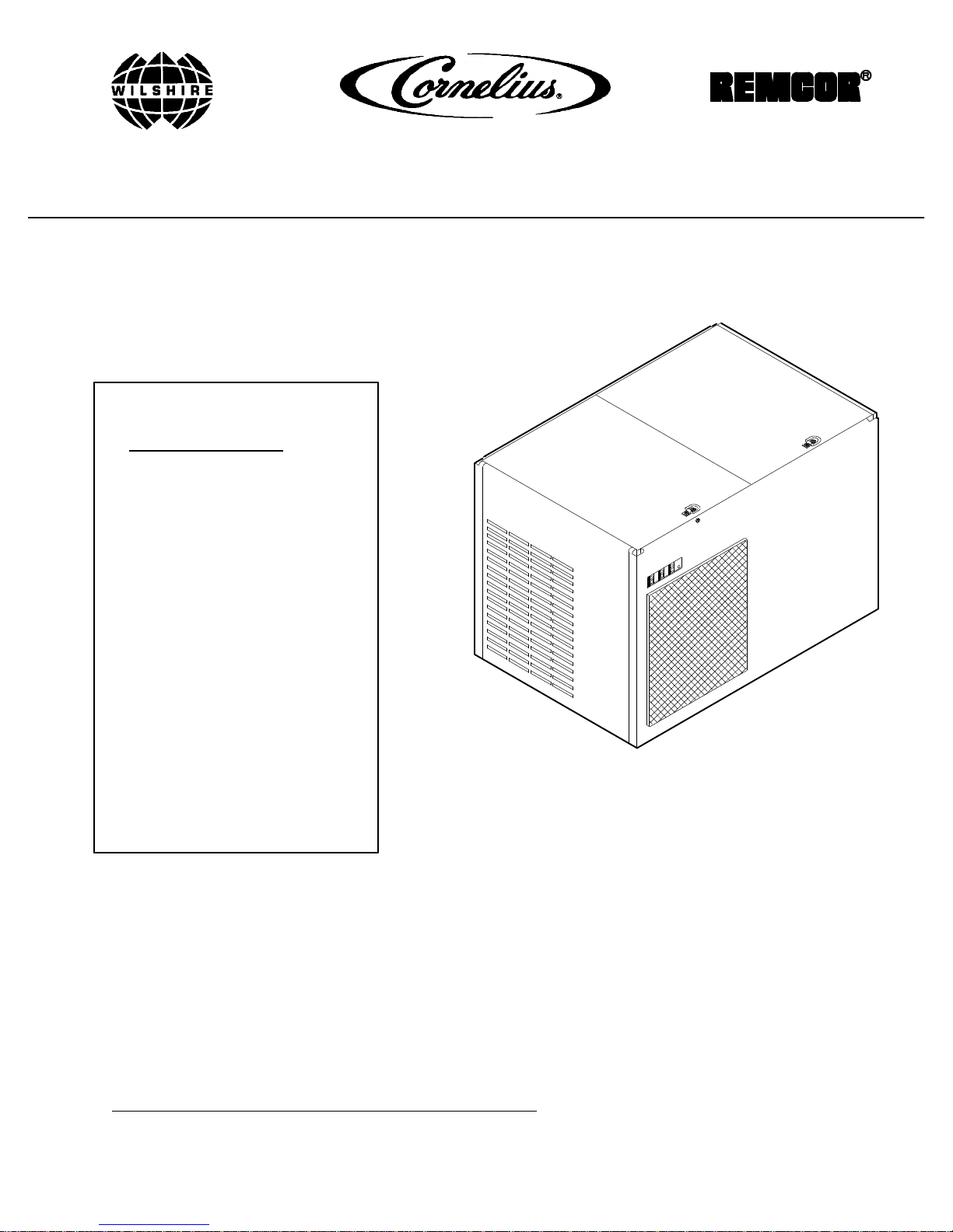
COOLINGUNITWITHINTERNALCONDENSER COILAND FAN
ASSEMBLY15.......................................................
COOLINGUNITCONNECTEDTOREMOTECONDENSER COILAND
FANASSEMBLY16..................................................
DAILY PRE--OPERATION CHECK16.......................................
ADJUSTMENTS16.......................................................
ADJUSTINGCO2REGULATORS16...................................
ADJUSTINGDISPENSINGVALVES WATERFLOWRATE16.............
ADJUSTINGWATER--TO--SYRUP‘‘RATIO’’ OFDISPENSEDPRODUCT16.
ADJUSTINGSIZEOFDRINKDISPENSED16...........................
REPLENISHINGCO2SUPPLY16..........................................
REPLENISHINGSYRUP SUPPLY16.......................................
CLEANINGAND SANITIZING17...........................................
DAILYCLEANING17.................................................
SANITIZINGSYRUP SYSTEMS17.....................................
COOLINGUNITMAINTENANCE17........................................
COOLINGUNITEQUIPPEDWITH CONDENSER COILAND AIR
INTAKE FILTERS17..................................................
COOLINGUNITCARBONATORMAINTENANCE17.....................
COOLINGUNITCARBONATEDWATER CIRCULATINGPUMPMOTOR
LUBRICATION17....................................................
REMOTECONDENSER COILAND FANASS’Y(IFAPPLICABLE)
MAINTENANCE18.......................................................
CLEANINGCO2GAS CHECK VALVES 18..................................
SERVICEAND MAINTENANCE19.............................................
PREPARINGCOOLINGUNIT FORSHIPPING,STORING,OR RELOCATING19
PERIODICINSPECTION19...............................................
REMOTECONDENSER COILAND FANASSEMBLYMAINTENANCE19.......
COOLINGUNITMAINTENANCE20........................................
CLEANINGCOOLINGUNITAIRINTAKE FILTERS20....................
CHECKINGICEWATERBATH20......................................
CHANGINGICEWATERBATH20.....................................
WATERPUMP YEARLYMAINTENANCE(ORAFTERWATERSYSTEM
DISRUPTIONS)23...................................................
ADJUSTMENTS24.......................................................
PRIMARYCO2REGULATOR26.......................................
SECONDARYCO2REGULATORS26..................................
WATERFLOWRATE26..............................................
WATER--TO--SYRUP‘‘RATIO’’ OFDISPENSEDPRODUCT26.............
CLEANINGAND SANITIZING26...........................................
DAILYCLEANING OFUNIT26........................................


 null")