Cornelius 06 1 3601 Series User manual

Product Manual
Model Number Range
06 1 3601XX
06 1 3602XX
Applies to Index remote cooler range:
-Index
21
AC, Air cooled models with part code commencing – 06 1 3601XX
-Index
21
WC, Water cooled models with part code commencing – 06 1 3602XX

Contents
Section Content
1. Introduction
2. Installation Instructions
3. Service Maintenance instructions
4. Fault Finding
5. Product Photos
6. DataSheets
7. Parts Lists and exploded views
8. Wiring Diagrams

1. Introduction
The Index remote cooler is a functional and robust remote cooler, designed with the installer and
service technician in mind. It’s simple and effective operation delivers reduced operating costs
and reduced life costs.
The Index is built to BDA standards, ensuring that the lid is interchangeable, there is simple
exchange of serviceable parts and standard cassette product coils.
Index also has a small footprint, minimising the valuable space taken up in account cellars or
back room
IMI Cornelius is able to offer one of the most extensive ranges of equipment together with a
support package which is second to none.

2. Installation
2.1. Requirements Summary
Installation must be carried out by a suitably trained person and comply with
national and local codes for connection to the electrical supply.
-Unit must be installed indoors on a dry, level surface
-Good ventilation (minimum 100 mm gap around unit)
-Access to side, top and front
-Electrical - 13 amp, 230V
-Grounded, switched (preferably an RCCB)
-Socket within 2m of unit
INDEX 21 AC (air cooled)
-Outside a chilled cellar, close to beer storage
-Ambient temperature 10 to 43°C
INDEX 21 WC (water cooled)
-Base unit inside chilled cellar
-Ambient temperature
oBase unit 10 to 38°C
oHeat Discharge Unit -10 to 35°C
-Maximum distance between base unit and heat discharge unit
o30 metres using 1.5mm2 cable
o50 metres using 2.5mm2 cable
-Glycol Mix- must be pre-mixed before adding to the unit
oGlycol 30% / Water 70% (minimum)
oGlycol 40% / Water 60% (maximum)
-Prepare maximum 12 litres for 50m flow and return of 11.5mm ID
-Minimum glycol flow rate 4.5 litres/min

2.2 Installation Instructions
Please read carefully before installing the unit
Please follow these instructions carefully. Only if the remote unit is properly installed and
maintained will trouble free operation and customer satisfaction be achieved.
General description
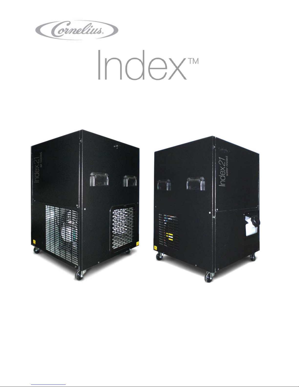
This is a remotely sited cooler used for cooling drinks such as beer, lager, cider & stout.
Incorporating mechanical temperature control this unit is suitable for the utilization of water as
the product cooling medium and for the formation of an ice reserve.
A recirculation pump provides both constant agitation of the water bath and a flow of re-
circulating chilled cooling medium for python cooling. The remote cooler is fully automatic,
therefore, the electrical supply must not be interrupted (unless access for maintenance is
required), otherwise reduced performance and reliability will occur.
Safety
Read this booklet before undertaking installation or maintenance.
Recognize safety alerts – isolate the power supply before removing panels.
DANGER - Indicates an immediate hazardous situation which, if not avoided, WILL result in
serious injury, death, or equipment damage.
WARNING - Indicates an immediate hazardous situation which, if not avoided, COULD result
in serious injury, death, or equipment damage.
CAUTION - Indicates an immediate hazardous situation which, if not avoided, MAY result in
minor or moderate injury, or equipment damage.
Handling & transportation
Keep the remote cooler in an upright position and do not drag over rough floors or down
steps.
Upon receipt, unpack the unit carefully and visually inspect for any damage which may
have been sustained during transit. Record the nature of any damage on the courier’s
delivery note and, at the same time inform your supplier.
Once the unit is in position, do not move when filled with water
Installation
Installation must only be carried out by suitably trained person and must comply with
national and local codes for connection to electrical supplies.
It is recommended that the installation is protected by an RCCB (Residual Current Circuit
Breaker).
Siting
Remote A/C & W/C Units
Remote units are designed for indoor use only.
The remote units may be sited within cooled cellars, store rooms or other appropriate
internal areas where the ambient air temperature is between 5°C and 43°C (A/C), 38°C
(W/C).
Remote coolers should not be exposed to liquid spillage, spray, steam or humidity at a
higher level than 90% rh.
Site the cooler within 40 metre’s of the point of dispense.

Locate the cooler within 2 metre’s of an earthed, switched, 13 Amp, 230V 50Hz socket
which is accessible for isolation of the equipment. The socket must be installed to comply
with current IEE regulations.
Site the cooler on a firm level surface, protect from physical damage and do not place
items on top of, or underneath the cooler.
Clear space must be provided above the unit. Allow 50mm clearance around the unit to
aid air circulation and keep the front of the unit clear to allow an unimpeded air supply to
enter the cooler.
Air vents should never become obstructed or blocked.
Access should be possible to the front panel for ease of service.
Do not stand on this unit.
Installation
General
WARNING - The appliance must be earthed.
If not already fitted, fit the appropriate electrical plug to the service cord. The fuse rating
is stated on the rating plate.
With the unit unpacked and in position, remove all coil caps, but do not connect to an
electrical supply at this stage.
Filling the product water bath.
Do not use de-ionised water or add any substance to the water (unless approved by
Cornelius).
Do not leave hose pipes unattended whilst filling the product water bath as the unit may
become flooded.
Open the filler / inspection hatch on the lid of the cooler.
Fill with cool clean water until liquid starts to flow from the overflow
Stop filling and close the filler / inspection hatch on the lid of the cooler
The overflow is a 15mm connection. A fitting or pipe can be pushed directly into this to
direct the condensate water to drain
Discharge unit (water cooled models)
The discharge cooler should be mounted on an exterior wall, not south facing, and provide
access for pipes and electrical cable to the base unit (maximum 50m). If no exterior wall is
available then mount inside on a wall in a cool room with plenty of fresh air ventilation. Avoid
warm areas (i.e. cupboards or small storerooms). Secure the discharge cooler to the chosen
location and fix (follow instruction guidance from the discharge cooler).
Using a minimum 1.5mm2two core cable, connect the Discharge Cooler to the remote W/C
cooler. Connect the two core cable to the quick fit terminal block, this is located at the rear of the
W/C cooler (Note: This is a nominal 24V 50Hz supply).
Complete the glycol circuit by connecting the pipe work between the remote W/C cooler and the
discharge cooler utilizing 15mm Service Valves.
WARNING - As the glycol lines will circulate a warm glycol mix it is important for safety reasons
that suitable tubing is used. Consult a specialist tubing manufacturer or contact Cornelius.
WARNING - PVC tubing, whether braided or not, is not suitable for this application.

The tubing ID must be sufficient to ensure a minimum flow rate of 4.5 litres/minute in the glycol
circuit. It is recommended that an ID of at least 11.5mm be used. Avoid using elbow joints as
these cause pressure drops.
The tubing must not be routed next to hot surfaces or sharp edges. Avoid ups and downs in each
glycol line as this may create air locks. Do not kink or crush the tubing, ensure minimum bend
radii of 100mm and support where necessary.
WARNING – The lines should never be taped together or insulated.
Priming the discharge unit coolant circuit (water cooled models)
CAUTION – As the python is not connected at this stage disconnect the electrical supply
connection for the recirculation pump from the socket on the rear panel at the back of the cooler.
Mix monopropylene glycol and water to give a solution of Minimum 30% glycol 70% water,
Maximum 40% glycol 60% water.
Glycol should be mixed in a clean container.
CAUTION – Always mix the water : glycol before filling the system.
WARNING - Do not use ethylene glycol.
Ensure sufficient glycol/water mixture is available for filling the coolant bottle and topping up
during priming before switching the remote W/C cooler on.
You will need to prepare:
4 litres of glycol/water mix to fill the water cooled unit coolant system.
In addition the complete system will require topping up with the following quantities to give a
Minimum 30:70 to maximum 40:60 glycol/water ratio whilst priming:
2.1 litres for every 10m of 11.5mm ID tubing
4.2 litres for every 20m of 11.5mm ID tubing
6.3 litres for every 30m of 11.5mm ID tubing
8.4 litres for every 40m of 11.5mm ID tubing
10.5 litres for every 50m of 11.5mm ID tubing
Fill the coolant reservoir to the maximum level (indicated on the front of the coolant reservoir).
CAUTION – ensure all service valves are in the open position prior to switching on the remote
unit
Switch on the mains electrical supply to the remote W/C unit.
As the coolant circuit primes, the level of coolant in the reservoir will drop. Keep filling the
reservoir with the prepared 30:70 / 40:60 glycol/water mixture, ensuring the level does not drop
below the minimum or exceed the maximum levels indicated on the front of the reservoir
CAUTION – do not allow the base mounted coolant pump to run dry.

Connecting the python & product lines.
CAUTION – Ensure the electrical supply connection for the recirculation pump is disconnected
from the socket on the rear panel at the back of the cooler.
If the mains electrical supply to the remote cooler is not already switched on, switch it on now.
CAUTION - All tubing/pythons must be routed to prevent undue stress, tight bends or kinking.
From the product python connect the recirculation lines to the flow and return of the top
mounted recirculation pump on the remote cooler. It is recommended that this connection is
made utilizing 15mm Service Valves to aid with future service requirements.
CAUTION - Ensure the recirculation lines are looped at the point of dispense and plug the
electrical supply lead for the recirculation pump into the socket on the rear panel at the back of
the cooler. Check all plumbing connections for leaks.
As the python recirculation lines prime the level of liquid in the product water bath will drop.
Refer to section ‘Filling the product water bath’ to top up to correct level.
Connect product in and python supply to each connection on the product coils of the remote
cooler. Utilize 3/8” push fit connectors.
Note: All lines to be well insulated to the requirements of the system.
Operation
Once connected to the mains electrical supply allow time for the cooler to build a full icebank
(refer to relevant Product Data Sheet for time to full icebank), the cooler is now ready to use.
Note: there are no user adjustable controls on this remote unit.
Service information
There are no user serviceable items inside the equipment. Maintenance and repairs
must only be carried out by a properly qualified trained person.
Should the unit malfunction, suffer spillage, physical damage or component failure SWITCH OFF
AND UNPLUG THE UNIT FROM THE MAINS ELECTRICAL SUPPLY.
CAUTION – Do not switch the unit ‘off’ and ‘on’ within 5 minutes.
If any maintenance/servicing is required, refer to the fault finding chart, wiring diagram and
exploded drawings contained in the manual.
Only use Cornelius recommended spare parts for cooler maintenance, failure to do so will
invalidate cooler approvals and warranty.
Condenser – It is recommended that the condenser is cleaned with a soft brush or vacuum
cleaner at least every 6 months.
Product water bath – It is recommended that the water in the water bath is replaced annually.
-Melt the ice bank.
-Drain the water bath.
-Refill the water bath.

Description of controls
Refrigeration system reset
The Water Cooled remote utilises a refrigeration system cut out switch. This switch is of manual
reset type and is located in the refrigeration system compartment, behind the removable service
panel.
Upon activation of the switch, diagnose the cause and rectify the problem. Once the problem is
resolved allow 10 minutes then press the Refrigeration System Reset button.
Preventative user maintenance
For all of the below, once the maintenance is carried out, follow the Installation
instructions for re commissioning the unit
Switch off and unplug the unit during user maintenance operations.
In the event of the unit malfunctions or suffers spillage or physical damage, unplug the
unit from its electrical supply.
CAUTION - Do not switch the unit ‘off’ and ‘on’ within five minutes.
Do not attempt to remove the protective covers.
Product water bath level
If the cooler becomes noisy – makes a gurgling sound, this is due to a low product bath water
level and will result in reduced cooling capacity. To remedy this follow the instructions for ‘Filling
the product water bath’
Sanitizing Product Coils
WARNING - Under no circumstances should boiling water or steam be used with this unit
as it may result in permanent damage. The maximum temperature permissible for any
liquid used for sanitising is 40°C.
Sanitize when taste is tainted or periodically as advised by the beverage supplier.
Important flush with potable water, then chlorinated alkaline solution. CAUTION - It is
important that the sanitizing agent manufacturer’s procedure and safety precautions are
followed when using caustic chemicals.
Rinse through with potable water to remove cleaning solution and test with litmus paper.
The 1989 Electricity at Work Regulations require periodic testing of electrical equipment and this
should only be carried out by a competent person.
Directive Compliance:
EMC Directive (2004/108/EC)
Low Voltage Directive (2006/95/EC)
Machinery Directive (89/392/EEC)

3. Service Maintenance Instructions
3.1. INDEX 21 AC
Check that the water level in the water bath is up to the overflow.
Check and clean the rear Condenser fins. Dirt and dust can block the air vents in
the condenser, severely reducing the effectiveness of the refrigeration system.
Check that there is adequate airflow through the unit, ensuring enough space all
round and that there are no obstructions in the front of the air flow vents.
Check ambient temperature is between 10°C and 43°C.
Check the condition and the effectiveness of the Python insulation.
Check for restrictions in the water recirculation python lines (6 ltr per min)
Check for algae growth in the water bath.
At regular intervals, to be determined by the owner and/or the user, the cooler
should be checked for electrical safety.
3.2. INDEX 21 WC
Check that the water level in the water bath is up to the overflow.
Check that the Discharge Unit fan is working and that there are no obstructions
or blockages of the air vents.
Check and clean the heat exchanger fins on the back of the Discharge Unit. Dirt
and dust can block the air vents in the heat exchanger, severely reducing the
effectiveness of the refrigeration system.
Check ambient temperature is between 10°C and 38°C (base unit) -10°C and
35°C (heat discharge unit).
Check the condition and the effectiveness of the Python insulation.
Check the Python for correct water recirculation.
Check for algae growth in the water bath.
At regular intervals, to be determined by the owner and/or user, the cooler should
be checked for electrical safety.
Check the glycol lines are not kinked or crushed. Check for leaks.
Check the strength of the glycol/water mix using a refractometer (20% brix minimum) or
a hydrometer
Check the level of coolant (Water/Glycol) in the reservoir and re-fill as necessary
with a 30% Glycol 70% Water mix using a clean container

4. Fault Finding Chart
Maintenance and repairs must only be carried out by a properly qualified and trained person.
Always switch off and unplug the equipment before servicing or repairing the unit.
PROBLEM POSSIBLE FAULT REMEDY SERVICE TIP
1. Totally Inoperative
Is supply fuse blown or has circuit
breaker tripped? No Loose connection or broken wire in supplying
wiring to unit Replace or reconnect wire Install within 2m of an electrical socket
Yes
Is fuse or circuit breaker size
correct? No Incorrect size device Install correctly sized device See rating plate for current consumption
Yes
Is line voltage within 240v
+6/-10%? Yes Loose connection or broken wire in supply
wiring to unit Replace or reconnect wire Charred connection indicates poorly crimped
electrical connection
No
Is line voltage too high or low? Yes Improper voltage supply Consult electrical supplier Voltage range 207v to 253v
No Unit malfunction Contact IMI Cornelius
2. No Cooling
Is line voltage within 10% of
nameplate voltage? No Go to 1. Totally inoperative Go to 1. Totally inoperative Go to 1. Totally inoperative
Yes
Is compressor cold, fan motor and
green neon on? Yes a) Faulty thermostat
b) Low water
c) Refrigeration system cut out
a) Replace
b) Top up
c) Diagnose cause and reset
a) Do not kink phial tube
b) See install instructions
c) Always isolate electrical supply before
undertaking repairs
No
Compressor doesn’t start, hums
and trips on overload Yes a) Start capacitor shorted or blown
b) Start relay will not close or is burned out
c) Compressor motor is faulty
d) Compressor ceased
a) Check or replace capacitor if required
b) Check connections, replace relay is necessary
c) Replace compressor
d) Replace compressor
a) Check for paper debris of blown capacitor
b) Relay will rattle if OK
c) See rating plate for gas charge
d) Always fit new drier
No
Compressor starts but start winding
does not switch off Yes a) Improper wiring
b) Relay failing to open
c) Excessively high discharge pressure
d) Open or shorted windings in compressor
e) Tight compressor (binding internally)
a) Replace and reconnect wiring
b) Replace relay
c) Clean condenser or replace fan motor
d) Replace compressor
e) Replace compressor
a) Isolate electrical supply before repair
b) Ensure correct relay is used
c) Use vacuum cleaner or soft
d) See rating plate for gas charge
e) Always fit new drier
No
Compressor running hot.
Compressor starts and runs short,
Cycling on overload protector
Yes a) Defective compressor cut out
b) Excessively high discharge pressure
c) Suction gas too hot
d) Low refrigerant charge
a) Replace thermal cut out
b) Clean condenser or replace fan motor
c) Water bath too hot- cool to below 30°c
d) Repair leak and recharge refrigerant
a) Isolate electrical supply before repair
b) Leave 100mm gap around unit
c) n/a
d) Traces of oil are a good indicator of leaks

3. Warm Product
Is compressor running? No Go to 2. No Cooling Go to 2. No Cooling Go to 2. No cooling
Yes
Low water bath level Yes a) Leaks
b) Insufficient water recirculation python
priming
a) Check for leaks and fill to overflow
b) Ensure python is fully primed on install a) Ice build will displace water to the overflow
b) Insufficient python insulation seriously
reduces cooler performance
No
Ice bank build? Yes a) Water recirculation pump not electrically
plugged in or failed
b) Blockage in python
c) Product coil too short
a) Plug pump into socket on the base or replace
failed pump
b) Check for kinks or algae growth
c) Fit longer coil
a) Run cable to ensure cable cannot be
accidentally dislodged in future
b) Add algae inhibitor in the water bath
c) Extra long coil takes up two spaces
No a) High ambient
b) Condenser blocked
c) Defective condenser fan moor assembly
d) Loss of refrigerant charge
e) Incorrectly specified cooler
f) No coolant in glycol tank
g) Coolant base pump failed
h) Coolant not flowing through discharge
cooler
i) Discharge cooler airflow blocked
j) Discharge fan failed
k) Transformer failed
l) Mechanical thermostat failed
m) Poor airflow through condenser
n) Too many coils in the cooler for such a
high demand
o) Product inlet temperature too high
p) Excessive python length
a) Change ambient or re-site cooler
b) Clean condenser grille or remove objects in
front of the condenser which are restricting air
flow into the unit
c) Replace condenser fan motor assembly
d) Check for leaks, repair and recharge
e) Leave for an hour. If ice bank still does not
reform, check specification against location
f) Refill with 30% Glycol, 70% Water.
g) Replace
h) Ensure all valves are open. Check lines are not
kinked or crushed. Ensure pump is primed.
i) Clear blockage. Clean fins as necessary
j) Replace fan motor
k) Replace transformer
l) Replace
m) Clean condenser & ensure adequate space
n) Reduce the number of products on the cooler.
Fit further cooler if necessary
o) Reduce the temperature of product storage
area
p) Limit python length to 40m maximum
(dependent on product throughput)
a) Ensure unit works within ambient range 5-
43°c (A/C) & 5-38°c (W/C)
b) Leave 100mm clearance around unit
c) Unbalanced fans cause motor failures
d) Never leave service valves on cooler
e) 1000 pints per hour peak capacity
theoretically. Python load will reduce this
f) Keep tank full to overflow, check for leaks
g) Refrigeration system cut out isolated the
base mounted coolant pump
h) Never insulate glycol lines & bleed all air.
i) Use 1.5mm2cable to connect discharge
cooler to base cooler
j) Discharge fan runs with compressor
k) Trace wiring to supply at unit to eliminate
possibility of loose connections
l) Ensure new stat Phial is in original position
m) Always leave 100mm air gap
n) Maximum 12 spaces
o) Maximum 43°c (A/C) & 38°c (W/C)
p) Avoid ‘hotspots’ when installing the python,
a separate python cooler maybe necessary.
4. No Product Ice bank too large. Product frozen Erode ice around thermostat with warmer water
(less that 60°c) check and replace thermostat if
faulty
Do not kink phial tube
5. Product too Cold a) Low throughput
b) Coil too long a) Reduce number of taps per product
b) Fit shorter coil a) N/a
b) Short, long or extra long coils available

5. Product Photos
Index21 AC
Heat Dump
Exchange Unit
Index21 WC

6. Product Data sheets
Product data sheet
Index
21
AC
Model 06 1 3601XX
Date: 25 Feb 2010
Issue No: 4
Performance
Nominal icebank pull down:( water 10oC at 24oC ambient) 5 hours
Icebank weight: 25kg nominal
Thermal capacity icebank: 8375KJ (2000 Kcal)
Maximum ambient temperature: 43oC
Dimensions
Height: 930mm
Width: 570mm
Depth: 600mm
Weight: Unloaded 66kg
Packed 67kg
Operational 130kg
Electrical
Mains supply: 230v 1ph 50Hz
Run current: 5.0 amps
Start current: 31 amps
Fuse: 10 amps
Supply: 2m mains cable 3 pin UK
Style plug
Refrigeration
Compressor: 21cc
Compressor starting torque: High starting torque
Compressor duty: (-10oC Evap temp) 750 watts
Evaporator type: 12.7mm dia tube
Condenser type: Air Cooled – Cu/Al construction
Expansion device: Capillary 3M x 1.5mm I.D.
Refrigerant type charge: R134a refer rating plate
Control type: Mechanical thermostat
Fan Motor
Output: 11 watts
Speed: 1300 rpm
Direction: Counter clockwise shaft end
Protection: Impedence
Fan blade: Diameter 250mm
Pitch 28o

Python Pump / Water Bath Agitator
Type: 3-stage semi - submersible
Agitation type: Continuous
Output: 90watts
Speed: 2700rpm
Protection: Thermal trip
Max flow rate @ no pressure: 20 litres per minute
Max lift @ min flow: 18m
Connection size: 15mm diameter tube
Product coils
Length Max Qty
Short: 3.8m 12
Long: 5.4m 12
Super Long: 8.0m 8
Material: 316 stainless steel
Compliance to Standards and Legislation
All coolers comply with Brewers Society Code of Practice for Electrical Safety in Beer Dispense
in License Premises. Designed to EN60335 part1 (Safety of Household and Similar Electrical
Appliances-General Requirements).
Product complies with:
EMC Directive (2004/08/EC)
Low Voltage directive (2006/95/EC)
Machinery Directive (89/392/EEC)

PRODUCT DATA SHEET
Index
21
WC
Model 06 1 3602XX
Date: 25th Feb 2010
Issue No: 5
Performance
Nominal Icebank pull down:( water 10oC at 24oC ambient) 5 hours (max. Icebank)
Icebank weight: 25kg Nominal
Thermal capacity icebank: 8675KJ (2000 Kcal)
Maximum ambient temperature: 38oC
Dimensions Base Unit Discharge Unit
Height: 930mm 360mm
Width: 570mm 460mm
Depth: 600mm 280mm
Weight: Unloaded 69kg 11kg
Packed 70kg 12kg
Operational 137kg 13.5kg
Electrical Base Unit Discharge Unit
Mains supply: 230v 1ph 50Hz 24v 1ph 50Hz
Run current: 6.1 amps
Start current: 31.0 amps
Fuse: 10 amps
Supply: 2m mains cable 3 pin UK
Style plug Min 1.5mm2minimum cable
from base unit (supplied by
Installer)
Refrigeration
Compressor: 21cc
Compressor starting torque: High starting torque
Compressor duty: (-10oC Evap temp) 750 watts
Evaporator type: 12.7mm dia tube
Condenser type: Plate Heat exchanger
Expansion device: Capillary 3M x 1.5mm ID
Refrigerant type charge: R134a refer rating plate
Control type: Mechanical thermostat
Discharge Unit
Heat exchanger: Aluminium fins on copper tube
Fan motor: Output 12 watts
Speed 1250 rpm
Direction Clockwise shaft end
Protection Thermal trip
Fan blade: Diameter 250mm
Pitch 31o
Noise Levels: @ one metre = 61 Decibels @ three metres = 57 Decibels @ five metres = 54 Decibels

Python Pump / Water Bath Agitator
Type: 3-stage semi - submersible
Agitation type: Continuous
Output: 90 watts
Speed: 2700rpm
Protection: Thermal trip
Max flow rate @ no pressure: 20 litres per minute
Max lift @ min flow: 18m
Connection size: 15mm diameter tube
Coolant System
Coolant: Monopropylene Glycol
Coolant mixture: 30% glycol, 70% water
Coolant Pump
3 stage magnetically coupled drive, max lift @ min flow = 15m
Product Coils
Len
g
th Max Qty
Short: 3.8m 12
Long: 5.4m 12
Super Long: 8.0m 8
Material: 316 stainless steel
Other Controls
Refrigeration system cut out Manual reset
Compliance to Standards and Legislation
All coolers comply with Brewers Society Code of Practice for Electrical Safety in Beer Dispense
in License Premises. Designed to EN60335 part1 (Safety of Household and Similar Electrical
Appliances-General Requirements).
Product complies with:
EMC Directive (2004/08/EC)
Low Voltage directive (2006/95/EC)
Machinery Directive (89/392/EEC)

7. Parts Lists and Exploded View
Parts List
Index
21
AC - Model 06 1 3601XX
ITEM PART No. Description
1a 58 0420 589 Totton pump
1b 58 0420 567 Marchmay pump
2 06 0 105108 Inspection panel
3 2RF738A Coil support bar blank
4 06 0 105136 Foamed tank
5 06 0 105113 Handle assy - black
6 06 0 360107 Condenser
6a 06 0 190425 CONDERSER (see alternative view below)
7 58 0900 086 Comp set sc21f - danfoss
7a 3DF001A Compressor start relay - danfoss
7b 58 0420 143 Compressor start capacitor - danfoss
8 06 0 274007 Fan motor mod’d
9 06 0 361107 Fan motor bracket
9a 220104050 Fan cowl moulded (see alternative view below)
10 44 0000 058 Fan blade
11 58 1174 007 Icebank thermostat - mechanical
11a 58 0400 100 Variable stat (not shown)
11b 58 0475 059 Knob – variable stat (not shown)
12 58 0475 214 Lifting handle - lid
13 06 0 361104 Coil clamp
14 58 0440 438 Neon – green
15 58 0446 146 Socket – snap fit female
16 58 0480 145 Castor 2” mercury swivel
17a 06 0 100107 Coil assy LG 9.5 x 5.0M: max 12 coils
17b 06 0 100137 Coil assy SH 9.5 x 3.8M: max 12 coils
17c 06 0 100138 Coil assy LG 9.5 x 8.0M: max 8 coils
6a
9a
10
8
A
LTERNATIVE CONDENSOR ARRANGEMENT

ExplodedView
Index
21
AC
Model 06 1 3601XX
1
2
4
6
7 8
11
3
5 10
12
14
15
16
17
9
13

Parts list
Index 21 wc
Model 06 1 3602xx
Item Part no. Description
1a 58 0420 589 Totton pump
1b 58 0420 567 Marchmay pump
2 06 0 105143 Glycol bottle
3 2rf738a Coil support bar blank
4 06 0 105136 Foamed tank
5 06 0 105113 Handle assy - black
6 Cm011514s ½” bsp to 15.0mm jg fitting
7 58 0900 086 Comp set sc21f - danfoss
7a 3df001a Compressor start relay - danfoss
7b 58 0420 143 Compressor start capacitor - danfoss
8 58 0440 429 Transformer
9a 58 0420 610 Glycol pump totton
9b 58 0420 570 Glycol pump marchmay
10 58 0446 198 24v connector
11 58 1174 007 Icebank thermostat - mechanical
12 58 0475 214 Lifting handle - lid
13 58 0400 163 Pressure switch
14 58 0450 115 Plate heat exchanger
15 06 0 361104 Coil clamp
16 58 0440 438 Neon – green
17 58 0446 146 Socket – snap fit female
18 58 0480 145 Castor 2” mercury swivel
N/s 2mc824a Glycol bottle 4 ltr
19 15isv Ball valve 15mm
20a 06 0 100107 Coil assy lg 9.5 x 5.0m: max 12 coils
20b 06 0 100137 Coil assy sh 9.5 x 3.8m: max 12 coils
20c 06 0 100138 Coil assy lg 9.5 x 8.0m: max 8 coils
This manual suits for next models
1
Table of contents
Other Cornelius Air Conditioner manuals
Popular Air Conditioner manuals by other brands

Innova
Innova Innova Filomuro Incasso SLWI Installation and user manual

GE
GE ASQ12AL Dimensions and installation information

Mitsubishi Electric
Mitsubishi Electric PEAD-42AA5 installation manual

REMKO
REMKO SKT 521 Operating and installation instructions

Samsung
Samsung AR Series user manual

Mitsubishi Electric
Mitsubishi Electric City Multi PLFY-WL-VEM-E Series installation manual