Cornelius Energize 1 HC Series Manual

Installation and service manual
Undercounter cooler
Energize 1 HC

Legal notice
Installation and service manual (Original)
Document no. TD1001100
Undercounter cooler
Unit ID no. 221001100
Energize 1 HC
Version
Date of issue: 03/08/2018
Revision status: Index 2
www.cornelius-emea.com Cornelius Deutschland GmbH
Carl-Leverkus-Str. 15
40764 Langenfeld
Germany
Tel.: +49 (0) 21 73 / 79 3 – 0
Fax: +49 (0) 21 73 / 77 4 – 38
E-Mail: info@cornelius.com
Protection notices (in accordance with DIN ISO 16016:2017-08)
The reproduction, distribution and utilisation of this document as well as the communication of its contents is prohibited, unless
expressly permitted. Violations shall result in an obligation to pay damages. All rights reserved with regard to filing for/registering
patents, utility models or design patents.

Cornelius Deutschland GmbH
Document no. TD1001100
Version 03/08/2018, Index 2
Installation and service manual Undercounter cooler
Energize 1 HC
1
Installation and service manual
Undercounter cooler
Table of contents
1 Safety . . . . . . . . . . . . . . . . . . . . . . . . . . . . . . . . . . . . . . . . . . . . . . . . . . . . . . . . . . . . . . . . . . . . . . . . 3
1.1 Intended use . . . . . . . . . . . . . . . . . . . . . . . . . . . . . . . . . . . . . . . . . . . . . . . . . . . . . . . . . . . . . . . . . . . . 3
1.2 Improper use. . . . . . . . . . . . . . . . . . . . . . . . . . . . . . . . . . . . . . . . . . . . . . . . . . . . . . . . . . . . . . . . . . . . 3
1.3 Staff. . . . . . . . . . . . . . . . . . . . . . . . . . . . . . . . . . . . . . . . . . . . . . . . . . . . . . . . . . . . . . . . . . . . . . . . . . 3
1.4 Presentation of warnings . . . . . . . . . . . . . . . . . . . . . . . . . . . . . . . . . . . . . . . . . . . . . . . . . . . . . . . . . . . . 3
1.5 Safety information . . . . . . . . . . . . . . . . . . . . . . . . . . . . . . . . . . . . . . . . . . . . . . . . . . . . . . . . . . . . . . . . 3
1.5.1 Safety information to prevent personal injury and equipment damage . . . . . . . . . . . . . . . . . . . . . . . . . . . . . . 3
1.5.2 Safety information for using electrical assemblies . . . . . . . . . . . . . . . . . . . . . . . . . . . . . . . . . . . . . . . . . . . 3
2 Transport and packaging . . . . . . . . . . . . . . . . . . . . . . . . . . . . . . . . . . . . . . . . . . . . . . . . . . . . . . . . . . 5
2.1 Storage . . . . . . . . . . . . . . . . . . . . . . . . . . . . . . . . . . . . . . . . . . . . . . . . . . . . . . . . . . . . . . . . . . . . . . . 5
2.2 Disposal . . . . . . . . . . . . . . . . . . . . . . . . . . . . . . . . . . . . . . . . . . . . . . . . . . . . . . . . . . . . . . . . . . . . . . . 5
3 Description . . . . . . . . . . . . . . . . . . . . . . . . . . . . . . . . . . . . . . . . . . . . . . . . . . . . . . . . . . . . . . . . . . . . 6
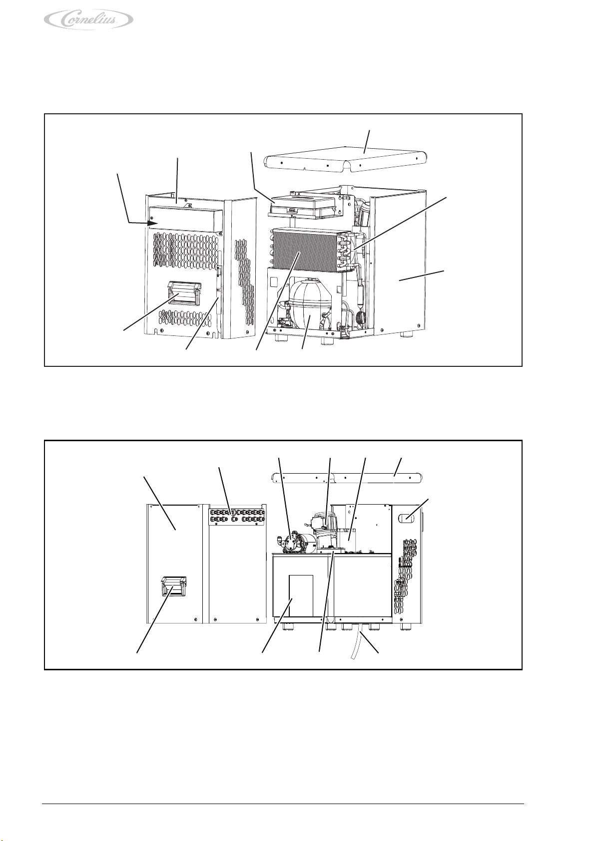
3.1 Assemblies and components . . . . . . . . . . . . . . . . . . . . . . . . . . . . . . . . . . . . . . . . . . . . . . . . . . . . . . . . . 6
3.2 Functions within the dispensing system . . . . . . . . . . . . . . . . . . . . . . . . . . . . . . . . . . . . . . . . . . . . . . . . . . 7
3.3 Functions of the unit . . . . . . . . . . . . . . . . . . . . . . . . . . . . . . . . . . . . . . . . . . . . . . . . . . . . . . . . . . . . . . . 7
3.4 Technical data . . . . . . . . . . . . . . . . . . . . . . . . . . . . . . . . . . . . . . . . . . . . . . . . . . . . . . . . . . . . . . . . . . . 8
3.4.1 Undercounter cooler . . . . . . . . . . . . . . . . . . . . . . . . . . . . . . . . . . . . . . . . . . . . . . . . . . . . . . . . . . . . . . . 8
3.4.2 Labelling positions . . . . . . . . . . . . . . . . . . . . . . . . . . . . . . . . . . . . . . . . . . . . . . . . . . . . . . . . . . . . . . . . 8
3.4.3 CO2 working pressures . . . . . . . . . . . . . . . . . . . . . . . . . . . . . . . . . . . . . . . . . . . . . . . . . . . . . . . . . . . . . 8
3.4.4 Connections . . . . . . . . . . . . . . . . . . . . . . . . . . . . . . . . . . . . . . . . . . . . . . . . . . . . . . . . . . . . . . . . . . . . 9
4 Preparing the unit. . . . . . . . . . . . . . . . . . . . . . . . . . . . . . . . . . . . . . . . . . . . . . . . . . . . . . . . . . . . . . . . 10
4.1 Disconnecting the unit from power. . . . . . . . . . . . . . . . . . . . . . . . . . . . . . . . . . . . . . . . . . . . . . . . . . . . . . 10
5 Installation/removal . . . . . . . . . . . . . . . . . . . . . . . . . . . . . . . . . . . . . . . . . . . . . . . . . . . . . . . . . . . . . . 12
5.1 Installation location. . . . . . . . . . . . . . . . . . . . . . . . . . . . . . . . . . . . . . . . . . . . . . . . . . . . . . . . . . . . . . . . 12
5.2 Installing the unit . . . . . . . . . . . . . . . . . . . . . . . . . . . . . . . . . . . . . . . . . . . . . . . . . . . . . . . . . . . . . . . . . 12
5.3 Removing the unit . . . . . . . . . . . . . . . . . . . . . . . . . . . . . . . . . . . . . . . . . . . . . . . . . . . . . . . . . . . . . . . . 13
6 Maintenance . . . . . . . . . . . . . . . . . . . . . . . . . . . . . . . . . . . . . . . . . . . . . . . . . . . . . . . . . . . . . . . . . . . 14
6.1 Maintenance table . . . . . . . . . . . . . . . . . . . . . . . . . . . . . . . . . . . . . . . . . . . . . . . . . . . . . . . . . . . . . . . . 14
6.2 Cleaning the tubes . . . . . . . . . . . . . . . . . . . . . . . . . . . . . . . . . . . . . . . . . . . . . . . . . . . . . . . . . . . . . . . . 14
6.3 Changing the water in the water bath. . . . . . . . . . . . . . . . . . . . . . . . . . . . . . . . . . . . . . . . . . . . . . . . . . . . 14
6.4 Cleaning the condenser fins. . . . . . . . . . . . . . . . . . . . . . . . . . . . . . . . . . . . . . . . . . . . . . . . . . . . . . . . . . 15
6.5 Bleeding the carbonator tank . . . . . . . . . . . . . . . . . . . . . . . . . . . . . . . . . . . . . . . . . . . . . . . . . . . . . . . . . 15
6.6 Thawing the ice build-up . . . . . . . . . . . . . . . . . . . . . . . . . . . . . . . . . . . . . . . . . . . . . . . . . . . . . . . . . . . . 15
7Repairs
. . . . . . . . . . . . . . . . . . . . . . . . . . . . . . . . . . . . . . . . . . . . . . . . . . . . . . . . . . . . . . . . . . . . . . . 16
7.1 Replacing the cover . . . . . . . . . . . . . . . . . . . . . . . . . . . . . . . . . . . . . . . . . . . . . . . . . . . . . . . . . . . . . . . 16
7.2 Replacing the sheet casing (service) . . . . . . . . . . . . . . . . . . . . . . . . . . . . . . . . . . . . . . . . . . . . . . . . . . . . 17
7.3 Replacing the connecting plate . . . . . . . . . . . . . . . . . . . . . . . . . . . . . . . . . . . . . . . . . . . . . . . . . . . . . . . . 18
7.4 Replacing the agitator motor . . . . . . . . . . . . . . . . . . . . . . . . . . . . . . . . . . . . . . . . . . . . . . . . . . . . . . . . . 18
7.5 Replacing the circulation pump . . . . . . . . . . . . . . . . . . . . . . . . . . . . . . . . . . . . . . . . . . . . . . . . . . . . . . . . 19
7.6 Replacing the carbonator pump . . . . . . . . . . . . . . . . . . . . . . . . . . . . . . . . . . . . . . . . . . . . . . . . . . . . . . . 19
7.7 Replacing the carbonator tank . . . . . . . . . . . . . . . . . . . . . . . . . . . . . . . . . . . . . . . . . . . . . . . . . . . . . . . . 20
7.8 Replacing the control system mounting plate. . . . . . . . . . . . . . . . . . . . . . . . . . . . . . . . . . . . . . . . . . . . . . . 21
7.9 Replacing the control system . . . . . . . . . . . . . . . . . . . . . . . . . . . . . . . . . . . . . . . . . . . . . . . . . . . . . . . . . 21
7.10 Replacing the mains filter . . . . . . . . . . . . . . . . . . . . . . . . . . . . . . . . . . . . . . . . . . . . . . . . . . . . . . . . . . . 22
7.11 Replacing the fans . . . . . . . . . . . . . . . . . . . . . . . . . . . . . . . . . . . . . . . . . . . . . . . . . . . . . . . . . . . . . . . . 22
7.12 Replacing the run capacitor for the carbonator pump . . . . . . . . . . . . . . . . . . . . . . . . . . . . . . . . . . . . . . . . . 23
7.13 Replacing the condenser . . . . . . . . . . . . . . . . . . . . . . . . . . . . . . . . . . . . . . . . . . . . . . . . . . . . . . . . . . . . 24
7.14 Replacing the starting capacitor . . . . . . . . . . . . . . . . . . . . . . . . . . . . . . . . . . . . . . . . . . . . . . . . . . . . . . . 24
7.15 Replacing the starter relay . . . . . . . . . . . . . . . . . . . . . . . . . . . . . . . . . . . . . . . . . . . . . . . . . . . . . . . . . . . 25
7.16 Replacing the overload protection . . . . . . . . . . . . . . . . . . . . . . . . . . . . . . . . . . . . . . . . . . . . . . . . . . . . . . 26

Cornelius Deutschland GmbH
Document no. TD1001100
Version 03/08/2018, Index 2
Installation and service manual Undercounter cooler
Energize 1 HC
2
8 Commissioning/shutdown. . . . . . . . . . . . . . . . . . . . . . . . . . . . . . . . . . . . . . . . . . . . . . . . . . . . . . . . . . 27
8.1 Commissioning . . . . . . . . . . . . . . . . . . . . . . . . . . . . . . . . . . . . . . . . . . . . . . . . . . . . . . . . . . . . . . . . . . 27
8.2 Shutdown . . . . . . . . . . . . . . . . . . . . . . . . . . . . . . . . . . . . . . . . . . . . . . . . . . . . . . . . . . . . . . . . . . . . . . 28
9 Errors and malfunctions . . . . . . . . . . . . . . . . . . . . . . . . . . . . . . . . . . . . . . . . . . . . . . . . . . . . . . . . . . . 29
9.1 Troubleshooting table . . . . . . . . . . . . . . . . . . . . . . . . . . . . . . . . . . . . . . . . . . . . . . . . . . . . . . . . . . . . . . 29
10 Applicable documents . . . . . . . . . . . . . . . . . . . . . . . . . . . . . . . . . . . . . . . . . . . . . . . . . . . . . . . . . . . . 31
10.1 Flowchart . . . . . . . . . . . . . . . . . . . . . . . . . . . . . . . . . . . . . . . . . . . . . . . . . . . . . . . . . . . . . . . . . . . . . . 31
10.2 Undercounter cooler cable diagram . . . . . . . . . . . . . . . . . . . . . . . . . . . . . . . . . . . . . . . . . . . . . . . . . . . . . 32

Safety
Cornelius Deutschland GmbH
Document no. TD1001100
Version 03/08/2018, Index 2
Installation and service manual Undercounter cooler
Energize 1 HC
3
1Safety
1.1 Intended use
By using the unit as intended you will not only protect yourself, but also prevent damage occurring to the unit and its components!
You can find further information about the intended use of the unit in the undercounter cooler operator manual, document no.
TD1001000.
1.2 Improper use
Improper use of the unit and unauthorised modifications to the unit and its components may cause personal injury and equipment
damage for which Cornelius Deutschland GmbH shall assume no liability. Improper use of the unit is prohibited.
You can find further information about the improper use of the unit – and the meaning of improper use – in the undercounter cooler
operator manual, document no. TD1001000.
1.3 Staff
There is a clear definition as to what group of people is permitted to carry out what type of work on the unit. You can find further
information about who is authorised to carry out what type of work on the unit in the undercounter cooler operator manual, docu-
ment no. TD1001000.
1.4 Presentation of warnings
The documents supplied with the unit provide warnings regarding any dangers or hazards that might exist. You can find more in-
formation about the design and presentation of warnings in the undercounter cooler operator manual, document no. TD1001000.
1.5 Safety information
1.5.1 Safety information to prevent personal injury and equipment damage
Any work on the unit and its components which goes beyond operation and beyond the servicing and maintenance tasks that the
operator is authorised for, may only be performed by experts (for a definition of experts, see the undercounter cooler operator
manual, document no. TD1001000). Furthermore, it is crucial that when performing work on the unit all safety information is ob-
served; this information is set out in the following sections. Some of the tasks may have additional safety information which high-
lights the specific dangers or hazards associated with such work.
1.5.2 Safety information for using electrical assemblies
DANGER!
To prevent risks to health and safety, please always observe the following five safety rules:
These five safety rules are to be applied before carrying out work on the electrical system and in the order stated
below. Once work is completed, the safety rules are to be undone again in reverse order.
• 1. Disconnect from power.
• 2. Secure against reconnection.
• 3. Check that the system is disconnected from power.
• 4. Ground and short-circuit the system.
• 5. Cover or separate adjacent live parts.
WARNING!
Risk of burns when touching hot parts of the unit!
Touching parts of the unit after it has been in continuous use over an extended period of time will result in a risk
of burns.
• Take appropriate safeguard measures, such as by wearing heat-resistant protective gloves.
DANGER!
Risk of poisoning and risk of explosion due to improper handling of CO2 cylinders
Risk of death from CO2!
• Observe all information on occupational safety for the safe operation of dispensing systems as applicable
in the relevant country of installation.
NOTICE!
• Make sure that the cable markers are not removed from the cables and/or mark or label the cables such
that they can be correctly assigned during installation.

Safety
Cornelius Deutschland GmbH
Document no. TD1001100
Version 03/08/2018, Index 2
Installation and service manual Undercounter cooler
Energize 1 HC
4
ATTENTION!
Cables must be fixed in place using cable ties.
When fixing cables in place using cable ties, observe the following points:
• Once work on the unit is completed, return the area to the same state that you found it in.
• Using cable ties, combines cables in a meaningful way.
• When installing cables, be mindful of any bending radiuses that the manufacturer may have specified.
• To fix cables in place using cable ties, use the mounting bases provided.

Transport and packaging
Cornelius Deutschland GmbH
Document no. TD1001100
Version 03/08/2018, Index 2
Installation and service manual Undercounter cooler
Energize 1 HC
5
2 Transport and packaging
Choose a suitable packaging when returning the unit itself or one of its components to Cornelius Deutschland GmbH, e.g. for re-
pairs. In particular, make sure that the unit and any components are protected from shock/impact, moisture, dirt and electrostatic
discharge (ESD). This will prevent transport damage to the unit and to the components, for which the manufacturer shall assume
no liability.
ATTENTION!
Component damage due to freezing liquids!
Ambient temperatures that are below freezing will lead to the freezing of any water or cleaning agent residue
remaining inside the unit. This will lead to damage to internal components.
• Before shipment, storage or relocation of the unit, the unit is to be cleaned and the cleaning solution is to
be fully drained from the unit.
2.1 Storage
Avoid excessive temperature fluctuations as condensate may form, which in turn may cause damage to the unit or to the compo-
nents.
The permissible storage temperature is -10 °C to +50 °C.
The acclimatisation period is 6 hours.
ATTENTION!
Damage due to improper storage!
Dirt or moisture entering a unit, as well as certain weather conditions (e.g. condensate forming in the unit, sun-
light) will cause damage to the unit and its components.
• Protect the unit and its components by storing the unit in a clean and dry place, and by ensuring stable
ambient conditions.
• If possible, store the unit in its original packaging. Unpacked units must be covered with a dustproof cover.
No condensate must form under the cover.
ATTENTION!
Risk of electrostatic charge!
Improper handling or storage may result in electrostatic charges.
• If possible, store units and/or any electronic components in their original packaging.
• Keep units and/or electronic components away from charged objects, fields and insulators.
• Avoid electrostatic charges when removing packaging and/or handling electronic assemblies and compo-
nents by working at an ESD-protected workstation or work area.
• When working at the unit or its components, wear a grounding (antistatic) wrist strap at the very least and
wear antistatic gloves if necessary.
ATTENTION!
Component damage due to material ageing!
Material can age due to long storage periods, thereby affecting the material’s properties (e.g. plastics and seals
may become brittle). The properties of lubricants may change due to long storage periods.
• Check the assemblies and components for damage before each use/before installing them. Do not install
assemblies or components that show visible signs of ageing.
2.2 Disposal
Disposal of the units must be carried out in compliance with the applicable local and/or national and international regulations. Units
must not be disposed of with household waste.
If the unit contains fuels or lubricants in liquid, paste-like or gaseous form, such as oil, grease, cooling agents etc., such fuels or
lubricants are to be collected using appropriate measures and disposed of in compliance with the applicable local and/or national
and international regulations. Such fuels or lubricants must always be prevented from seeping into the ground, the sewage system
and any bodies of water, and must always be prevented from entering the atmosphere.

Description
Cornelius Deutschland GmbH
Document no. TD1001100
Version 03/08/2018, Index 2
Installation and service manual Undercounter cooler
Energize 1 HC
6
3 Description
3.1 Assemblies and components
The housing accommodates all assemblies and components.
The unit comprises the following assemblies:
Fig. 1
Fig. 2
1
23
4
5
6
7
8
9
10
1 Mains filter
2 Sheet casing (service)
3 Control system
4Cover
5Fan
6 Sheet casing (fixed)
7 Refrigerant compressor
8 Condenser
9 Water level gauge
10 Carry handle
1
2
3 4 56
7
8
9
10
11
1 Sheet casing (fixed)
2 Connecting plate with tube connections
3 Carbonator pump
4 Agitator motor
5 Circulation pump
6Cover
7 Control and indicator panel
8Overflow
9 Carbonator tank
10 Water bath
11 Carry handle

Description
Cornelius Deutschland GmbH
Document no. TD1001100
Version 03/08/2018, Index 2
Installation and service manual Undercounter cooler
Energize 1 HC
7
3.2 Functions within the dispensing system
NOTICE!
The description of how the unit works within the dispensing system is included in the relevant operator manual
for this unit; see the document “Undercounter cooler operator manual”, document no. TD1001000.
3.3 Functions of the unit
NOTICE!
Flowchart; see chapter 10.1
The three basic functions of the unit are:
– Refrigeration
– Carbonisation
– Conveying
All functions are controlled by the requests at the tower or by the sensor logic of the unit’s internal control system.
The carbonator pump forces the mains water into the carbonator tank at a constant pressure.
The water in the carbonator tank has CO2 added to it to produce soda. The circulation pump keeps the chilled soda circulating in
the secondary refrigeration system to the tower.
Ice is built up in the water bath to refrigerate the products. The agitator keeps the products refrigerated. The ice build-up sensor
prevents excessive freezing of the ice build-up.
Cold generator
A cold generator refrigerates the water bath by means of a heat exchanger. In the process, a defined ice build-up is generated
around the heat exchanger.
To stop the water bath from freezing up and to maintain more efficient heat exchange, an agitator constantly agitates the cooling
water.
Once the unit has been filled with water, the refrigerant compressor automatically starts up after 3 minutes if the compressor is in
position “I”. Once the maximum ice build-up has been achieved, the refrigerant compressor automatically switches off.
In ice build-up mode, certain minimum runtimes and operation intervals arise. After switching on the refrigeration circuit, the run-
time is at least 5 minutes, even if a shutdown has been signalled beforehand. After switching off the refrigeration circuit, the oper-
ation intervals are at least 3 minutes, even if switching on has been signalled beforehand. The operation intervals of 3 minutes
also apply to start-up or after a power failure.
Control system and sensor logic
There is a sensor for the water level in the carbonator tank, a probe for controlling the ice build-up, the hot gas probe for the re-
frigerating unit and an ambient temperature probe.
If CO2 pressure is insufficient in the carbonator tank, a yellow LED on the control unit will visually indicate that the pressure is too
low (< 0.4 MPa).
The tower power supply is cut off in good time to prevent the carbonator tank being pumped empty. Once the carbonator tank has
been refilled, the power supply is automatically switched on again.
If the fill level drops below the minimum, the carbonator pump will automatically switch on and fill the carbonator tank.
The carbonator pump switches off when the carbonator tank has been filled to maximum, or after 20 minutes at the latest. Longer
runtimes indicate leaks or excessive beverage dispensing. The pump can only be restarted by a reset (temporarily unplugging the
mains plug for approx. 10 seconds).
Water supply
The system’s drinking water supply is provided by the mains water which flows through a pressure-reducing valve and filter to the
carbonator pump on the unit’s connecting plate. If still water is requested at the tower, the water flows via a heat exchanger in the
refrigerated water bath to the tower.
To ensure the water stays chilled, even in the breaks between dispensing, a circulation pump in the unit constantly recirculates the
water via a heat exchanger in the water bath.
CO2 connection
The CO2 is supplied by the pressurised gas cylinder and pressure-reducing valve to the unit’s CO2 connection.
Only for types with CO2-operated syrup pumps:
In the case of CO2 operated syrup pumps, CO2 is supplied separately by the pressurised gas cylinder through a dual pressure-
reducing valve to the syrup pumps for the supply of standard basic ingredients, and to the syrup pump for the supply of the basic
ingredient for reduced calorie (‘light’) products.
Soda and still water connection
The soda is connected to the flow and return connections of the soda water circuit on the unit’s connecting plate.
Still water is connected at the unit’s still water outlet.
Syrup supply
The syrup containers are connected directly to the syrup connections on the unit.
The BiBs are connected to the syrup pumps and from there to the syrup connections on the unit.

Description
Cornelius Deutschland GmbH
Document no. TD1001100
Version 03/08/2018, Index 2
Installation and service manual Undercounter cooler
Energize 1 HC
8
3.4 Technical data
3.4.1 Undercounter cooler
3.4.2 Labelling positions
NOTICE!
The applicable operator manual includes illustration of the labelling positions for this unit; see the document
“Undercounter cooler operator manual”, document no. TD1001000.
3.4.3 CO2 working pressures
NOTICE!
The applicable operator manual for this unit includes specifications for the CO2 working pressures for the unit;
see the document “Undercounter cooler operator manual”, document no. TD1001000.
Description Parameter Value Unit
Dimensions Height 510/20.1 mm/in.
Width 341/13.4 mm/in.
Depth 590/23.2 mm/in.
Dispensing capacity At a dispensing rate of 2 drinks of
0.3 litres a minute1
105 Unit
Ice build-up size Weight 5.4 kg
Ice build-up capacity 432 kcal/h
Ice build-up (No python) 95 min.
Refrigerant Propane R290 0.080 kg
Power supply Supply voltage 230 V
Frequency 50 Hz
Power input max. 360 W
Current consumption max. 1.6 A
Compressor Output 291 (1/5) W (hp)2
Carbonator pump capacity at 0.2 MPa 220 L/h
Circulation pump capacity at 0.2 MPa 100 L/h
Python length max. 2 m
Cooling capacity3/
in the working range
317 W
242 kcal/h
Number of cooling coils max. 6xPOM Unit
Shipping weight 40 kg
1. with 10 m SC python
2. at -10 °C evaporation temperature
3. Specifications on cooling capacity and dispensing capacity 24 °C ambient temperature, syrup intake temperatures of 18 °C, water intake temperatures of 18 °C and beverage dis-
pensing temperatures < 5 °C

Description
Cornelius Deutschland GmbH
Document no. TD1001100
Version 03/08/2018, Index 2
Installation and service manual Undercounter cooler
Energize 1 HC
9
3.4.4 Connections
Fig. 3
9 8 7 6 5 4 3 2
10 1
Item Designation Medium Connection size
1 Syrup 1...6 Syrup tubes 1-6 (input) 1/4" ID and 3/8" OD
2 Supply Soda water circulation (supply) 3/8" ID and 1/2" OD
3 Return Soda water circulation (return) 3/8" ID and 1/2" OD
4 Still water Still water dispenser 1/4" ID and 3/8" OD
5 Premix not assigned 1/4" ID and 3/8" OD
6 W. input Drinking water connection 3/8" ID and 1/2" OD
7 Cable Cable duct for still water control system 16 mm
8 Premix not assigned 1/4" ID and 3/8" OD
9CO
2 in. CO2 supply for carbonation 3/8" ID and 1/2" OD
10 Syrup 1...6 Syrup tubes 1-6 (output) 1/4" ID and 3/8" OD

Preparing the unit
Cornelius Deutschland GmbH
Document no. TD1001100
Version 03/08/2018, Index 2
Installation and service manual Undercounter cooler
Energize 1 HC
10
4 Preparing the unit
DANGER!
Risk of personal injury and equipment damage due to non-compliance with safety information!
Failure to observe the safety information will result in a risk of bringing about operating conditions at the unit,
which may cause personal injury or equipment damage.
• Please always strictly observe all safety measures and information/instructions; see chapter 1.
This chapter describes the tasks that may be required before carrying out any actual maintenance or repair work.
DANGER!
You may only continue working on the unit if the unit carries no voltage.
If the unit still carries a voltage after you have disconnected it from power, this indicates a defect. Resolve this
defect before continuing the checks/inspections or any work.
4.1 Disconnecting the unit from power
ATTENTION!
Risk of death from electric shock!
The mains plug may still have residual current.
• Wait a minimum of 1 minute before continuing work on the unit.
ATTENTION!
Risk of equipment damage!
A direct “low ohm” discharge may cause equipment damage.
• Discharge the components properly.
Prerequisites References
The tower has been shut down. See the document “Tower operator manual”
Required tools/materials ID/
reference
Qty/
amount
Comment
Undercounter cooler cable diagram 220046687 1 see chapter 10.2
Tower operator
manual
Document no:
various
1
Multimeter Various 1 Safety category CAT II
1. Turn the compressor switch (Fig. 4/1) to position “0”.
2. Turn the circulation pump switch (Fig. 4/2) to position “0”.
3. Turn the carbonator pump switch (Fig. 4/3) to position “0”.
Fig. 4
1 2 3
4. Pull the mains plug out of the earthed socket.
Fig. 5

Preparing the unit
Cornelius Deutschland GmbH
Document no. TD1001100
Version 03/08/2018, Index 2
Installation and service manual Undercounter cooler
Energize 1 HC
11
5. Discharge the condensers as follows:
a) Disconnect the AC power line (Fig. 6/1) from the unit.
b) Switch the multimeter to alternating voltage.
Fig. 6
1
c) Measure the voltage at the unit mains connection (Fig. 6/1) using a multimeter.
Make sure the voltage drops to a value of 0 V in the process.
d) Only continue working on the unit once the unit is fully discharged of voltage.
Fig. 7
1

Installation/removal
Cornelius Deutschland GmbH
Document no. TD1001100
Version 03/08/2018, Index 2
Installation and service manual Undercounter cooler
Energize 1 HC
12
5 Installation/removal
DANGER!
Risk of personal injury and equipment damage due to non-compliance with safety information!
Failure to observe the safety information will result in a risk of bringing about operating conditions at the unit,
which may cause personal injury or equipment damage.
• Please always strictly observe all safety measures and information/instructions; see chapter 1.
NOTICE!
All installation, maintenance and repair work at the unit is to be carried out by an expert only.
WARNING!
Risk of personal injury and equipment damage due to operation by non-qualified staff!
It is dangerous for non-qualified staff to operate the unit!
• Service operations on this unit may only be carried out by trained and certified experts who have been
trained in carrying out service operations on this unit.
• All wiring and plumbing must be carried out in compliance with national and local laws, regulations and
guidelines. Non-compliance with these laws, regulations and guidelines may result in death, serious injury
or equipment damage.
5.1 Installation location
NOTICE!
Observe all rules and regulations regarding installation rooms and electric connections as applicable in the in-
dividual countries, as well as accident prevention regulations.
ATTENTION!
Damage due to inadequate ventilation!
If the unit is inadequately ventilated, it will overheat and become damaged.
• During installation of the unit, make sure the site of installation is adequately ventilated.
• Always make sure that the supply and exhaust air grilles are not covered.
• When installing the unit, keep a minimum distance of 30 cm from objects or walls.
The unit must be set up and installed close to an earthed mains socket. The electric circuit must be fuse-protected, and no addi-
tional units or devices must be connected to the electric circuit.
All connections and outlets/drains must comply with the applicable local and/or national and international regulations.
5.2 Installing the unit
Prerequisites References
The unit has been unpacked. See the document “Undercounter cooler operator manual”,
document no. TD1001000
The cover has been removed. see chapter 7.1
The CO2 bottle has been set up properly. See the document on the CO2 system.
The pressure-reducing valves have been mounted on the CO2
bottle.
See the document on the CO2 system.
The pressure-reducing valves have been mounted on the water
supply line.
See the document on the drinking water system
The syrup containers and BIBs have been set up.
Required tools/materials ID/
reference
Qty/
amount
Comment
Quick disconnect couplings
Undercounter cooler cable diagram 220046687 1 see chapter 10.2
Undercounter cooler operator manual Document no. TD1001000 1

Installation/removal
Cornelius Deutschland GmbH
Document no. TD1001100
Version 03/08/2018, Index 2
Installation and service manual Undercounter cooler
Energize 1 HC
13
DANGER!
Risk of personal injury and equipment damage due to non-compliance with rules and regulations!
Risk of death in the case of non-compliance with rules and regulations regarding connection of the water sup-
ply!
• In accordance with the current state of the art, install the water supply on the product using an air gap pro-
tection back flow system, a vacuum control valve or some other method that has proved effective during
tests. Installation must be carried out in compliance with all federal, state and local laws.
• Water pipe connections and fixtures that are directly connected to the drinking water supply must be in-
stalled and serviced in compliance with federal, state and local laws.
1. At the site of installation, set up the unit on a flat surface so it cannot tilt.
4. Mount the cover; see chapter 7.1.
5. Perform a visual inspection. See the document “Undercounter cooler operator manual”, document no. TD1001000.
6. Put the unit into service (“commissioning”); see chapter 8.1.
5.3 Removing the unit
2. Using quick disconnect couplings, connect the basic ingredient/drinks tubes to the relevant
connection on the unit’s connecting plate (Fig. 8/3).
Observe the labels on each individual tube as you connect the tubes.
3. Connect the python (Fig. 8/1) to the quick disconnect couplings on the relevant connection on
the unit’s connecting plate (Fig. 8/3).
Observe the labels on the individual tubes and connections in the connecting process; see
chapter 3.4.4.
Fig. 8
1
2 3
Prerequisites References
The undercounter cooler has been shut down. see chapter 8.2
Required tools/materials ID/
reference
Qty/
amount
Comment
Undercounter cooler cable diagram 220046687 1 see chapter 10.2
1. Disconnect the python (Fig. 9/1) from the relevant connection on the unit’s connecting plate
(Fig. 9/3).
2. Disconnect the basic ingredient/beverage tubes from the connection of the unit’s relevant con-
necting plate (Fig. 9/3).
Fig. 9
1
2 3

Maintenance
Cornelius Deutschland GmbH
Document no. TD1001100
Version 03/08/2018, Index 2
Installation and service manual Undercounter cooler
Energize 1 HC
14
6 Maintenance
DANGER!
Risk of personal injury and equipment damage due to non-compliance with safety information!
Failure to observe the safety information will result in a risk of bringing about operating conditions at the unit,
which may cause personal injury or equipment damage.
• Please always strictly observe all safety measures and information/instructions; see chapter 1.
NOTICE!
All installation, maintenance and repair work at the unit is to be carried out by an expert only.
WARNING!
Risk of personal injury and equipment damage due to operation by non-qualified staff!
It is dangerous for non-qualified staff to operate the unit!
• Service operations on this unit may only be carried out by trained and certified experts who have been
trained in carrying out service operations on this unit.
• All wiring and plumbing must be carried out in compliance with national and local laws, regulations and
guidelines. Non-compliance with these laws, regulations and guidelines may result in death, serious injury
or equipment damage.
6.1 Maintenance table
NOTICE!
The following table provides information on recommended maintenance intervals to be adapted to the relevant
installation situation.
6.2 Cleaning the tubes
NOTICE!
Cleaning the tubes is only possible with the tower mounted.
A description of how to clean the tubes can be found in the relevant tower installation and service manual.
6.3 Changing the water in the water bath
NOTICE!
To prevent algae building up in the water, the disinfectant Molco (PN 14-9670-150) can be added. The container
size with 150 ml disinfectant is sufficient for 30 litres of water.
1. Place the unit in a higher position.
2. Remove the cover; see chapter 7.1.
Interval Components Action
Daily Undercounter cooler, exterior Perform a visual inspection. See the document
“Undercounter cooler operator manual”, document
no. TD1001000
Every 3 months Undercounter cooler, interior Clean. See the document “Undercounter cooler
operator manual”, document no. TD1001000
Every 3 months Condenser fins Clean; see chapter 6.4
Every 3 months Undercounter cooler Clean the tubes; see chapter 6.2
Annually Undercounter cooler Change the water in the water bath; see chapter
6.3
As required Undercounter cooler, interior Thaw the ice build-up; see chapter 6.6
Prerequisites References
The unit has been disconnected from the power supply. see chapter 4.1

Maintenance
Cornelius Deutschland GmbH
Document no. TD1001100
Version 03/08/2018, Index 2
Installation and service manual Undercounter cooler
Energize 1 HC
15
6.4 Cleaning the condenser fins
6.5 Bleeding the carbonator tank
6.6 Thawing the ice build-up
1. Wait until the ice has completely thawed.
3. Pull the tube (Fig. 10/1) of the water level gauge down through the mount.
4. Leave the tube (Fig. 10/1) of the water level gauge in position until the water bath is empty.
5. Pull the tube (Fig. 10/1) of the water level gauge up through the mount.
6. Place the unit in its site of installation.
7. Fill the water bath up until the level on the water level gauge is between minimum and maxi-
mum.
Finishing tasks
1. Start up the unit; see chapter 8.1. Fig. 10
1
Prerequisites References
The sheet casing has been removed (service). see chapter 7.2
Required tools/materials ID/
reference
Qty/
amount
Comment
Brush 1
Vacuum cleaner 1
1. Clean any dirt off the condenser fins (Fig. 11/1) using a brush and a vacuum cleaner.
Finishing tasks
1. Mount the sheet casing; see chapter 7.2.
Fig. 11
1
Prerequisites References
The cover has been removed. see chapter 7.1
1. Open the drain valve (Fig. 12/2) of the carbonator tank (Fig. 12/1) until liquid starts coming out
of the valve (Fig. 12/2).
2. Place the drain valve (Fig. 12/2) within the unit in a manner that prevents the valve (Fig. 12/2)
from touching the rotating motor of the circulation pump.
Finishing tasks
1. Mount the cover; see chapter 7.1.
Fig. 12
1
2
Prerequisites References
The unit has been disconnected from the power supply. see chapter 4.1

Repairs
Cornelius Deutschland GmbH
Document no. TD1001100
Version 03/08/2018, Index 2
Installation and service manual Undercounter cooler
Energize 1 HC
16
7Repairs
DANGER!
Risk of personal injury and equipment damage due to non-compliance with safety information!
Failure to observe the safety information will result in a risk of bringing about operating conditions at the unit,
which may cause personal injury or equipment damage.
• Please always strictly observe all safety measures and information/instructions; see chapter 1.
NOTICE!
All installation, maintenance and repair work at the unit is to be carried out by an expert only.
WARNING!
Risk of personal injury and equipment damage due to operation by non-qualified staff!
It is dangerous for non-qualified staff to operate the unit!
• Service operations on this unit may only be carried out by trained and certified experts who have been
trained in carrying out service operations on this unit.
• All wiring and plumbing must be carried out in compliance with national and local laws, regulations and
guidelines. Non-compliance with these laws, regulations and guidelines may result in death, serious injury
or equipment damage.
7.1 Replacing the cover
Prerequisites References
The unit has been disconnected from the power supply. see chapter 4.1
Spare parts ID/reference Qty/amount Comment
Cover 220113670 1
1. Remove the fastening bolt (Fig. 13/1) from the cover (Fig. 13/2).
2. Lift off the cover (Fig. 13/2).
3. Position the new cover (Fig. 13/2) on the unit by first inserting one side with the bolts in the
grooves and then lowering the cover onto the unit.
4. Attach the cover (Fig. 13/2) using the fastening bolt (Fig. 13/1).
Fig. 13
21

Repairs
Cornelius Deutschland GmbH
Document no. TD1001100
Version 03/08/2018, Index 2
Installation and service manual Undercounter cooler
Energize 1 HC
17
7.2 Replacing the sheet casing (service)
8. Attach the sheet casing (Fig. 16/1) using fastening bolts (Fig. 16/2 and 4).
9. Pull the tube (Fig. 16/3) of the water level gauge up through the mount.
10. Connect the electrical cable (Fig. 15/1) to the sheet casing (Fig. 15/2).
11. Route the electrical cables of the mains filter (Fig. 14/1) through the opening in the sheet casing (Fig. 14/2).
Finishing tasks
1. Connect the electrical cables to the mains filter; see chapter 7.10.
2. Mount the mains filter cover; see chapter 7.10.
3. Mount the cover; see chapter 7.1.
Prerequisites References
The cover has been removed. see chapter 7.1
The mains filter cover has been removed. see chapter 7.10
Electrical cables to the mains filter have been disconnected. see chapter 7.10
Spare parts ID/reference Qty/
amount
Comment
Sheet casing 220113676 1
1. Pull the electrical cables from the mains filter (Fig. 14/1) through the opening in the sheet cas-
ing (Fig. 14/2).
Fig. 14
1 2
2. Disconnect the electrical cable (Fig. 15/1) from the sheet casing (Fig. 15/2).
Fig. 15
1 2
3. Pull the tube (Fig. 16/3) of the water level gauge out of the mount.
4. Remove the fastening bolts (Fig. 16/2) from the sheet casing (Fig. 16/1).
5. Remove the fastening bolts (Fig. 16/4) from the sheet casing (Fig. 16/1).
6. Lift off the sheet casing (Fig. 16/1).
7. Position the new sheet casing (Fig. 16/1) on the unit.
Fig. 16
1
2344
2

Repairs
Cornelius Deutschland GmbH
Document no. TD1001100
Version 03/08/2018, Index 2
Installation and service manual Undercounter cooler
Energize 1 HC
18
7.3 Replacing the connecting plate
7.4 Replacing the agitator motor
6. Attach the agitator motor (Fig. 19/2) using the fastening bolts (Fig. 19/3 and 4).
7. Connect the plug (Fig. 19/1) to the agitator motor (Fig. 19/2).
Finishing tasks
1. Mount the cover of the control system; see chapter 7.9.
2. Mount the cover; see chapter 7.1.
Prerequisites References
The cover has been removed. see chapter 7.1
The python has been removed. see chapter 5.3
Spare parts ID/reference Qty/
amount
Comment
Connecting plate 220098062 1
1. Disconnect all tubes and lines from the connecting plate (Fig. 17/1).
Fig. 17
1
2. Remove the fastening bolts (Fig. 18/1) from the connecting plate (Fig. 18/2).
3. Lift off the connecting plate (Fig. 18/2).
4. Position the new connecting plate (Fig. 18/2) on the unit.
5. Attach the connecting plate (Fig. 18/2) using the fastening bolts (Fig. 18/1).
6. Connect all tubes to the connecting plate (Fig. 17/1) using quick disconnect couplings.
Finishing tasks
1. Connect the python; see chapter 5.2.
2. Mount the cover; see chapter 7.1.
Fig. 18
121
Prerequisites References
The cover has been removed. see chapter 7.1
The control system cover has been removed. see chapter 7.9
Spare parts ID/reference Qty/
amount
Comment
Agitator motor 440000128 1
Thermal paste Various 1 e.g. WSPII
1. Disconnect the plug (Fig. 19/1) from the agitator motor (Fig. 19/2).
2. Remove the fastening bolts (Fig. 19/3) from the agitator motor (Fig. 19/2).
3. Remove the fastening bolt (Fig. 19/4) from the agitator motor (Fig. 19/2).
4. Lift the agitator motor (Fig. 19/2) up out of the unit.
5. Position the new agitator motor (Fig. 19/2) within the unit.
Fig. 19
1 2 3
4
Other manuals for Energize 1 HC Series
1
Table of contents
Other Cornelius Freezer manuals